EP1048358A2 - Buse d'atomisation à surface d'impact pour la lutte contre les poussières - Google Patents
Buse d'atomisation à surface d'impact pour la lutte contre les poussières Download PDFInfo
- Publication number
- EP1048358A2 EP1048358A2 EP00107824A EP00107824A EP1048358A2 EP 1048358 A2 EP1048358 A2 EP 1048358A2 EP 00107824 A EP00107824 A EP 00107824A EP 00107824 A EP00107824 A EP 00107824A EP 1048358 A2 EP1048358 A2 EP 1048358A2
- Authority
- EP
- European Patent Office
- Prior art keywords
- water
- atomizing nozzle
- nozzle
- annular
- impactor
- Prior art date
- Legal status (The legal status is an assumption and is not a legal conclusion. Google has not performed a legal analysis and makes no representation as to the accuracy of the status listed.)
- Withdrawn
Links
Images






Classifications
-
- B—PERFORMING OPERATIONS; TRANSPORTING
- B05—SPRAYING OR ATOMISING IN GENERAL; APPLYING FLUENT MATERIALS TO SURFACES, IN GENERAL
- B05B—SPRAYING APPARATUS; ATOMISING APPARATUS; NOZZLES
- B05B3/00—Spraying or sprinkling apparatus with moving outlet elements or moving deflecting elements
- B05B3/02—Spraying or sprinkling apparatus with moving outlet elements or moving deflecting elements with rotating elements
- B05B3/04—Spraying or sprinkling apparatus with moving outlet elements or moving deflecting elements with rotating elements driven by the liquid or other fluent material discharged, e.g. the liquid actuating a motor before passing to the outlet
- B05B3/0417—Spraying or sprinkling apparatus with moving outlet elements or moving deflecting elements with rotating elements driven by the liquid or other fluent material discharged, e.g. the liquid actuating a motor before passing to the outlet comprising a liquid driven rotor, e.g. a turbine
- B05B3/0425—Spraying or sprinkling apparatus with moving outlet elements or moving deflecting elements with rotating elements driven by the liquid or other fluent material discharged, e.g. the liquid actuating a motor before passing to the outlet comprising a liquid driven rotor, e.g. a turbine actuated downstream of the outlet elements
- B05B3/0426—Spraying or sprinkling apparatus with moving outlet elements or moving deflecting elements with rotating elements driven by the liquid or other fluent material discharged, e.g. the liquid actuating a motor before passing to the outlet comprising a liquid driven rotor, e.g. a turbine actuated downstream of the outlet elements the liquid driven rotor being a deflecting rotating element
-
- B—PERFORMING OPERATIONS; TRANSPORTING
- B05—SPRAYING OR ATOMISING IN GENERAL; APPLYING FLUENT MATERIALS TO SURFACES, IN GENERAL
- B05B—SPRAYING APPARATUS; ATOMISING APPARATUS; NOZZLES
- B05B1/00—Nozzles, spray heads or other outlets, with or without auxiliary devices such as valves, heating means
- B05B1/26—Nozzles, spray heads or other outlets, with or without auxiliary devices such as valves, heating means with means for mechanically breaking-up or deflecting the jet after discharge, e.g. with fixed deflectors; Breaking-up the discharged liquid or other fluent material by impinging jets
- B05B1/262—Nozzles, spray heads or other outlets, with or without auxiliary devices such as valves, heating means with means for mechanically breaking-up or deflecting the jet after discharge, e.g. with fixed deflectors; Breaking-up the discharged liquid or other fluent material by impinging jets with fixed deflectors
- B05B1/265—Nozzles, spray heads or other outlets, with or without auxiliary devices such as valves, heating means with means for mechanically breaking-up or deflecting the jet after discharge, e.g. with fixed deflectors; Breaking-up the discharged liquid or other fluent material by impinging jets with fixed deflectors the liquid or other fluent material being symmetrically deflected about the axis of the nozzle
-
- B—PERFORMING OPERATIONS; TRANSPORTING
- B05—SPRAYING OR ATOMISING IN GENERAL; APPLYING FLUENT MATERIALS TO SURFACES, IN GENERAL
- B05B—SPRAYING APPARATUS; ATOMISING APPARATUS; NOZZLES
- B05B7/00—Spraying apparatus for discharge of liquids or other fluent materials from two or more sources, e.g. of liquid and air, of powder and gas
- B05B7/02—Spray pistols; Apparatus for discharge
- B05B7/06—Spray pistols; Apparatus for discharge with at least one outlet orifice surrounding another approximately in the same plane
- B05B7/062—Spray pistols; Apparatus for discharge with at least one outlet orifice surrounding another approximately in the same plane with only one liquid outlet and at least one gas outlet
- B05B7/066—Spray pistols; Apparatus for discharge with at least one outlet orifice surrounding another approximately in the same plane with only one liquid outlet and at least one gas outlet with an inner liquid outlet surrounded by at least one annular gas outlet
Definitions
- This invention relates to water atomizing nozzles of impact type for dust suppression.
- Very many materials are known to exist in a granular state. These include sand, crushed stone, cereals, seeds, fertilizers, etc. When such materials are transported by compressed air along pipes, by screw conveyors or by belt conveyors, at certain stages the material when under violent movement tends to generate and raise dust. This dust is always dangerous for the health, and also generally has a negative economic impact. It therefore becomes necessary to apply methods for reducing such dust emission to a minimum.
- One of the most usual methods is to spray water in atomized form onto the dust cloud under formation. The effectiveness of this method is inversely proportional to the size of the water droplets which strike the dust. The smaller these droplets the more they manage to incorporate the dust particles.
- Fine atomization of water is also advantageous in other fields, for example where odoriferous substances are sprayed, where particular environmental humidification is required, or where the temperature of hot gas streams has to be reduced rapidly, especially in firing bricks.
- Usual atomization methods are either of the type in which water is expelled at high pressure through suitably sized holes, or of the low pressure type in which the water is atomized by suitably directed compressed air jets.
- the drawbacks of considerable wear and an operational rigidity which does not enable the pressure to be reduced without forming large-diameter droplets. Because of this the sprayed water quantity cannot be reduced to match the actual requirements determined by seasonal humidity variations.
- An object of this invention is to define water atomizing nozzles for dust suppression and the other aforesaid uses, in which fine water atomization into droplets of just a few microns in diameter is required.
- a further object is to define atomizing nozzles of modular structure able to be easily modified on the basis of the physical and chemical properties of the water used.
- a further object is to define nozzles as aforestated, which provide considerable uniformity in the microscopic droplets produced.
- a further object is to define nozzles as aforestated, in which the type of atomization created can be easily adapted to the type of dust treated and to the extent of the dust source.
- a further object is to define nozzles as aforestated, in which the compressed air and pressurized water consumption can be minimized.
- a further object is to define nozzles with internal water passage channels of sufficient size to prevent blockage due to the presence of impurities in the water used and hence reduce the need for fine water filtration.
- a further object is to define nozzles with channels of adequate cross-section to reduce wear due to water passage.
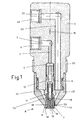
- Figure 1 shows the atomizing nozzle in diametrical section. Its structural body 1 is provided with an axial hole 2 connected to a radial hole 3 facing a threaded coaxial radial hole 4. This threaded hole is connected to a usual male-threaded end (not shown) of a low pressure water pipe.
- the axial hole 2 faces a coaxial threaded hole 5. Screwed into the hole 5 there is a threaded element 6 of length such that its end 7 extends beyond the end plane 8 of the nozzle tip 9.
- an impactor member 10 provided at its inner end with an axial hole 11. Said hole 11 constitutes the extension of the hole 12 through the tubular element 6 and the axial hole 2.
- Said axial hole 11 is intercepted by a plurality of radial holes 13 opening into an annular interspace 14 having its axis 15 coinciding with the axis of the generally cylindrical-prismatic body ( Figure 7) of the nozzle.
- the impactor member 10 has an annular flat surface 16 perpendicular to the axis 15 and bounded by sharp edges. The function of the annular flat surface 16 is to intercept the tubular fluid stream leaving the annular interspace 14. Said interception, aided by preliminary breakage of the fluid stream by a circumferential groove 17, creates further disintegration of this stream. This disintegrating action, created by direct impact of the water stream against the sharp-edged surfaces of the impactor member 10, results in centrifugal dispersion of the water.
- the water mass is struck by a very violent annular jet of compressed air peripherally to the more central origin of the water being centrifuged, to atomize it.
- Said compressed air jet arrives at very high velocity by passing through an interspace 18 formed between an outer cylindrical surface 19 of the tubular element 6 and the cylindrical walls of a hole 20.
- the result of this impact between air, water and the impactor member is disintegration of the water into microscopic droplets of just a few microns in size.
- the air blown through the interspace 18 originates from a conical collection and acceleration chamber 21 communicating with a non-central longitudinal hole 22 present in the nozzle body 1.
- Said longitudinal hole 22 connects to a radial hole 23 associated in its peripheral portion with a threaded hole 24.
- This hole is engaged by the male-threaded end (not shown) of a compressed air pipe feeding the nozzle.
- the illustrated nozzle is formed from a conical endpiece 25 screwed onto the structural body 1 after screwing the tubular element 6 into the structural body 1.
- the structural body 1 is provided externally with a male thread 26 by which it can be fixed to usual fixing means in proximity to the area on which the atomizing nozzle is to operate. As atomizing nozzles are required to operate in different spaces and on different materials, it is useful to be able to vary the shape of the cloud generated by them and also the composition of the air-water mixture.
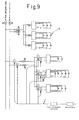
- valve means 27, 28 are connected into the air and water pipes to vary the flow cross-sections, and hence the flow rates, to set the optimum pressures and velocities of these fluids.
- the nozzles of the invention operate with a water pressure of between 0.1 and 2 bar, and an air pressure of between 1 and 5 bar.
- the physical and chemical characteristics of the water used can vary depending on the geographical location of the system incorporating the nozzles, optimum atomization could require slight modifications to the aforedefined concept.
- the nozzles of the invention could use an impactor member which differs for specific requirements.
- Figure 2 shows an impactor member 10A provided with a second annular flat surface 29 to form two interception and impact steps for the stream under disintegration.
- an impactor member with four steps is used, it comprising a further two annular flat surfaces 30 and 31 in addition to surfaces 16A, 29A identical to those described.
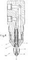
- Figure 4 a further example, shows an impactor member 10B comprising a threaded stem 32 on which a cup-shaped disintegration surface 33 is mounted and retained by a nut 34 screwed onto the stem 32.
- the threaded stem 32 is used to rotatably support a "turbine" 36 consisting of a usual toothed elastic washer of the type used to prevent slackening of nuts.
- said turbine 36 is supported by a usual nut 35, which is prevented from unscrewing either by providing it with a left-handed thread or by providing other usual friction-type retention means. Prevention of unscrewing is further aided by axially supporting the turbine 36 on a suitable washer 43 which rests on the nut 35.
- the pivot about which the turbine rotates consists of a ring nut 44 tightly screwed onto the threaded stem 32. Said turbine 36 advantageously facilitates centrifugal movement of the tubular water stream.
- the threaded stem 32 supports a plurality of washers 37, 38, 39, 40 clamped against a ledge 41 by a nut 42 in an arrangement such that their edges form overall that geometrical shape considered most advantageous.
- an impactor member 45 screwed onto one end 46 of a tubular stem 47, is provided with a disintegrating impact chamber 48 shaped conically to convey towards the nozzle body 1C the water injected into the chamber through radial holes 49. Said holes connect to a conduit 50 provided in the tubular stem 47 and opening into a usual threaded water inlet hole 51. Compressed air enters through a threaded hole 52 which opens into an annular chamber 53 to then leave freely to the outside through an annular slit 54.
- FIG. 11 shows a version of an atomizing nozzle in which the compressed air is expelled as a plurality of annular jets flowing through concentric circumferential slits 58A, 58B, 58C.
- These slits are formed by combining a plurality of funnel-shaped endpieces 57, specifically 57A, 57B, 57C in the present case, having their top edge 59a, 59B, 59C joined together by tightening a ring nut 60.
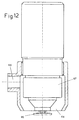
- the funnel-shaped endpieces 57 are provided with holes 61 in their conical surface, except the most outer (57A in Figure 11). This advantageously subjects the water, during centrifugal expansion after leaving the internal conduit 62 and after bouncing off a base surface 63 of an impactor member, to a plurality of atomizing air pressure changes. This results in a specific atomized water quality, suitable for certain specific types of dust. Said funnel-shaped endpieces are also interchangeable with others of different size to enable mist flow rates to be produced to match the possible different situations. With reference to Figure 12, the atomizing nozzle forms an annular air jet of relatively low pressure and large throughput opening onto the periphery of an impactor disc 65 via a large outflow port 64.
Landscapes
- Nozzles (AREA)
- Perforating, Stamping-Out Or Severing By Means Other Than Cutting (AREA)
- Disintegrating Or Milling (AREA)
- Special Spraying Apparatus (AREA)
Applications Claiming Priority (2)
| Application Number | Priority Date | Filing Date | Title |
|---|---|---|---|
| ITBG990027 | 1999-04-29 | ||
| IT1999BG000027A IT1309484B1 (it) | 1999-04-29 | 1999-04-29 | Ugello micronizzatore di acqua ad impatto, per abbattimento polveri. |
Publications (2)
| Publication Number | Publication Date |
|---|---|
| EP1048358A2 true EP1048358A2 (fr) | 2000-11-02 |
| EP1048358A3 EP1048358A3 (fr) | 2001-11-21 |
Family
ID=11336707
Family Applications (1)
| Application Number | Title | Priority Date | Filing Date |
|---|---|---|---|
| EP00107824A Withdrawn EP1048358A3 (fr) | 1999-04-29 | 2000-04-12 | Buse d'atomisation à surface d'impact pour la lutte contre les poussières |
Country Status (2)
| Country | Link |
|---|---|
| EP (1) | EP1048358A3 (fr) |
| IT (1) | IT1309484B1 (fr) |
Cited By (6)
| Publication number | Priority date | Publication date | Assignee | Title |
|---|---|---|---|---|
| FR2873587A1 (fr) * | 2004-07-27 | 2006-02-03 | Toulouse Parfum Ind Soc Par Ac | Appareil de diffusion de composes actifs dans l'atmosphere |
| WO2011004061A1 (fr) * | 2009-06-18 | 2011-01-13 | Beneq Oy | Procédé et appareil de refroidissement par jet pulvérisé |
| EP2465614A4 (fr) * | 2009-08-11 | 2013-02-13 | Sekisui Medical Co Ltd | Dispositif d'application et procédé d'application de liquide |
| WO2014092657A1 (fr) * | 2012-12-12 | 2014-06-19 | Brinox, D.O.O. | Tête de lavage à rétraction à auto-nettoyage avec entraînement pneumatique |
| CN104254622A (zh) * | 2012-01-03 | 2014-12-31 | 倍耐克有限公司 | 用于使材料回火的方法、装置和用途 |
| CN118236591A (zh) * | 2023-12-14 | 2024-06-25 | 广州君霖医疗科技有限公司 | 一种雾化器 |
Family Cites Families (7)
| Publication number | Priority date | Publication date | Assignee | Title |
|---|---|---|---|---|
| CH272044A (de) * | 1949-02-28 | 1950-11-30 | Notz Gottlieb | Farbspritzpistole. |
| GB1207609A (en) * | 1968-08-06 | 1970-10-07 | Nat Res Dev | Improvements in or relating to fluid atomisers |
| US3825188A (en) * | 1973-03-23 | 1974-07-23 | Par Wey Mfg Co | Liquid spray head |
| US4386738A (en) * | 1981-10-02 | 1983-06-07 | Combustion Engineering, Inc. | Sonic atomizing spray nozzle |
| AT378462B (de) * | 1983-10-07 | 1985-08-12 | Heid Ag Maschf | Vorrichtung zur gleichmaessigen dosierung, verteilung und aufbringung von fluessig formulierten schutzstoffen, insbesondere beizmitteln |
| JPH06226149A (ja) * | 1993-02-02 | 1994-08-16 | Matsushita Electric Ind Co Ltd | 液体微粒化装置 |
| DE19654321A1 (de) * | 1996-12-24 | 1998-06-25 | Pe Product Engineering Gmbh | Vorrichtung zur Aerosolerzeugung |
-
1999
- 1999-04-29 IT IT1999BG000027A patent/IT1309484B1/it active
-
2000
- 2000-04-12 EP EP00107824A patent/EP1048358A3/fr not_active Withdrawn
Cited By (12)
| Publication number | Priority date | Publication date | Assignee | Title |
|---|---|---|---|---|
| FR2873587A1 (fr) * | 2004-07-27 | 2006-02-03 | Toulouse Parfum Ind Soc Par Ac | Appareil de diffusion de composes actifs dans l'atmosphere |
| WO2006018511A3 (fr) * | 2004-07-27 | 2006-04-20 | Toulouse Parfum Ind | Appareil de diffusion de composes actifs dans l’atmosphere |
| WO2011004061A1 (fr) * | 2009-06-18 | 2011-01-13 | Beneq Oy | Procédé et appareil de refroidissement par jet pulvérisé |
| CN102803520A (zh) * | 2009-06-18 | 2012-11-28 | Beneq有限公司 | 用于通过雾化喷雾冷却材料的方法和设备 |
| CN102803520B (zh) * | 2009-06-18 | 2014-12-31 | Beneq有限公司 | 用于通过雾化喷雾冷却材料的方法和设备 |
| EP2465614A4 (fr) * | 2009-08-11 | 2013-02-13 | Sekisui Medical Co Ltd | Dispositif d'application et procédé d'application de liquide |
| US8893643B2 (en) | 2009-08-11 | 2014-11-25 | Sekisui Medical Co., Ltd. | Coating apparatus and liquid substance coating method |
| CN104254622A (zh) * | 2012-01-03 | 2014-12-31 | 倍耐克有限公司 | 用于使材料回火的方法、装置和用途 |
| WO2014092657A1 (fr) * | 2012-12-12 | 2014-06-19 | Brinox, D.O.O. | Tête de lavage à rétraction à auto-nettoyage avec entraînement pneumatique |
| RU2653115C2 (ru) * | 2012-12-12 | 2018-05-07 | Бринокс, Д.О.О. | Самоочищающаяся убирающаяся моечная головка с пневмоприводом |
| CN118236591A (zh) * | 2023-12-14 | 2024-06-25 | 广州君霖医疗科技有限公司 | 一种雾化器 |
| CN118236591B (zh) * | 2023-12-14 | 2025-09-02 | 广州君霖医疗科技有限公司 | 一种雾化器 |
Also Published As
| Publication number | Publication date |
|---|---|
| IT1309484B1 (it) | 2002-01-23 |
| EP1048358A3 (fr) | 2001-11-21 |
| ITBG990027A1 (it) | 2000-10-29 |
Similar Documents
| Publication | Publication Date | Title |
|---|---|---|
| US5090619A (en) | Snow gun having optimized mixing of compressed air and water flows | |
| RU2497597C2 (ru) | Способ и форсунка для распыления жидкости | |
| US4456181A (en) | Gas liquid mixing nozzle | |
| CA1276664C (fr) | Element vibratoire pour l'injection ultrasonique | |
| EP0904842A2 (fr) | Système de pulvérisation à air | |
| JPH0994494A (ja) | 内部混合気の霧化噴霧用ノズル | |
| RU2305604C2 (ru) | Гранулятор с псевдоожиженным слоем и используемый в нем распылитель | |
| KR860001616A (ko) | 삼방향 유체공급식 분무 노즐 및 그 사용방법 | |
| US3934823A (en) | Low drift spray nozzle | |
| JPH07508680A (ja) | 空気噴霧ノズル | |
| US20090230215A1 (en) | Apparatus for generating and spraying an aerosol | |
| JPH05184976A (ja) | 溝付き偏向面を有するスプレーノズル装置 | |
| US20070164459A1 (en) | Nozzle for atomising a liquid by means of a gas and method of atomising | |
| EP1048358A2 (fr) | Buse d'atomisation à surface d'impact pour la lutte contre les poussières | |
| US2674494A (en) | Shear nozzle for spraying and dusting apparatus | |
| SU1623781A1 (ru) | Пневматический распылитель жидкости - туманообразователь | |
| WO2005097345A1 (fr) | Atomiseur de liquide | |
| US4063686A (en) | Spray nozzle | |
| JPH01228564A (ja) | 噴霧距離の調節可能な液体噴霧用ノズル | |
| RU109997U1 (ru) | Распылитель жидкости | |
| RU2272677C1 (ru) | Распылительная насадка | |
| RU2001694C1 (ru) | Пневматический распылитель внутреннего смешени | |
| RU64533U1 (ru) | Дроссельная шайба-вставка | |
| RU2793352C1 (ru) | Дождеобразующее устройство дождевальной машины | |
| EP0239395A2 (fr) | Atomiseur à ultrasons |
Legal Events
| Date | Code | Title | Description |
|---|---|---|---|
| PUAI | Public reference made under article 153(3) epc to a published international application that has entered the european phase |
Free format text: ORIGINAL CODE: 0009012 |
|
| AK | Designated contracting states |
Kind code of ref document: A2 Designated state(s): AT BE CH CY DE DK ES FI FR GB GR IE IT LI LU MC NL PT SE |
|
| AX | Request for extension of the european patent |
Free format text: AL;LT;LV;MK;RO;SI |
|
| PUAL | Search report despatched |
Free format text: ORIGINAL CODE: 0009013 |
|
| AK | Designated contracting states |
Kind code of ref document: A3 Designated state(s): AT BE CH CY DE DK ES FI FR GB GR IE IT LI LU MC NL PT SE |
|
| AX | Request for extension of the european patent |
Free format text: AL;LT;LV;MK;RO;SI |
|
| AKX | Designation fees paid | ||
| REG | Reference to a national code |
Ref country code: DE Ref legal event code: 8566 |
|
| STAA | Information on the status of an ep patent application or granted ep patent |
Free format text: STATUS: THE APPLICATION IS DEEMED TO BE WITHDRAWN |
|
| 18D | Application deemed to be withdrawn |
Effective date: 20020522 |