EP1048372B1 - Dispositif de transfert - Google Patents
Dispositif de transfert Download PDFInfo
- Publication number
- EP1048372B1 EP1048372B1 EP00108433A EP00108433A EP1048372B1 EP 1048372 B1 EP1048372 B1 EP 1048372B1 EP 00108433 A EP00108433 A EP 00108433A EP 00108433 A EP00108433 A EP 00108433A EP 1048372 B1 EP1048372 B1 EP 1048372B1
- Authority
- EP
- European Patent Office
- Prior art keywords
- workpiece
- jaws
- servomotor
- clamping
- gripper
- Prior art date
- Legal status (The legal status is an assumption and is not a legal conclusion. Google has not performed a legal analysis and makes no representation as to the accuracy of the status listed.)
- Expired - Lifetime
Links
- 230000005540 biological transmission Effects 0.000 claims abstract description 9
- 230000033001 locomotion Effects 0.000 claims description 19
- 230000000694 effects Effects 0.000 claims description 2
- 238000000034 method Methods 0.000 description 3
- 230000035515 penetration Effects 0.000 description 2
- 241001295925 Gegenes Species 0.000 description 1
- 230000001154 acute effect Effects 0.000 description 1
- 230000006978 adaptation Effects 0.000 description 1
- 230000001276 controlling effect Effects 0.000 description 1
- 238000001514 detection method Methods 0.000 description 1
- 230000009931 harmful effect Effects 0.000 description 1
- 239000002655 kraft paper Substances 0.000 description 1
- 238000004519 manufacturing process Methods 0.000 description 1
- 238000003825 pressing Methods 0.000 description 1
- 230000005855 radiation Effects 0.000 description 1
- 230000001105 regulatory effect Effects 0.000 description 1
- 239000000126 substance Substances 0.000 description 1
- 230000001360 synchronised effect Effects 0.000 description 1
Images




Classifications
-
- B—PERFORMING OPERATIONS; TRANSPORTING
- B21—MECHANICAL METAL-WORKING WITHOUT ESSENTIALLY REMOVING MATERIAL; PUNCHING METAL
- B21K—MAKING FORGED OR PRESSED METAL PRODUCTS, e.g. HORSE-SHOES, RIVETS, BOLTS OR WHEELS
- B21K27/00—Handling devices, e.g. for feeding, aligning, discharging, Cutting-off means; Arrangement thereof
- B21K27/02—Feeding devices for rods, wire, or strips
- B21K27/04—Feeding devices for rods, wire, or strips allowing successive working steps
-
- B—PERFORMING OPERATIONS; TRANSPORTING
- B21—MECHANICAL METAL-WORKING WITHOUT ESSENTIALLY REMOVING MATERIAL; PUNCHING METAL
- B21D—WORKING OR PROCESSING OF SHEET METAL OR METAL TUBES, RODS OR PROFILES WITHOUT ESSENTIALLY REMOVING MATERIAL; PUNCHING METAL
- B21D43/00—Feeding, positioning or storing devices combined with, or arranged in, or specially adapted for use in connection with, apparatus for working or processing sheet metal, metal tubes or metal profiles; Associations therewith of cutting devices
- B21D43/02—Advancing work in relation to the stroke of the die or tool
- B21D43/04—Advancing work in relation to the stroke of the die or tool by means in mechanical engagement with the work
- B21D43/05—Advancing work in relation to the stroke of the die or tool by means in mechanical engagement with the work specially adapted for multi-stage presses
- B21D43/055—Devices comprising a pair of longitudinally and laterally movable parallel transfer bars
-
- B—PERFORMING OPERATIONS; TRANSPORTING
- B21—MECHANICAL METAL-WORKING WITHOUT ESSENTIALLY REMOVING MATERIAL; PUNCHING METAL
- B21D—WORKING OR PROCESSING OF SHEET METAL OR METAL TUBES, RODS OR PROFILES WITHOUT ESSENTIALLY REMOVING MATERIAL; PUNCHING METAL
- B21D43/00—Feeding, positioning or storing devices combined with, or arranged in, or specially adapted for use in connection with, apparatus for working or processing sheet metal, metal tubes or metal profiles; Associations therewith of cutting devices
- B21D43/02—Advancing work in relation to the stroke of the die or tool
- B21D43/04—Advancing work in relation to the stroke of the die or tool by means in mechanical engagement with the work
- B21D43/10—Advancing work in relation to the stroke of the die or tool by means in mechanical engagement with the work by grippers
Definitions
- the invention relates to a transport device, especially for moving workpieces, especially in a forming machine for massive forming, according to the preamble of claims 1 and 2.
- a transport device especially for moving workpieces, especially in a forming machine for massive forming, according to the preamble of claims 1 and 2.
- Such a facility is out DE-A-2 741 581.
- stations can, for example, form stages in be a pressing tool, the workpiece then from Must be transported step by step.
- each Gripper device is designed like a pair of pliers and has two pivotable towards and away from each other stored jaws. They form two-armed levers, one of which has a lever arm for clamping the workpiece and whose other lever arm is used for actuation. To do this the lever arms are connected to a rack by means of drawers, their back and forth movement into one Swiveling movement of the jaws is implemented. The drawers are arranged so that when the Close the jaws, almost at right angles to the direction of movement the rack. It follows from this a very large reduction and vice versa a very high force gain against the closing of the closing movement Jaws. To operate the jaws are used with the Rack-meshing gears that come from the main press drive are driven here.
- a transfer device a multi-stage forming press known in which on a movable Carrier a number of grippers is provided which two gripping jaws and one actuator for each Have gripping jaws in which each gripper has a long Workpiece is assigned to eject and implement and where each gripper grips the gripping jaws of the associated workpiece and the actuator is designed such that the gripping jaws for one with a guide pressure permitting ejection slip and on the other hand with one that carries the workpiece Holding pressure is applied to the workpiece, with each gripper actuator hydraulic and trained is that in a controlled manner the holding pressure is higher than that Leadership pressure is.
- the object of the invention is to improve this To create transport facility.
- the Transport device according to claim 1 has at least one, preferably several gripper devices on which one drive device each individually assigned is. This means that each gripper has its own drive Has. In principle, the gripping movement is therefore independent controllable by the gripping movement of the other grippers, adjustable and controllable. This does not allow only if necessary also a non-synchronous working of the individual gripper, but also control and control the gripping forces, possibly independent of component tolerances.
- the servomotor is preferably with a position transmitter connected, which is connected to a control device is to control the gripper device.
- the servomotor can be equipped with one device to detect the force applied by the servomotor be connected, which then also with the control device connected is.
- the facility to monitor the Clamping force can be, for example, a force sensor based on a Strain gauge, a current sensor in the servomotor Power supply line or other suitable Sensor.
- the transport device allows a fine control of the movement of the jaws or a Fine control of the jaws on the workpiece exerted force. This is especially true when the gearbox a defined power transmission characteristic without singularities, such as occur with toggle lever gears, having. This not only makes it possible to adapt the Gripping movement at any within the production tolerance irregularities lying on the workpiece, but also the control of the holding force so that damage to the Workpiece can be avoided and still hold securely of the workpiece is made possible.
- the Clamping jaws apart from their clamping position and their opening position take on a third position and function, which, for example, lies in guiding the workpiece without clamp it in place.
- a gripper device holds a workpiece for example above a die, it is possible to To reduce clamping force so that the workpiece from the Jaws slipped between them and in the die enters. This measure makes it possible to simplify the transport curve of the gripping device. For example. it can occur when inserting workpieces into the die the gripper device on the die can be dispensed with to move there.
- the drive source a servo motor is provided, the rotation of which converted into a linear movement by a spindle gear becomes.
- a roller screw is preferred used even with large transmitted forces has low friction.
- the linear motion will via a lever gear, i.e. only Transfer two pull tabs to the jaws.
- the pull tab with the lever arm of the jaw, with which she cooperates, in the clamped position Jaw encloses approximately a right angle. In this area is the power transmission from the output of the spindle gear on the jaw from the angular position of the jaws relatively independent.
- the reduction ratio is almost constant in terms of controllability the gripper device accommodates.
- the gripper device is preferably with others Gripper devices attached together on a holding rail. This is preferably designed such that it defines a closed interior.
- the drive device and the gear can be completely in the Interior. Here they are harmful Effects largely protected. This is especially true with regard to any originating from the workpiece Heat radiation in semi-hot forming processes. If necessary, can the interior enclosed by the holding rail be pressurized with compressed air to prevent penetration of disruptive substances and their penetration to the transmission, to prevent the threaded spindle and / or the servomotor.
- a transport device 1 is illustrated in FIG. 1, to transport workpieces 2 through several dies 4, 5 provided in a tool 3 are provided is.
- the holding rail 7 faces the tool 3 Page 11 one or more gripper devices 12, 14, which are set up to close the workpiece 2 seize and transport station by station.
- the gripper devices 12, 14 are identical built up. The following description of the gripper device 12 accordingly relates to the gripper device 14.
- the gripper device 12 has one provided on the front 11 of the support rail 7 support 15 on, an upper and a lower support plate 16, 17 includes.
- the carrier 15 has a passage on, in the interior enclosed by the holding rail leads. There are two between the two carrier plates 16, 17 Clamping jaws 18, 19 arranged in the clamping position extend approximately parallel to each other away from the carrier 15.
- the jaws 18, 19 protrude from the carrier 15 and are corresponding between the carrier plates 16, 17 Pins 21, 22 can be pivoted towards and away from one another stored.
- free end are the jaws 18 with receiving means provided for the workpiece 2. For example. carries the jaws 18 a prism on its side facing the workpiece 2 23, while the jaws 19 have a flat contact surface 24 having.
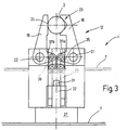
- FIGS. 2 and 3 12 associated drive device 26, to which an actuator 27 and a gear 28 belongs.
- the servomotor 27 is with its output shaft 29 with a threaded spindle 31 connected, on which a threaded bushing 32 sitting.
- This is connected to a slide 33 which of the servo motor 27 away and towards this in the direction of Axis of rotation of the threaded spindle 31, but parallel against this is displaceable.
- the slide 33 is there guided in a guide indicated only schematically.
- On the gripper device 12 facing it He carries pivotable pull tabs 35, 36 with her from the end of the slide 33 pivoted with a lever arm 37a, 37b of the respective jaw 18, 19 are connected.
- the lever arms 37a, 37b are approximately in the right angle or at an acute angle to the remaining sections extending to the workpiece 2 the jaws 18, 19 oriented. In the closed position, when the prism 23 and the flat surface 24 on the workpiece 2, the lever arms 37a, 37b close with the pull tabs 35, 36 each make a right angle. lower However, deviations are permitted.
- the transport device 1 described so far works as follows:
- the servo motor is controlled so that it, as illustrated in Figure 3, the threaded sleeve 32 and pulls the slide 33 away from the gripper device 12.
- the pull tabs 35, 36 pivot the clamping jaws 18, 19 by pulling the lever arms 37a, 37b, in Clamping position.
- the jaws 18, 19 around the 7 with respect to the holding rail, by the bolts 21, 22nd Defined fixed swivel axes swiveled. Find them Clamping jaws 18, 19 on the workpiece 2 and will the servo motor 27 is further controlled, the jaws clamp 18, 19 the workpiece 2 firmly.
- the torque of the Servo motor 27 is driven by the gear 28 by the threaded spindle 31, the slide 33, the pull tabs 35, 36 and the lever arms 37a, 37b is formed on the workpiece 2 transferred.
- the clamping force on the workpiece 2 relatively independent of its geometric shape and dimensional accuracy be regulated. This is independent of the Regulation of the gripping device 14 possible.
- the actuator can be braked in the holding position or hold by a cogging torque without rotation.
- sensors are provided which the applied, exerted or transferred forces or the position of the servo motor 27 or parts of the transmission Mark 26.
- sensors are provided which the applied, exerted or transferred forces or the position of the servo motor 27 or parts of the transmission Mark 26.
- sensors are provided which the applied, exerted or transferred forces or the position of the servo motor 27 or parts of the transmission Mark 26.
- sensors are provided which the applied, exerted or transferred forces or the position of the servo motor 27 or parts of the transmission Mark 26.
- sensors are provided which the applied, exerted or transferred forces or the position of the servo motor 27 or parts of the transmission Mark 26.
- an angle encoder on the servo motor 27 be provided.
- a path encoder can also be added the slider may be provided.
- the motor current be evaluated as a measure of the torque generated.
- torque or force sensors can be provided become.
- the servo motor 27 and the gear 26 can be complete be accommodated in the interior of the rail 7. Any sensors can also be arranged here. This activates and records the Movement of the gripper device 12 or the other control their work from the inside. This can if necessary, pressurized with compressed air, e.g. emerges from the interior at the gripper devices 12, 14 and thus the servo motors 27 and the gear 28 cools. In addition, the air escaping here prevents this Ingress of dirt.
- FIGS. 5 to 7 show a modified embodiment the transport device 1 illustrates. So far basic structural and / or functional correspondence with the embodiment described above of the transport device 1, are without renewed Explanation uses the same reference numerals. On the previous description is referenced.
- FIGS. 6 and 7 23a, 23b can be provided on the jaws 18, 19 if necessary, and how Exchangeable prisms are shown in FIGS. 6 and 7 23a, 23b can be provided. These allow an easy one Adaptation to different workpieces 2.
- One Adjustment of the gripper device 12 can usually be omitted.
- the control device not further illustrated can control the servo motor 27 so that when it is reached a desired clamping force stops and the clamping force maintains.
- a Position control or control can be provided at the different clamping and release positions through programming be specified.
- the clamping forces be set by programming what mechanical Make adjustments unnecessary.
Landscapes
- Engineering & Computer Science (AREA)
- Mechanical Engineering (AREA)
- Manipulator (AREA)
- Specific Conveyance Elements (AREA)
- Automobile Manufacture Line, Endless Track Vehicle, Trailer (AREA)
- Crystals, And After-Treatments Of Crystals (AREA)
- Details Of Garments (AREA)
Claims (2)
- Dispositif de transport (1), en particulier pour le transfert de pièces à travailler (2), en particulier dans une machine de formage, avec au moins un dispositif de préhension (12) pour saisir une pièce (2), qui présente au moins une mâchoire de serrage (18) mobile, et avec au moins un dispositif d'entraínement (26) qui est associé individuellement au dispositif de préhension (12) pour saisir et délivrer individuellement la pièce (2) dans le dispositif de préhension (12) associé, le dispositif d'entraínement (26) comprenant un servomoteur (27) ainsi qu'un réducteur (28) pour transmettre le mouvement produit par le servomoteur (27) au dispositif de préhension (12), la force de serrage exercée sur la pièce (2) par les mâchoires de serrage (18, 19) pouvant être contrôlée de manière définie par le servomoteur (27), les mâchoires de serrage (18, 19) étant chacune montées pivotantes autour d'un axe de rotation (21, 22) fixe, caractérisé par le fait qu'un bras de levier de chaque mâchoire de serrage est relié par des biellettes de traction (35, 36) à la sortie d'un mécanisme à vis sans fin (32).
- Dispositif de transport (1), en particulier pour le transfert de pièces à travailler (2), en particulier dans une machine de formage, avec au moins un dispositif de préhension (12) pour saisir une pièce (2), qui présente au moins une mâchoire de serrage (18) mobile, et avec au moins un dispositif d'entraínement (26) qui comprend un servomoteur (27) et un réducteur (28) pour transmettre le mouvement produit par le servomoteur (27) au dispositif de préhension (12), la force de serrage exercée sur la pièce (2) par les mâchoires de serrage (18, 19) pouvant être contrôlée de manière définie par le servomoteur (27), les mâchoires de serrage (18, 19) étant autour d'un axe de rotation (21, 22) fixe, caractérisé par le fait qu'un bras de levier de chaque mâchoire de serrage est relié par des biellettes de traction (35, 36) à la sortie d'un mécanisme à vis sans fin (32).
Applications Claiming Priority (2)
| Application Number | Priority Date | Filing Date | Title |
|---|---|---|---|
| DE19919434A DE19919434A1 (de) | 1999-04-29 | 1999-04-29 | Einrichtung zum Teiletransfer |
| DE19919434 | 1999-04-29 |
Publications (3)
| Publication Number | Publication Date |
|---|---|
| EP1048372A2 EP1048372A2 (fr) | 2000-11-02 |
| EP1048372A3 EP1048372A3 (fr) | 2001-08-22 |
| EP1048372B1 true EP1048372B1 (fr) | 2004-06-16 |
Family
ID=7906228
Family Applications (1)
| Application Number | Title | Priority Date | Filing Date |
|---|---|---|---|
| EP00108433A Expired - Lifetime EP1048372B1 (fr) | 1999-04-29 | 2000-04-18 | Dispositif de transfert |
Country Status (4)
| Country | Link |
|---|---|
| US (1) | US6435336B1 (fr) |
| EP (1) | EP1048372B1 (fr) |
| AT (1) | ATE269178T1 (fr) |
| DE (2) | DE19919434A1 (fr) |
Cited By (3)
| Publication number | Priority date | Publication date | Assignee | Title |
|---|---|---|---|---|
| WO2017186672A1 (fr) | 2016-04-28 | 2017-11-02 | Hatebur Umformmaschinen Ag | Dispositif de transport pour déplacer des pièces dans un dispositif d'usinage |
| WO2017186675A1 (fr) | 2016-04-28 | 2017-11-02 | Hatebur Umformmaschinen Ag | Procédé de transport pour la manutention de pièces |
| WO2017186673A1 (fr) | 2016-04-28 | 2017-11-02 | Hatebur Umformmaschinen Ag | Dispositif de transport à pinces de préhension |
Families Citing this family (30)
| Publication number | Priority date | Publication date | Assignee | Title |
|---|---|---|---|---|
| JP2003142547A (ja) * | 2001-08-24 | 2003-05-16 | Hirata Corp | ワーク搬送装置 |
| US7380654B2 (en) * | 2002-07-26 | 2008-06-03 | Abbott Laboratories | Conveyor track drive |
| ITVR20030094A1 (it) * | 2003-08-01 | 2005-02-02 | Amafa Service S R L | Trasferitore di semilavorati su presse multistazioni per il processo |
| JP4079368B2 (ja) * | 2003-08-19 | 2008-04-23 | 東洋自動機株式会社 | スパウト又はスパウト付き袋の供給装置 |
| US7438192B1 (en) | 2004-05-28 | 2008-10-21 | Owens-Brockway Glass Container Inc. | Electronic control system for container indexing and inspection apparatus |
| DE102005033767A1 (de) * | 2005-07-15 | 2007-01-18 | Müller Weingarten AG | Vorrichtung zum Halten und Manipulieren von Werkstücken beim Massivumformen |
| DE502007001577D1 (de) * | 2006-01-24 | 2009-11-05 | Hatebur Umformmaschinen Ag | Werkstücktransportvorrichtung |
| ITVE20070020A1 (it) * | 2007-04-02 | 2008-10-03 | Bifrangi S P A | Pressa orizzontale perfezionata per forgiatura. |
| CN102416425B (zh) * | 2011-09-22 | 2013-09-18 | 浙江大学 | 适用于紧固件生产的带有机械手的全自动冲床 |
| PL2777053T3 (pl) | 2011-11-11 | 2016-06-30 | Schleuniger Holding Ag | Urządzenie do skręcania |
| JP6072054B2 (ja) | 2011-11-11 | 2017-02-01 | シュロニガー ホールディング アーゲー | ケーブル受取装置(ワイヤースタッカー) |
| EP2777052B1 (fr) * | 2011-11-11 | 2016-04-13 | Schleuniger Holding AG | Dispositif de transport pour lignes |
| CH706757A1 (de) * | 2012-07-23 | 2014-01-31 | Ferag Ag | Greifer, Förderanlage und Verfahren zum Betrieb einer solchen Förderanlage. |
| CN102806562A (zh) * | 2012-09-10 | 2012-12-05 | 江南现代工业研究院 | 用于工件夹取的机械手 |
| PT2801984T (pt) | 2013-05-08 | 2019-01-23 | Schleuniger Holding Ag | Prendedor, cabeça de torção e dispositivo de torção |
| CN103639344A (zh) * | 2013-11-28 | 2014-03-19 | 苏州市宏晟锻造有限公司 | 一种用于制造饼状产品的锻造机抱钳结构 |
| CN103722441A (zh) * | 2013-12-21 | 2014-04-16 | 孙红琴 | 一种机械手臂 |
| CN106255418B (zh) | 2014-05-20 | 2020-02-07 | Gea食品策划韦尔特公司 | 棒棒糖成形单元与棒棒糖包裹单元之间的转移轮 |
| CN106064211A (zh) * | 2016-08-18 | 2016-11-02 | 沈阳翰和科技工程有限公司 | 一种热成型上、下料齿轮双动式夹钳 |
| EP3524371B1 (fr) * | 2018-02-12 | 2021-04-21 | Fagor Arrasate, S.Coop. | Système et procédé de transport de pièces à usiner dans des machines de formage |
| CN109648384B (zh) * | 2018-12-29 | 2023-11-21 | 宁波开浦智能科技有限公司 | 一种可旋转机械手爪装置 |
| DE102019206441A1 (de) * | 2019-05-06 | 2020-11-12 | Bausch + Ströbel Maschinenfabrik Ilshofen GmbH + Co. KG | Spritzenentnahme Zangenrad |
| EP3744649B1 (fr) * | 2019-05-27 | 2021-07-07 | Mespack, S.L. | Dispositif de transport pour transporter des récipients souples le long d'une ligne d'emballage |
| CN112762866B (zh) * | 2020-12-29 | 2022-07-01 | 江柴发动机徐州有限公司 | 一种发电机主轴的同轴度检测装置及其工作方法 |
| CN113369342B (zh) * | 2021-07-13 | 2025-09-12 | 山东德武防护工程有限公司 | 一种双杠双受力液压设备 |
| IT202100029057A1 (it) * | 2021-11-17 | 2023-05-17 | Gd Spa | Convogliatore per il trasporto di cartucce assemblate o semiassemblate per sigarette elettroniche |
| CN114906586A (zh) * | 2022-05-27 | 2022-08-16 | 深圳泰德半导体装备有限公司 | 夹爪组件、输送机构以及aoi检测设备 |
| CN115255171B (zh) * | 2022-07-28 | 2024-11-15 | 中山数码模汽车技术有限公司 | 一种汽车零件加工传递模及传递定位方法 |
| CN117485872A (zh) * | 2023-11-01 | 2024-02-02 | 青岛歌尔微电子研究院有限公司 | 纠偏装置及运输系统 |
| CN117300712B (zh) * | 2023-11-29 | 2024-03-19 | 杭州铁泰自动化科技有限公司 | 一种方便上下料的夹具 |
Family Cites Families (9)
| Publication number | Priority date | Publication date | Assignee | Title |
|---|---|---|---|---|
| NL165398C (nl) * | 1977-09-13 | 1981-04-15 | Nedschroef Octrooi Maats | Inrichting voor het overbrengen van te bewerken producten op een gereedschapswerktuig van het ene bewerkingsstation naar het daaropvolgende. |
| CH666644A5 (fr) * | 1985-07-04 | 1988-08-15 | Charmilles Technologies | Procede de positionnement d'une piece sur une machine-outil, dispositif pour sa mise en oeuvre et application de ce procede. |
| FR2607479B1 (fr) * | 1986-12-01 | 1991-02-15 | Remy & Cie E P | Dispositif de prehension et de retenue d'objets, tels que par exemple des recipients, sur un convoyeur, et convoyeur equipe de ce dispositif |
| FR2648072B1 (fr) * | 1989-06-08 | 1994-08-05 | Commissariat Energie Atomique | Systeme de prehension a pince commandee par un moteur asservi |
| DE4007801A1 (de) * | 1990-03-12 | 1991-09-19 | Handtmann A Punkt Automation | Einrichtung zum befuellen eines transportbehaelters |
| US5033785A (en) * | 1990-04-20 | 1991-07-23 | Woolley Jr William J | Clamp mechanism |
| IT1289906B1 (it) * | 1997-01-16 | 1998-10-19 | S B R S R L | Pinza di afferraggio di contenitori quali in particolare bottiglie |
| DE19725765C2 (de) * | 1997-06-18 | 1999-06-17 | Liebergeld Gmbh & Co | Transfervorrichtung einer Mehrstufen-Umformpresse mit Greifern zum Führen und Halten langer Werkstücke |
| US5873488A (en) * | 1997-07-21 | 1999-02-23 | Scriptpro, Llc | Vial gripper mechanism |
-
1999
- 1999-04-29 DE DE19919434A patent/DE19919434A1/de not_active Withdrawn
-
2000
- 2000-04-18 AT AT00108433T patent/ATE269178T1/de not_active IP Right Cessation
- 2000-04-18 DE DE50006788T patent/DE50006788D1/de not_active Expired - Lifetime
- 2000-04-18 EP EP00108433A patent/EP1048372B1/fr not_active Expired - Lifetime
- 2000-05-01 US US09/561,900 patent/US6435336B1/en not_active Expired - Fee Related
Cited By (5)
| Publication number | Priority date | Publication date | Assignee | Title |
|---|---|---|---|---|
| WO2017186672A1 (fr) | 2016-04-28 | 2017-11-02 | Hatebur Umformmaschinen Ag | Dispositif de transport pour déplacer des pièces dans un dispositif d'usinage |
| WO2017186675A1 (fr) | 2016-04-28 | 2017-11-02 | Hatebur Umformmaschinen Ag | Procédé de transport pour la manutention de pièces |
| WO2017186673A1 (fr) | 2016-04-28 | 2017-11-02 | Hatebur Umformmaschinen Ag | Dispositif de transport à pinces de préhension |
| US10537932B2 (en) | 2016-04-28 | 2020-01-21 | Hatebur Umformmaschinen Ag | Transport method for transferring workpieces |
| US10737313B2 (en) | 2016-04-28 | 2020-08-11 | Hatebur Umformmaschinen Ag | Transport apparatus for transferring workpieces in a processing device |
Also Published As
| Publication number | Publication date |
|---|---|
| DE19919434A1 (de) | 2000-11-02 |
| EP1048372A3 (fr) | 2001-08-22 |
| ATE269178T1 (de) | 2004-07-15 |
| EP1048372A2 (fr) | 2000-11-02 |
| US6435336B1 (en) | 2002-08-20 |
| DE50006788D1 (de) | 2004-07-22 |
Similar Documents
| Publication | Publication Date | Title |
|---|---|---|
| EP1048372A2 (fr) | Dispositif de transfert | |
| AT508923B1 (de) | Fertigungsanlage, insbesondere für das freiformbiegen | |
| DE10026829C2 (de) | Vorrichtung zum Festspannen eines Werkstücks mit unebener Oberfläche | |
| AT400415B (de) | Verfahren zur positionierung eines werkstückes und manipulatorvorrichtung für eine biegemaschine | |
| DE102016004087A1 (de) | Effektoreinheit für einen Roboter, Arbeitsvorrichtung mit einem Roboter und Verfahren zum Wechseln eines Effektors bei Robotern | |
| CH654779A5 (de) | Pneumatisch angetriebene spannvorrichtung. | |
| DE3925370B4 (de) | Materialvorschubvorrichtung für Schmiedemaschinen u. dgl. | |
| DE102018132251B4 (de) | Werkstückbefestigungswerkzeug, Werkstücktransportvorrichtung und Robotersystem | |
| DE2930006A1 (de) | Werkstueckbeschickungsvorrichtung mit beweglichkeit fuer fluchtausgleich | |
| DE2904378C2 (de) | Zangengreifarm zum Stützen und Greifen langer zylindrischer Werkstücke an Werkzeugmaschinen | |
| CH712403A1 (de) | Transportverfahren zum Umsetzen von Werkstücken zwischen mehreren aufeinanderfolgenden Stufen einer Bearbeitungseinrichtung. | |
| EP0879660A2 (fr) | Presse avec dispositif de transfert pour pièces à travailler | |
| DE3404553C2 (de) | Handhabungseinrichtung, insbesondere zum Be- und Entladen von Werkzeugmaschinen | |
| DE102005033767A1 (de) | Vorrichtung zum Halten und Manipulieren von Werkstücken beim Massivumformen | |
| EP0778094A1 (fr) | Dispositif de transfert dans presse de formages à postes multiples | |
| DE102007011188B4 (de) | Vorrichtung und ein Verfahren zum Handhaben von Schmiedeteilen | |
| CH712402A1 (de) | Transportvorrichtung mit Greifzangen zum Umsetzen von Werkstücken in einer mindestens zwei Stufen umfassenden Umformeinrichtung. | |
| CH680992A5 (fr) | ||
| EP1960160B1 (fr) | Dispositif de serrage dote de deux unites d'entrainement | |
| DD246270A5 (de) | Handhabungseinrichtung fuer montageteile | |
| DE1935451C2 (de) | Vorrichtung zum Vereinzeln und Einführen von bolzenförmigen Rohlingen an einer Bearbeitungsmaschine | |
| EP1280622A1 (fr) | Unite de transfert et son procede de commande | |
| DE69112519T2 (de) | Automatisch arbeitender Manipulator. | |
| DE3338096A1 (de) | Verfahren und vorrichtung zum ablaengen von metallenen langformguetern | |
| EP4366894B1 (fr) | Machine de traitement, table de pièce à usiner et procédé de traitement d'une pièce à usiner |
Legal Events
| Date | Code | Title | Description |
|---|---|---|---|
| PUAI | Public reference made under article 153(3) epc to a published international application that has entered the european phase |
Free format text: ORIGINAL CODE: 0009012 |
|
| AK | Designated contracting states |
Kind code of ref document: A2 Designated state(s): AT BE CH CY DE DK ES FI FR GB GR IE IT LI LU MC NL PT SE |
|
| AX | Request for extension of the european patent |
Free format text: AL;LT;LV;MK;RO;SI |
|
| PUAL | Search report despatched |
Free format text: ORIGINAL CODE: 0009013 |
|
| AK | Designated contracting states |
Kind code of ref document: A3 Designated state(s): AT BE CH CY DE DK ES FI FR GB GR IE IT LI LU MC NL PT SE |
|
| AX | Request for extension of the european patent |
Free format text: AL;LT;LV;MK;RO;SI |
|
| 17P | Request for examination filed |
Effective date: 20011113 |
|
| AKX | Designation fees paid |
Free format text: AT BE CH CY DE DK ES FI FR GB GR IE IT LI LU MC NL PT SE |
|
| 17Q | First examination report despatched |
Effective date: 20020607 |
|
| GRAP | Despatch of communication of intention to grant a patent |
Free format text: ORIGINAL CODE: EPIDOSNIGR1 |
|
| GRAS | Grant fee paid |
Free format text: ORIGINAL CODE: EPIDOSNIGR3 |
|
| GRAA | (expected) grant |
Free format text: ORIGINAL CODE: 0009210 |
|
| AK | Designated contracting states |
Kind code of ref document: B1 Designated state(s): AT BE CH CY DE DK ES FI FR GB GR IE IT LI LU MC NL PT SE |
|
| PG25 | Lapsed in a contracting state [announced via postgrant information from national office to epo] |
Ref country code: FR Free format text: LAPSE BECAUSE OF NON-PAYMENT OF DUE FEES Effective date: 20040616 Ref country code: FI Free format text: LAPSE BECAUSE OF FAILURE TO SUBMIT A TRANSLATION OF THE DESCRIPTION OR TO PAY THE FEE WITHIN THE PRESCRIBED TIME-LIMIT Effective date: 20040616 Ref country code: GB Free format text: LAPSE BECAUSE OF FAILURE TO SUBMIT A TRANSLATION OF THE DESCRIPTION OR TO PAY THE FEE WITHIN THE PRESCRIBED TIME-LIMIT Effective date: 20040616 Ref country code: NL Free format text: LAPSE BECAUSE OF FAILURE TO SUBMIT A TRANSLATION OF THE DESCRIPTION OR TO PAY THE FEE WITHIN THE PRESCRIBED TIME-LIMIT Effective date: 20040616 Ref country code: IE Free format text: LAPSE BECAUSE OF FAILURE TO SUBMIT A TRANSLATION OF THE DESCRIPTION OR TO PAY THE FEE WITHIN THE PRESCRIBED TIME-LIMIT Effective date: 20040616 Ref country code: IT Free format text: LAPSE BECAUSE OF FAILURE TO SUBMIT A TRANSLATION OF THE DESCRIPTION OR TO PAY THE FEE WITHIN THE PRESCRIBED TIME-LIMIT;WARNING: LAPSES OF ITALIAN PATENTS WITH EFFECTIVE DATE BEFORE 2007 MAY HAVE OCCURRED AT ANY TIME BEFORE 2007. THE CORRECT EFFECTIVE DATE MAY BE DIFFERENT FROM THE ONE RECORDED. Effective date: 20040616 |
|
| REG | Reference to a national code |
Ref country code: GB Ref legal event code: FG4D Free format text: NOT ENGLISH |
|
| REG | Reference to a national code |
Ref country code: CH Ref legal event code: EP |
|
| REF | Corresponds to: |
Ref document number: 50006788 Country of ref document: DE Date of ref document: 20040722 Kind code of ref document: P |
|
| REG | Reference to a national code |
Ref country code: IE Ref legal event code: FG4D Free format text: GERMAN |
|
| PG25 | Lapsed in a contracting state [announced via postgrant information from national office to epo] |
Ref country code: GR Free format text: LAPSE BECAUSE OF FAILURE TO SUBMIT A TRANSLATION OF THE DESCRIPTION OR TO PAY THE FEE WITHIN THE PRESCRIBED TIME-LIMIT Effective date: 20040916 Ref country code: DK Free format text: LAPSE BECAUSE OF FAILURE TO SUBMIT A TRANSLATION OF THE DESCRIPTION OR TO PAY THE FEE WITHIN THE PRESCRIBED TIME-LIMIT Effective date: 20040916 Ref country code: SE Free format text: LAPSE BECAUSE OF FAILURE TO SUBMIT A TRANSLATION OF THE DESCRIPTION OR TO PAY THE FEE WITHIN THE PRESCRIBED TIME-LIMIT Effective date: 20040916 |
|
| PG25 | Lapsed in a contracting state [announced via postgrant information from national office to epo] |
Ref country code: ES Free format text: LAPSE BECAUSE OF FAILURE TO SUBMIT A TRANSLATION OF THE DESCRIPTION OR TO PAY THE FEE WITHIN THE PRESCRIBED TIME-LIMIT Effective date: 20040927 |
|
| NLV1 | Nl: lapsed or annulled due to failure to fulfill the requirements of art. 29p and 29m of the patents act | ||
| GBV | Gb: ep patent (uk) treated as always having been void in accordance with gb section 77(7)/1977 [no translation filed] |
Effective date: 20040616 |
|
| REG | Reference to a national code |
Ref country code: IE Ref legal event code: FD4D |
|
| PG25 | Lapsed in a contracting state [announced via postgrant information from national office to epo] |
Ref country code: LU Free format text: LAPSE BECAUSE OF NON-PAYMENT OF DUE FEES Effective date: 20050418 Ref country code: AT Free format text: LAPSE BECAUSE OF NON-PAYMENT OF DUE FEES Effective date: 20050418 Ref country code: CY Free format text: LAPSE BECAUSE OF FAILURE TO SUBMIT A TRANSLATION OF THE DESCRIPTION OR TO PAY THE FEE WITHIN THE PRESCRIBED TIME-LIMIT Effective date: 20050418 |
|
| PLBE | No opposition filed within time limit |
Free format text: ORIGINAL CODE: 0009261 |
|
| STAA | Information on the status of an ep patent application or granted ep patent |
Free format text: STATUS: NO OPPOSITION FILED WITHIN TIME LIMIT |
|
| PG25 | Lapsed in a contracting state [announced via postgrant information from national office to epo] |
Ref country code: CH Free format text: LAPSE BECAUSE OF NON-PAYMENT OF DUE FEES Effective date: 20050430 Ref country code: LI Free format text: LAPSE BECAUSE OF NON-PAYMENT OF DUE FEES Effective date: 20050430 Ref country code: BE Free format text: LAPSE BECAUSE OF NON-PAYMENT OF DUE FEES Effective date: 20050430 Ref country code: MC Free format text: LAPSE BECAUSE OF NON-PAYMENT OF DUE FEES Effective date: 20050430 |
|
| 26N | No opposition filed |
Effective date: 20050317 |
|
| EN | Fr: translation not filed | ||
| BERE | Be: lapsed |
Owner name: *SCHULER PRESSEN G.M.B.H. & CO. K.G. Effective date: 20050430 |
|
| REG | Reference to a national code |
Ref country code: CH Ref legal event code: PL |
|
| BERE | Be: lapsed |
Owner name: *SCHULER PRESSEN G.M.B.H. & CO. K.G. Effective date: 20050430 |
|
| PG25 | Lapsed in a contracting state [announced via postgrant information from national office to epo] |
Ref country code: PT Free format text: LAPSE BECAUSE OF NON-PAYMENT OF DUE FEES Effective date: 20041116 |
|
| PGFP | Annual fee paid to national office [announced via postgrant information from national office to epo] |
Ref country code: DE Payment date: 20110408 Year of fee payment: 12 |
|
| REG | Reference to a national code |
Ref country code: DE Ref legal event code: R119 Ref document number: 50006788 Country of ref document: DE Effective date: 20121101 |
|
| PG25 | Lapsed in a contracting state [announced via postgrant information from national office to epo] |
Ref country code: DE Free format text: LAPSE BECAUSE OF NON-PAYMENT OF DUE FEES Effective date: 20121101 |