EP1048398A2 - Werkstücktransporteinrichtung mit oben angeordneter Antriebvorrichtung - Google Patents
Werkstücktransporteinrichtung mit oben angeordneter Antriebvorrichtung Download PDFInfo
- Publication number
- EP1048398A2 EP1048398A2 EP00108233A EP00108233A EP1048398A2 EP 1048398 A2 EP1048398 A2 EP 1048398A2 EP 00108233 A EP00108233 A EP 00108233A EP 00108233 A EP00108233 A EP 00108233A EP 1048398 A2 EP1048398 A2 EP 1048398A2
- Authority
- EP
- European Patent Office
- Prior art keywords
- shuttle
- lift
- workpiece
- workpieces
- workstations
- Prior art date
- Legal status (The legal status is an assumption and is not a legal conclusion. Google has not performed a legal analysis and makes no representation as to the accuracy of the status listed.)
- Withdrawn
Links
- 230000007246 mechanism Effects 0.000 claims abstract description 71
- 230000008901 benefit Effects 0.000 description 4
- 238000004519 manufacturing process Methods 0.000 description 3
- 230000002441 reversible effect Effects 0.000 description 2
- 230000000712 assembly Effects 0.000 description 1
- 238000000429 assembly Methods 0.000 description 1
- 239000000356 contaminant Substances 0.000 description 1
- 238000011109 contamination Methods 0.000 description 1
- 239000002826 coolant Substances 0.000 description 1
- 238000003754 machining Methods 0.000 description 1
- 238000012423 maintenance Methods 0.000 description 1
Images


Classifications
-
- B—PERFORMING OPERATIONS; TRANSPORTING
- B23—MACHINE TOOLS; METAL-WORKING NOT OTHERWISE PROVIDED FOR
- B23Q—DETAILS, COMPONENTS, OR ACCESSORIES FOR MACHINE TOOLS, e.g. ARRANGEMENTS FOR COPYING OR CONTROLLING; MACHINE TOOLS IN GENERAL CHARACTERISED BY THE CONSTRUCTION OF PARTICULAR DETAILS OR COMPONENTS; COMBINATIONS OR ASSOCIATIONS OF METAL-WORKING MACHINES, NOT DIRECTED TO A PARTICULAR RESULT
- B23Q7/00—Arrangements for handling work specially combined with or arranged in, or specially adapted for use in connection with, machine tools, e.g. for conveying, loading, positioning, discharging, sorting
- B23Q7/005—Lifting devices
-
- B—PERFORMING OPERATIONS; TRANSPORTING
- B23—MACHINE TOOLS; METAL-WORKING NOT OTHERWISE PROVIDED FOR
- B23Q—DETAILS, COMPONENTS, OR ACCESSORIES FOR MACHINE TOOLS, e.g. ARRANGEMENTS FOR COPYING OR CONTROLLING; MACHINE TOOLS IN GENERAL CHARACTERISED BY THE CONSTRUCTION OF PARTICULAR DETAILS OR COMPONENTS; COMBINATIONS OR ASSOCIATIONS OF METAL-WORKING MACHINES, NOT DIRECTED TO A PARTICULAR RESULT
- B23Q7/00—Arrangements for handling work specially combined with or arranged in, or specially adapted for use in connection with, machine tools, e.g. for conveying, loading, positioning, discharging, sorting
- B23Q7/003—Cyclically moving conveyors
-
- B—PERFORMING OPERATIONS; TRANSPORTING
- B23—MACHINE TOOLS; METAL-WORKING NOT OTHERWISE PROVIDED FOR
- B23Q—DETAILS, COMPONENTS, OR ACCESSORIES FOR MACHINE TOOLS, e.g. ARRANGEMENTS FOR COPYING OR CONTROLLING; MACHINE TOOLS IN GENERAL CHARACTERISED BY THE CONSTRUCTION OF PARTICULAR DETAILS OR COMPONENTS; COMBINATIONS OR ASSOCIATIONS OF METAL-WORKING MACHINES, NOT DIRECTED TO A PARTICULAR RESULT
- B23Q7/00—Arrangements for handling work specially combined with or arranged in, or specially adapted for use in connection with, machine tools, e.g. for conveying, loading, positioning, discharging, sorting
- B23Q7/14—Arrangements for handling work specially combined with or arranged in, or specially adapted for use in connection with, machine tools, e.g. for conveying, loading, positioning, discharging, sorting co-ordinated in production lines
- B23Q7/1426—Arrangements for handling work specially combined with or arranged in, or specially adapted for use in connection with, machine tools, e.g. for conveying, loading, positioning, discharging, sorting co-ordinated in production lines with work holders not rigidly fixed to the transport devices
- B23Q7/1478—Arrangements for handling work specially combined with or arranged in, or specially adapted for use in connection with, machine tools, e.g. for conveying, loading, positioning, discharging, sorting co-ordinated in production lines with work holders not rigidly fixed to the transport devices using a conveyor comprising cyclically-moving means
- B23Q7/1484—Arrangements for handling work specially combined with or arranged in, or specially adapted for use in connection with, machine tools, e.g. for conveying, loading, positioning, discharging, sorting co-ordinated in production lines with work holders not rigidly fixed to the transport devices using a conveyor comprising cyclically-moving means with carrier means
-
- B—PERFORMING OPERATIONS; TRANSPORTING
- B65—CONVEYING; PACKING; STORING; HANDLING THIN OR FILAMENTARY MATERIAL
- B65G—TRANSPORT OR STORAGE DEVICES, e.g. CONVEYORS FOR LOADING OR TIPPING, SHOP CONVEYOR SYSTEMS OR PNEUMATIC TUBE CONVEYORS
- B65G25/00—Conveyors comprising a cyclically-moving, e.g. reciprocating, carrier or impeller which is disengaged from the load during the return part of its movement
- B65G25/02—Conveyors comprising a cyclically-moving, e.g. reciprocating, carrier or impeller which is disengaged from the load during the return part of its movement the carrier or impeller having different forward and return paths of movement, e.g. walking beam conveyors
Definitions
- This invention relates generally to multiple station workpiece transfer systems and more particularly to a transfer mechanism for moving workpieces from one station to another.
- a shuffle underlies the workpieces and is raised and lowered generally vertically by elevators or lift mechanisms underlying the shuttle.
- the elevators or lift mechanisms are actuated by a drive mechanism to raise the shuttle and hence lift the workpieces from their current workstations.
- the shuttle is advanced to transfer each workpiece to a successive workstation and then lowered to deposit each workpiece in its successive workstation and subsequently the shuttle is retracted to its starting position.
- the shuttle With the elevators or lift mechanisms underlying the shuttle, the shuttle has a beginning or lowest height which is raised from the floor. To ensure that the shuttle can clear and be moved below the workpieces when received in their workstations, the workstations must have a sufficient height above the floor and above the shuttle in its lowest position. Further, to ensure that the workpieces clear their workstations when lifted by the shuttle, a relatively long vertical stoke of the shuttle is required. Each of these factors results in undesirably excessive vertical height above the floor of the workpieces when deposited on their workstations, and instability of the shuttle and workpieces when raised. Moreover, the elevators or lift mechanisms and any drive mechanisms underlying the shuttle are highly susceptible to becoming contaminated and malfunctioning due to dirt, chips and the like falling off the workpieces and fouling the mechanism.
- a typical overhead lift and carry device has its lifting mechanism and shuffle disposed above the workstations and workpieces thereon.
- a plurality of clamping or gripping devices are carried by the shuffle and are separately actuated to grip each workpiece from above the workpiece to lift it off of a workstation so that it may be carried to a successive workstation.
- the overhead lift and carry device solves some of the problems of the lift and carry devices wherein the lifting mechanisms and shuttle are disposed below the workpiece but has an undesirably long cycle time, increased complexity due to the addition of the clamping devices and may be less safe because the parts are supported and carried from above and thus may be dropped should a clamping device fail. Further, repair hoists or the like cannot be readily moved above the workpieces because they will interfere with the overhead shuttle and clamping devices.
- the shuttle To complete one cycle of a typical overhead lift and carry device, the shuttle must be lowered to dispose the clamps adjacent to their respective workpieces on the workstations. The clamps must then be closed on each workpiece to grip it and the shuttle must be raised vertically to remove the workpieces from the workstations. Thereafter, the shuttle is advanced to dispose the workpieces above successive workstations and then lowered into these successive workstations. The clamps must then be released or opened to deposit the workpieces in the workstations and the shuttle raised and thereafter returned to its original position to begin another cycle. Notably, this eight step cycle takes a considerable amount of time and thus, lowers the rate of production of the workpieces and thereby increases the cost to manufacture the parts. Further, the increased complexity of the overhead lift and carry device along with the increased number of moving parts of the device decrease its efficiency and reliability in use.
- An improved workpiece transfer apparatus with a shuttle underlying workpieces received in workstations which is actuated by a lifting mechanism disposed above the workpieces.
- the shuttle has a support rail and an indexing rail operably connected to a drive for movement relative to the support rail.
- To transfer workpieces from their current workstations to subsequent workstations, the shuttle is raised by the overhead lifting mechanism to engage the workpieces from underneath and raise the workpieces from their current workstations.
- the indexing rail is advanced to position the workpieces over subsequent workstations and the shuttle is lowered to deposit the workpieces in these subsequent workstations. Subsequently, the indexing rail is retracted to its starting position so that the apparatus is ready for the next transfer cycle.
- this apparatus has all of the advantages of a conventional overhead lift and carry device without its notable disadvantages. More specifically, the number of moving parts is reduced, no clamps are necessary to lift a workpiece from above, the workpiece is supported from underneath and the apparatus has a significantly shorter cycle time compared to a conventional overhead lift and carry device. Further, because the lift mechanism and any drive mechanism is disposed above the workpieces, the shuttle may be disposed closely adjacent to the floor in its lowered position to thereby enable the height of the workstations to be lowered to a more suitable working height.
- the lift mechanism may provide substantially straight, vertical movement of a support rail of the shuttle and may utilize a Scott Russell linkage or other linear motion lifting mechanism or substantially any other lifting mechanism with the support rail restrained to move only in a singe plane such as by a linear slide bearing and guide rail device.
- Objects, features and advantages of this invention include providing a workpiece transfer apparatus which permits workstations and workpieces therein to be disposed at a convenient working height, enables a long lifting stroke for vertical travel, has a relatively short and uncomplicated working cycle, removes the lifting mechanism from contamination by dirt and debris dropping from the workpieces, supports the workpieces from underneath to eliminate the risk of the workpieces being dropped, increases the number of workstations which may be disposed in a given floor space, is rugged, durable, reliable, relatively service and maintenance free, and of relatively simple design and economical manufacture and assembly and in service has a long useful life.
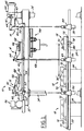
- FIGS. 1 - 5 illustrate a workpiece transfer apparatus 10 having a shuttle 12 actuated by lifting mechanisms 14 disposed above the shuttle 12.
- the shuttle 12 is disposed beneath various workpieces 16 each received in a separate workstation 18.
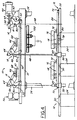
- the shuttle 12 is raised by the lifting mechanisms 14 to lift the workpieces 16 off of their workstations 18 (FIG. 3), and indexing rails 20 of the shuttle 12 are advanced relative to support rails 22 of the shuttle 12 to dispose the workpieces 16 over their subsequent workstations 18 (FIG. 4).
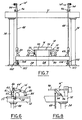
- the shuffle 12 is then lowered to place the workpieces 16 in the subsequent workstations 18 (FIG. 5) and the indexing rails 20 are retracted to their starting position so that the apparatus 10 is ready for the next transfer cycle.
- Each workstation 18 has a base 24 received on a floor 28 and locator pins 30 extending therefrom which are received through holes in the workpiece 16 to accurately align and locate the workpiece 16 in the workstation 18.
- the workpieces 18 must be raised and lowered generally vertically relative to the workstations 18 by the lift mechanisms 14.
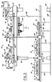
- the lift mechanisms 14 may be attached to a ceiling or supported on a box frame with transverse stringers 31 fixed to laterally spaced apart beams 32 connected to uprights 34 extending from the floor 28. As shown in FIG. 2, parallel sets of lift mechanisms 14 are provided to carry and move opposed sides of the shuttle 12.
- Each lifting mechanism 14 preferably has a bell crank 40 mounted on a pivot 41 fixed to a support plate 43 connected to the beam 32.
- the bell crank has a first arm 42 pivotally connected to a lifting link 44 which is pivotally connected at one end 46 to one end of a link or rod 48 which at its other is pivotally connected to a plate 49 attached to a cross rail 50 extending underneath each support rail 22 of the shuttle 12.
- a second arm 52 of each bell crank 40 is pivotally connected to a drag link 54 which is operably connected to an actuating rod or ball screw 55 of a drive mechanism 56 which actuates the lifting mechanisms 14. So that all of the lifting mechanisms 14 may be actuated by a single drive 56, the two bell cranks 40 of each set are connected together to rotate in unison by a torque tube 57 (FIG. 2) concentric with their pivots 41 and fixed at its ends to the two bell cranks. Actuating each lifting mechanism 14 with a single drive 56 ensures that the lifting mechanisms 14 are driven in unison to provide a stable and controlled movement of the shuttle 12.
- the lift drive 56 may be of substantially any type to advance and retract the drag link 54, such as a reversible electrical motor, hydraulic cylinder or pneumatic cylinder. If desired, the torque tubes 57 may be eliminated, and two separate drives 56 and drag links 54 provided, one on each side, to actuate the lift mechanisms 14. In any arrangement, both sets of link mechanisms 14 are driven in unison to provide an uniform, level and stable movement of the shuttle 12. To improve the stability of the apparatus 10, a counterbalance 60 is connected to the lift mechanisms 14 opposite the lift drive(s) 56.
- the counterbalance 60 is preferably a pneumatic cylinder 62 mounted by pivots 61 of a support 63 on the beam 32 with an actuating rod 64 pivotally connected to a third arm 65 of the end bell crank 40 of the adjacent lift mechanism 14 to cushion and counterbalance movement of the shuttle 12 and the workpieces.
- a second end 70 of the lifting link 44 is fixed to a linear slide 66 with bearings received on a guide track 68 carried by support plate 43.
- the slide 66 and guide track 68 cause the second end 70 of the lifting link 44 to move along a straight line path perpendicular to the line of the vertical motion of the first end 46 of the lifting link 44 and intersecting the axis of the fixed pivot 41 of the bell crank 40.
- the lifting links 44 provide an essentially straight line vertical motion of the rods 48 to raise and lower the shuttle 12 relative to the workpieces 16.
- lift mechanisms 14' may utilize Scott Russell linkages to provide linear, vertical movement for the shuttle 12.
- These lift mechanisms 14' have a short link 82 which at one end is pivotally connected to the second end 70 of lift link 44 and at the other end pivotally connected to a support plate 84 fixed to the beam 32.
- a linkage provides an essentially straight line or linear motion of the pivotal connection to rods 48.
- the shuttle 12 underlies the workpieces 16 in the workstations 18 and has a pair of laterally spaced apart support rails 22 connected to the lifting links 44 through the links or rods 48 and fixed to cross rails 50, and a pair of indexing rails 20 mounted for reciprocation on the support rails 22.
- the shuttle 12 When the shuttle 12 is raised, the workpieces 16 are received on locator and support fixtures 72 fixed to the indexing rails 20.
- Each indexing rail 20 has rollers 73 attached thereto and received in a guide track 74 fixed to its associated support rail 22 to guide the linear reciprocation of the indexing rail 20 relative to the support rail 22.
- An indexing drive 76 is carried by the shuttle 12 and operably connected to the indexing rails 20 to reciprocate the indexing rails 20 relative to the support rails 22.
- the indexing drive 76 preferably comprises a reversible electric motor (not shown) which rotates in unison a pair of drive gears 78 each meshed with a separate rack 80 fixed to each indexing rail 20.
- substantially any other type of drive may be used which is capable of reciprocating the indexing rails 20 relative to the support rails 22.
- the shuttle cross rails 50 are attached at each end to a linear slide 90 constrained for essentially vertical motion in a guide track 92 to limit the movement of the shuttle 12 to only vertical motion relative to the workstations 18.
- a linear slide 90 constrained for essentially vertical motion in a guide track 92 to limit the movement of the shuttle 12 to only vertical motion relative to the workstations 18.
- other assemblies may be used to control the movement of the shuttle 12 relative to the workstations 18.
- the lateral movement of the shuttle 12 may be eliminated by providing a follower 102 with a bushing 103 slidably received on a guide pin 104 fixed to the floor 28 at one end.
- lifting mechanisms 14'' of substantially any type may be used such as a single arm 94 pivoted at one end 96 such that its free end swings on an arc. Desirably, each lifting mechanism 14'' is still interconnected by a drag link 98 to synchronize the lifting mechanisms 14''.
- the lifting and lowering of the shuttle 12 can be essentially vertical relative to the workpieces 16 if desired. Notably, if this essentially vertical movement of the shuttle 12 is not necessary, then greater freedom is provided for the apparatus 10, its lifting mechanisms 14 and its shuttle 12.
- machining, assembly or other work may be performed on the various workpieces 16.
- the indexing rails 20 are diposed in their retracted position as shown in FIG. 1.
- the lift drive 56 is actuated to displace the drag link 54 and cause rotation of the bell cranks 40 generally counterclockwise about their pivots 41 as viewed in FIG. 1.
- This counterclockwise rotation of the bell cranks 40 causes an associated upward movement in unison of the lifting links 44 which are connected to the cross rails 50 to raise the shuttle 12 relative to the workstations 18 and to lift off and remove the workpieces 16 from the workstations 18 (FIG. 3).
- the indexing drive 76 is actuated to advance the indexing rails 20 relative to the support rails 22 to thereby dispose the workpieces 16 above their respective subsequent workstations 18 (FIG. 4).
- the lift drive 56 is reversed to cause a generally clockwise rotation of the bell cranks 40 as viewed in FIG. 1.
- the lifting mechanisms 14, 14', 14'' are disposed above the shuttle 12 which is disposed beneath the workpieces 16. Because there are no clamping devices and the shuttle 12 is not disposed above the workstations as in a conventional overhead lift and carry device, a repair hoist 100 may be used above the workpieces 16. Desirably, with the lift drive 56 and lifting mechanisms 14, 14', 14'' out of the way of the workstations 18, fixtures and/or tools therein can be interchanged, or replaced when the shuttle 12 is raised and the workpieces 16 are removed from the workstations. This greatly increases the flexibility of the apparatus 10 which may be used with different workpieces 16 by simply changing the fixtures, tooling, locators and/or workstations.
- the shuttle 12 engages the workpieces 16 from underneath to reduce the complexity of the work cycle and to increase the safety in use of the apparatus 10. Still further, with the relatively thin links 48 extending between workstations 18, the workstations 18 can be closely grouped together to increase the number of workstations 18 disposed in a given floor space.
Landscapes
- Engineering & Computer Science (AREA)
- Mechanical Engineering (AREA)
- Automobile Manufacture Line, Endless Track Vehicle, Trailer (AREA)
- Automatic Assembly (AREA)
- Intermediate Stations On Conveyors (AREA)
Applications Claiming Priority (4)
| Application Number | Priority Date | Filing Date | Title |
|---|---|---|---|
| US384612 | 1989-07-25 | ||
| US13077699P | 1999-04-23 | 1999-04-23 | |
| US130776P | 1999-04-23 | ||
| US09/384,612 US6298979B1 (en) | 1999-04-23 | 1999-08-27 | Workpiece transfer apparatus with overhead actuator |
Publications (2)
| Publication Number | Publication Date |
|---|---|
| EP1048398A2 true EP1048398A2 (de) | 2000-11-02 |
| EP1048398A3 EP1048398A3 (de) | 2001-12-05 |
Family
ID=26828801
Family Applications (1)
| Application Number | Title | Priority Date | Filing Date |
|---|---|---|---|
| EP00108233A Withdrawn EP1048398A3 (de) | 1999-04-23 | 2000-04-14 | Werkstücktransporteinrichtung mit oben angeordneter Antriebvorrichtung |
Country Status (4)
| Country | Link |
|---|---|
| US (1) | US6298979B1 (de) |
| EP (1) | EP1048398A3 (de) |
| CA (1) | CA2305937A1 (de) |
| MX (1) | MXPA00003814A (de) |
Cited By (2)
| Publication number | Priority date | Publication date | Assignee | Title |
|---|---|---|---|---|
| CN105712039A (zh) * | 2014-12-22 | 2016-06-29 | 哈耶工程与发展公司 | 一种托盘传送系统及传送方法 |
| ITMI20150577A1 (it) * | 2015-04-22 | 2016-10-22 | Elti Srl | Apparecchiatura per la movimentazione controllata, lungo una direzione di movimentazione, di manufatti in impianti di tipo continuo, particolarmente per forni di riscaldo o trattamento termico di manufatti in metallo. |
Families Citing this family (6)
| Publication number | Priority date | Publication date | Assignee | Title |
|---|---|---|---|---|
| FR2906265B1 (fr) * | 2006-09-22 | 2008-12-19 | Frederic Vacheron | Installation de traitement de surface de pieces par immerssion dans un liquide de traitement. |
| JP5083278B2 (ja) * | 2009-06-15 | 2012-11-28 | 村田機械株式会社 | 装置前自動倉庫 |
| CN103132103B (zh) * | 2011-12-02 | 2016-12-21 | 洛阳宇航重工科技股份有限公司 | 一种用于清除双阳极组上氧化铝结壳块系统的推进装置 |
| JP5855962B2 (ja) * | 2012-02-06 | 2016-02-09 | 徳田工業株式会社 | 加工システム |
| CN111792304A (zh) * | 2020-07-14 | 2020-10-20 | 惠州英特智能设备有限公司 | 直线型滑块升降循环线 |
| CN115488598B (zh) * | 2022-08-08 | 2026-02-17 | 中山市三民金属处理有限公司 | 治具拆卸设备 |
Family Cites Families (13)
| Publication number | Priority date | Publication date | Assignee | Title |
|---|---|---|---|---|
| US2856079A (en) * | 1958-10-14 | Article handler | ||
| US2033848A (en) * | 1934-07-17 | 1936-03-10 | Fruit Packers Supply And Equip | Fruit and vegetable washing machine |
| US2088284A (en) * | 1935-11-01 | 1937-07-27 | Mij Exploitatie Octrooien Nv | Device for conveying articles in continuous furnaces |
| US2930333A (en) * | 1955-10-21 | 1960-03-29 | Konink Verkade Fabricken N V | Oven for baking, heating or keeping bakers' wares at a constant temperature |
| US3016004A (en) * | 1960-01-26 | 1962-01-09 | Hygrade Food Products Corp | Meat treating |
| US4377986A (en) * | 1980-06-20 | 1983-03-29 | Juve Robert J | Hoist plating line |
| US4865180A (en) * | 1985-08-07 | 1989-09-12 | Lamb Technicon Corp. | Workpiece transfer system |
| USRE32804E (en) * | 1985-08-09 | 1988-12-20 | Lamb Technicon Corp. | Workpiece transfer |
| US4669607A (en) * | 1985-08-09 | 1987-06-02 | Lamb Technicon Corp. | Workpiece transfer |
| US4781285A (en) * | 1987-09-21 | 1988-11-01 | Progressive Tool & Industries Company | Soft touch drive for article handling apparatus |
| US5127787A (en) * | 1990-05-24 | 1992-07-07 | Brothers Industries, Inc. | Lift and carry mechanism and method |
| DE4490350C2 (de) * | 1993-01-21 | 1999-10-28 | Komatsu Mfg Co Ltd | Transferförderer |
| JP3285057B2 (ja) * | 1993-09-20 | 2002-05-27 | 豊田工機株式会社 | 自動搬送装置 |
-
1999
- 1999-08-27 US US09/384,612 patent/US6298979B1/en not_active Expired - Fee Related
-
2000
- 2000-04-14 EP EP00108233A patent/EP1048398A3/de not_active Withdrawn
- 2000-04-18 CA CA002305937A patent/CA2305937A1/en not_active Abandoned
- 2000-04-18 MX MXPA00003814A patent/MXPA00003814A/es unknown
Cited By (2)
| Publication number | Priority date | Publication date | Assignee | Title |
|---|---|---|---|---|
| CN105712039A (zh) * | 2014-12-22 | 2016-06-29 | 哈耶工程与发展公司 | 一种托盘传送系统及传送方法 |
| ITMI20150577A1 (it) * | 2015-04-22 | 2016-10-22 | Elti Srl | Apparecchiatura per la movimentazione controllata, lungo una direzione di movimentazione, di manufatti in impianti di tipo continuo, particolarmente per forni di riscaldo o trattamento termico di manufatti in metallo. |
Also Published As
| Publication number | Publication date |
|---|---|
| US6298979B1 (en) | 2001-10-09 |
| CA2305937A1 (en) | 2000-10-23 |
| EP1048398A3 (de) | 2001-12-05 |
| MXPA00003814A (es) | 2002-03-08 |
Similar Documents
| Publication | Publication Date | Title |
|---|---|---|
| CA1231109A (en) | Workpiece transfer device | |
| US4669607A (en) | Workpiece transfer | |
| CA1273314A (en) | Workpiece transfer system | |
| US6298979B1 (en) | Workpiece transfer apparatus with overhead actuator | |
| CN112059521A (zh) | 用于轻型钢结构自动焊接生产流水线的变位系统 | |
| CN108818513B (zh) | 一种回转式上片机械手 | |
| CN114772264A (zh) | 一种带取放机械手的保温杯加工液压拉伸整形设备 | |
| USRE32804E (en) | Workpiece transfer | |
| US4973443A (en) | System for removing and installing a control rod drive | |
| KR100594045B1 (ko) | 이송 프레스의 작업물 반송 구동장치 및 방법 | |
| US5878641A (en) | Cutting apparatus | |
| CN217413154U (zh) | 一种机床 | |
| CN120588198A (zh) | 一种龙门式多工位机械手动作控制机构 | |
| CN110000482B (zh) | 位置可交换的激光切割机用双工作台结构 | |
| CN113070719B (zh) | 一种全自动送料工件加工装置 | |
| JP2708918B2 (ja) | 一連の加工ステーションを通して加工物を移送するためのシステム | |
| CN117352449A (zh) | 一种igbt模块外框自动组装装置 | |
| US5019325A (en) | Method for removing and installing a control rod drive | |
| CN114798945A (zh) | 一种带机械手的液压拉伸设备 | |
| CN212580947U (zh) | 一种轴承抓取装置 | |
| CN213033461U (zh) | 折弯件及直形件的送进设备 | |
| CN211469966U (zh) | 一种具有升降功能的取出机 | |
| CN107673071A (zh) | 一种链轮传动伺服平移抓取机构 | |
| GB1489627A (en) | Rake type cooling bed for round and polygonal sections | |
| CN207712953U (zh) | 一种链轮传动伺服平移抓取机构 |
Legal Events
| Date | Code | Title | Description |
|---|---|---|---|
| PUAI | Public reference made under article 153(3) epc to a published international application that has entered the european phase |
Free format text: ORIGINAL CODE: 0009012 |
|
| AK | Designated contracting states |
Kind code of ref document: A2 Designated state(s): DE ES FR GB SE Kind code of ref document: A2 Designated state(s): AT BE CH CY DE DK ES FI FR GB GR IE IT LI LU MC NL PT SE |
|
| AX | Request for extension of the european patent |
Free format text: AL;LT;LV;MK;RO;SI |
|
| PUAL | Search report despatched |
Free format text: ORIGINAL CODE: 0009013 |
|
| AK | Designated contracting states |
Kind code of ref document: A3 Designated state(s): AT BE CH CY DE DK ES FI FR GB GR IE IT LI LU MC NL PT SE |
|
| AX | Request for extension of the european patent |
Free format text: AL;LT;LV;MK;RO;SI |
|
| RIC1 | Information provided on ipc code assigned before grant |
Free format text: 7B 23Q 7/14 A, 7B 65G 25/02 B |
|
| 17P | Request for examination filed |
Effective date: 20020314 |
|
| AKX | Designation fees paid |
Free format text: DE ES FR GB SE |
|
| GRAP | Despatch of communication of intention to grant a patent |
Free format text: ORIGINAL CODE: EPIDOSNIGR1 |
|
| STAA | Information on the status of an ep patent application or granted ep patent |
Free format text: STATUS: THE APPLICATION IS DEEMED TO BE WITHDRAWN |
|
| 18D | Application deemed to be withdrawn |
Effective date: 20040109 |