EP1048402A2 - Ponceuse à bande - Google Patents
Ponceuse à bande Download PDFInfo
- Publication number
- EP1048402A2 EP1048402A2 EP00303099A EP00303099A EP1048402A2 EP 1048402 A2 EP1048402 A2 EP 1048402A2 EP 00303099 A EP00303099 A EP 00303099A EP 00303099 A EP00303099 A EP 00303099A EP 1048402 A2 EP1048402 A2 EP 1048402A2
- Authority
- EP
- European Patent Office
- Prior art keywords
- roll
- belt
- extension
- main
- main roll
- Prior art date
- Legal status (The legal status is an assumption and is not a legal conclusion. Google has not performed a legal analysis and makes no representation as to the accuracy of the status listed.)
- Withdrawn
Links
- 239000000463 material Substances 0.000 claims description 5
- 239000004033 plastic Substances 0.000 claims description 4
- 229920003023 plastic Polymers 0.000 claims description 4
- 238000009408 flooring Methods 0.000 description 5
- 239000003082 abrasive agent Substances 0.000 description 4
- 239000000428 dust Substances 0.000 description 4
- 239000011121 hardwood Substances 0.000 description 4
- 230000004048 modification Effects 0.000 description 2
- 238000012986 modification Methods 0.000 description 2
- 239000002023 wood Substances 0.000 description 2
- 230000000694 effects Effects 0.000 description 1
- 230000001771 impaired effect Effects 0.000 description 1
- 230000014759 maintenance of location Effects 0.000 description 1
- 238000000034 method Methods 0.000 description 1
- 239000004576 sand Substances 0.000 description 1
- 229920001169 thermoplastic Polymers 0.000 description 1
- 239000004416 thermosoftening plastic Substances 0.000 description 1
Images


Classifications
-
- B—PERFORMING OPERATIONS; TRANSPORTING
- B24—GRINDING; POLISHING
- B24B—MACHINES, DEVICES, OR PROCESSES FOR GRINDING OR POLISHING; DRESSING OR CONDITIONING OF ABRADING SURFACES; FEEDING OF GRINDING, POLISHING, OR LAPPING AGENTS
- B24B7/00—Machines or devices designed for grinding plane surfaces on work, including polishing plane glass surfaces; Accessories therefor
- B24B7/10—Single-purpose machines or devices
- B24B7/18—Single-purpose machines or devices for grinding floorings, walls, ceilings or the like
- B24B7/188—Single-purpose machines or devices for grinding floorings, walls, ceilings or the like with cylinder- or belt-type tools
-
- B—PERFORMING OPERATIONS; TRANSPORTING
- B24—GRINDING; POLISHING
- B24B—MACHINES, DEVICES, OR PROCESSES FOR GRINDING OR POLISHING; DRESSING OR CONDITIONING OF ABRADING SURFACES; FEEDING OF GRINDING, POLISHING, OR LAPPING AGENTS
- B24B21/00—Machines or devices using grinding or polishing belts; Accessories therefor
- B24B21/04—Machines or devices using grinding or polishing belts; Accessories therefor for grinding plane surfaces
- B24B21/06—Machines or devices using grinding or polishing belts; Accessories therefor for grinding plane surfaces involving members with limited contact area pressing the belt against the work, e.g. shoes sweeping across the whole area to be ground
- B24B21/08—Pressure shoes; Pressure members, e.g. backing belts
-
- B—PERFORMING OPERATIONS; TRANSPORTING
- B24—GRINDING; POLISHING
- B24B—MACHINES, DEVICES, OR PROCESSES FOR GRINDING OR POLISHING; DRESSING OR CONDITIONING OF ABRADING SURFACES; FEEDING OF GRINDING, POLISHING, OR LAPPING AGENTS
- B24B21/00—Machines or devices using grinding or polishing belts; Accessories therefor
- B24B21/18—Accessories
- B24B21/20—Accessories for controlling or adjusting the tracking or the tension of the grinding belt
Definitions
- the invention relates to belt sanders, particularly to belt sanders for hardwood floors and to a control bar for holding an area of the abrasive element flat.
- Sanding of surfaces is usually carried out with one of two types of pieces of equipment.
- the simplest form of equipment is the so-called drum sander.
- This piece of equipment comprises a cylindrical drum, around which a strip of abrasive material is secured.
- a motor rotates the drum.
- the drum is moved around the work surface, (or the surface may be moved over the drum) and sands it smooth.
- Another form of equipment used is a so-called belt sander.
- a drum is provided, and adjacent the drum a tension roller is provided.
- the abrasive material consists of an endless belt of abrasive material.
- the belt is arranged around the drum and the tension roller.
- the drum is then rotated by a motor, thus causing the belt to abrade the work surface.
- This type of equipment produces a higher quality surface finish in use.
- the contact between the belt and the work surface is a line contact (i.e. a tangent to the drum) and this is difficult to control on some surfaces.
- Belt sanders are used frequently for the final or finish sanding of a hardwood floor surface, but have many other uses.
- a disadvantage inherent in the use of both drum sanders and belt sanders is the fact that the point of contact between the sanding element, that is the sanding sheet or belt and the work surface, lies along a line contact defined by a tangent to the periphery of the main drum.
- Sanding is usually carried out because the surface to be sanded is initially uneven. It may, for example, define high spots and low spots.
- the flooring installer or other service person must move both pieces of equipment from one job site to another, or alternatively, keep several sets of both types of equipment. When one piece of equipment becomes unserviceable then it may be impossible to continue with the job even though the other piece of equipment is still in good condition.
- the invention comprises a belt sander having housing means, and a main drum or roll mounted in said housing means, and power operated means for rotating the same and characterised by an extension roll located adjacent to the main drum for extending a said belt from said drum substantially parallel to the plane of the work piece, and a belt control bar located between the extension roll and the main drum for controlling the belt and defining a planar contact area for the belt.
- the invention is further characterised by tension means operable whereby a belt of abrasive material placed around the main drum and extension roll and may be placed in tension, and access means in said housing means for giving access to said main drum and said extension roll.
- the invention is further characterised by the provision of such a belt sander having a control bar which is located between the extension roll and the main drum, in which the extension roll and the main drum together define a generally planar length of the sanding belt, extending between them, which is intended to contact, at least in part, the surface to be treated, and in which the control bar causes this portion of the belt to extend downwardly slightly relative to a tangent between the main roll and the extension roll.
- control bar is provided with an anti-friction surface typically, for example, an anti-friction plastics material.
- the anti-friction plastics material will be of such a type that it can engage the rear surface of the sanding belt, and allow pressure to be applied against the belt, without any significant build up of heat due to friction between the back of the belt and the anti-friction plastics material.
- the invention is further characterised by such a belt sander and wherein said tension means includes a tension roller movably mounted relative to said main drum, and biasing means operable to urge said tension roller away from said main drum, whereby to apply tension to a belt placed therearound.
- the invention is further characterised by such a belt sander wherein said tension roller further comprises pressure means operable on said tension roller, whereby to force said tension roller against said biasing means towards said main drum or roll, thereby permitting removal and replacement of said sanding belt thereon.
- the invention is further characterised by such a belt sander and including rotatable belt guide members mounted on said bracket means at either end thereof, adjacent opposite ends of said tension roller, whereby to guide said belt passing over said tension roller.
- the invention is further characterised by such a belt sander and wherein said mounting arm member is pivotally mounted to said housing, and is both slidable towards and away from said main drum, and is further swingable, whereby to procure tilting of said mounting arm means and said tension roller relative to said main drum.
- the belt sander is there illustrated by the general reference arrow 10.
- the sander 10 is a floor sander.
- the invention is not limited to floor sanders but is of wider application to various work pieces and work surfaces, and to various types of surface treating operations.
- the sander 10 will be seen to comprise a belt housing 12, a motor housing 14, and a vacuum housing 16.
- a vacuum hose 18 and bag 20 are typically provided, for collecting dust.
- the entire apparatus is controlled by means of a handle 22, and suitable on/off controls will be provided (not shown).
- the motor (not shown) within housing 14 drives a two element pulley 24.
- Two belts 26 and 28 respectively drive the main roll (below) and the vacuum (not shown) in housing 16.
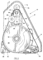
- the housing 12 contains a main drum or roll 30, defining a roll axis and mounted on a central axle 32.
- the axle 32 is rotatably mounted in suitable bearings (not shown), in a sleeve extending from one side wall of the housing.
- the apparatus according to the invention incorporates a tension roller system, which is essentially the same as that shown in U.S. Letters Patent 5,341,605 issued August 13, 1994, Inventor: James Tasikas
- two front wheels 36-36 (Fig. 5) are provided, beneath the motor housing 14.
- One of wheels 36 is adjustable in a manner well known in the art, to level the main roll.
- a third single guide wheel 38 is provided beneath the vacuum housing 16, adjacent the lower end of the handle 22.
- the guide wheel 38 is swingable for steering and is connected to the lower end of the handle 22. The operator can easily guide the machine and steer it, by rotating the rear wheel guide 38 about a vertical axis from side to side.
- a dust catcher blade 40 is provided adjacent the main roll 30, connected by to the vacuum housing 16. In this way, as the roll 30 rotates, dust will be sucked up by the dust catcher, and collected in the bag 20.
- a tension roller 42 is mounted upon an axle 44, which is supported on a mounting bracket 46, by means of bearing mounts 48 at each end. Bolts pass through the free ends of axle 44, securing the axle 44 at its two free ends, to the mounts 48.
- a mounting column 50 extends downwardly.
- Column 50 is mounted at the free end of a cantilever arm 54.
- the opposite end of arm 52 is provided with an elongated cylindrical sliding body 54 extending upwardly therefrom, and extending downwardly therefrom, a spring retention boss 56.
- Sliding body 54 is received in a cylindrical bearing sleeve 58, and is slidable upwardly and downwardly against the pressure of a spring 60.
- Sleeve 58 is pivotally mounted, by two pivot bolts 62 (only one is shown) which in turn pass through arms 64. Arms 64 are secured to a mounting plate 66. Mounting plate 66 is bolted to the interior surface of the side wall of the housing 12, by any suitable bolts 68.
- the sleeve 58 is swingable, through a relatively modest arc, on pivot bolts 62.
- an adjustment bolt 70 is provided in order to procure adjustable swinging movement of the sleeve 58.
- Bolt 70 passes through a threaded bore in plate 66, and engages the lower end of the sleeve 58.
- Bolt 70 extends through the housing, so that it is accessible from the exterior of the machine. Rotation of the bolt 70 in one direction will cause the lower end of the sleeve 58 to swing outwardly away from the plate 66, and rotation of the screw in the reverse direction will permit it to swing back again.
- any angular adjustment can be readily made to the tilt angle of the roller 42, that is tilting its axis relative to the main drum 30 by operating the bolt 70 from the exterior of the machine (shown in phantom in Fig. 3). This may be required to accommodate variations in the length of the belt, or minor variations in the length of the belt from one side to the other.
- the tension roller 42 can be moved towards and away from the main roll 30, the cylindrical body 54 is slidable within the sleeve 58 against the pressure of the spring 60.
- crank pin 74 is mounted on crank pin 74.
- crank pin 74 is in turn mounted on rotatable rod 76.
- An operating arm 78 passes through the free end of the rod 76 on the exterior of the machine, so as to permit an operator to rotate rod 76, thereby forcing the cam 72 against the top of the cylindrical body 54 and forcing the cylindrical body 54 downwardly against the spring 60.
- the sanding belt B is extended around a third extension roll assembly indicated generally as 90 (Figs. 2 and 4).
- the extension roll assembly 90 functions to cause the belt B to run around a generally triangular path, with the portion of the belt extending between the extension roll assembly 90 and the main roll 30, being generally planar and level with the surface to be sanded.
- the purpose of this is to provide a contact area of the sanding belt, on the working surface, which is essentially rectangular in configuration, so as to avoid the disadvantages of prior art belt sanders, and drum sanders, in which the contact with the work surface was essentially a line or tangent.
- the ability to easily remove the belt B from one side is especially important in a large, floor-operating sander because the weight of the sander does not allow the unit to be easily picked up and manipulated. Further, the ability to easily remove the belt B without removing any other parts makes it easier for any person to operate the sander.
- the housing 12 defines a side access door 92, mounted on hinges 94 and swingable outwardly and, in fact, being capable of being completely removed from the hinges for simplicity.
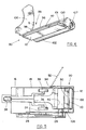
- the extension roll assembly 90 comprises a transverse mounting arm or support plate 96, having two side frame members 98 and 100.
- the side frame member 98 is attached to a mounting end 99 of the support plate 96 and the side frame member 100 is attached to a free end 101 of the support plate 96.
- the two side frame members 98-100 support between them an extension roll 102, having an axle 104 extending there through and supported in the side frames 98-100 by bearings 105 and 107.
- a mounting frame or attachment plate 106 is connected to the plate 96 at the mounting end 99 thereof such that the support plate 96 is supported in a cantilever fashion.
- the attachment plate 106 is, in fact, formed integrally therewith and is bolted to the inside of the housing 12.
- the extension roll 102 is a free running roll and simply provides a means for guiding the sanding belt B along a generally linear path away from the main roll 30.
- the sanding belt B extends freely between the extension roll 102 and the tension roll 42 at the front of the apparatus so as to be free of contact with the main roll 30 in this region.
- a control bar 110 is attached to the plate 96, and is adapted to contact and engage on its underside, the inside surface of the sanding belt B between the main roll 30 and the extension roll 102.
- an anti-friction pad 112 secured to the underside of the control bar 110.
- the belt will pass over the anti-friction pad and there will be a minimum friction between the pad and the belt.
- the anti-friction pad 112 is formed of a type of thermoplastics material which reduces friction, and thus prevents the build up of heat between the belt and the control bar 110. It will be appreciated that in this region the function of the control bar 110 and anti-friction pad 112 is to hold that area of the belt B substantially planar, so as to bring it into contact with a substantial area, typically a rectangular area, on a work piece. This then produces the desired smooth even sanding finish on the work piece.
- the main drum In operation, as the main drum rotates in a clockwise direction (Fig. 2), it will drive the sanding belt B around the tension roller 42 and then around the extension roll 102, and underneath the anti-friction pad 112. This will then cause contact between the sanding belt B and the working surface, on this example a hardwood floor, over a substantial generally planar rectangular surface area of the sanding belt, and thereby avoiding the disadvantages associated with the line or tangent contact engagement, experienced with prior art belt sanders.
Landscapes
- Engineering & Computer Science (AREA)
- Mechanical Engineering (AREA)
- Finish Polishing, Edge Sharpening, And Grinding By Specific Grinding Devices (AREA)
Applications Claiming Priority (2)
| Application Number | Priority Date | Filing Date | Title |
|---|---|---|---|
| US294674 | 1999-04-19 | ||
| US09/294,674 US6155917A (en) | 1999-04-19 | 1999-04-19 | Belt sander with control bar |
Publications (2)
| Publication Number | Publication Date |
|---|---|
| EP1048402A2 true EP1048402A2 (fr) | 2000-11-02 |
| EP1048402A3 EP1048402A3 (fr) | 2002-10-30 |
Family
ID=23134442
Family Applications (1)
| Application Number | Title | Priority Date | Filing Date |
|---|---|---|---|
| EP00303099A Withdrawn EP1048402A3 (fr) | 1999-04-19 | 2000-04-12 | Ponceuse à bande |
Country Status (3)
| Country | Link |
|---|---|
| US (1) | US6155917A (fr) |
| EP (1) | EP1048402A3 (fr) |
| CA (1) | CA2299651C (fr) |
Cited By (1)
| Publication number | Priority date | Publication date | Assignee | Title |
|---|---|---|---|---|
| EP1716972A1 (fr) * | 2005-04-28 | 2006-11-02 | sia Abrasives Industries AG | Insert pour patin de ponçage |
Families Citing this family (4)
| Publication number | Priority date | Publication date | Assignee | Title |
|---|---|---|---|---|
| US6866570B2 (en) | 2003-05-09 | 2005-03-15 | John P. Hunter, Jr. | Variable speed reciprocating linear sliding dual floor sander |
| US7435160B2 (en) * | 2006-03-10 | 2008-10-14 | Marrs Iii Glenn L | Automated floor sander |
| MX391706B (es) | 2011-05-20 | 2025-03-21 | Shaw Ind Group Inc | Dispositivo, sistema y metodo de lijadora de patron. |
| US11491606B2 (en) * | 2015-10-21 | 2022-11-08 | ST Engineering Aerospace Ltd. | Grinding module, a grinding machine and a method for grinding |
Family Cites Families (7)
| Publication number | Priority date | Publication date | Assignee | Title |
|---|---|---|---|---|
| US1804523A (en) * | 1927-12-17 | 1931-05-12 | American Floor Surfacing Mach | Edging machine |
| US2655770A (en) * | 1951-03-19 | 1953-10-20 | Parovel Giovanni | Bowling alley resurfacing machine |
| US3312116A (en) * | 1965-04-12 | 1967-04-04 | Black & Decker Mfg Co | Guiding pulley means for belt sander |
| US3789552A (en) * | 1972-09-12 | 1974-02-05 | Singer Co | Tracking mechanism for belt sanders |
| US3983664A (en) * | 1975-11-21 | 1976-10-05 | Ronald Martin | Belt-type sander attachment for portable power drills |
| US5403229A (en) * | 1992-02-06 | 1995-04-04 | Seli; John | Foot pad extender for a belt sander |
| US5224301A (en) * | 1992-03-20 | 1993-07-06 | James Tasikas | Dual mode floor sander |
-
1999
- 1999-04-19 US US09/294,674 patent/US6155917A/en not_active Expired - Lifetime
-
2000
- 2000-02-25 CA CA002299651A patent/CA2299651C/fr not_active Expired - Lifetime
- 2000-04-12 EP EP00303099A patent/EP1048402A3/fr not_active Withdrawn
Cited By (2)
| Publication number | Priority date | Publication date | Assignee | Title |
|---|---|---|---|---|
| EP1716972A1 (fr) * | 2005-04-28 | 2006-11-02 | sia Abrasives Industries AG | Insert pour patin de ponçage |
| EP2189243A3 (fr) * | 2005-04-28 | 2010-09-08 | sia Abrasives Industries AG | Insert pour patin de ponçage |
Also Published As
| Publication number | Publication date |
|---|---|
| CA2299651C (fr) | 2004-05-04 |
| US6155917A (en) | 2000-12-05 |
| CA2299651A1 (fr) | 2000-10-19 |
| EP1048402A3 (fr) | 2002-10-30 |
Similar Documents
| Publication | Publication Date | Title |
|---|---|---|
| US5341605A (en) | Dual mode floor sander | |
| US6494772B1 (en) | Floor conditioning system | |
| US4177609A (en) | Automatic belt centering device | |
| US5575710A (en) | Leveling mechanism for floor sanders | |
| US3570190A (en) | Belt sanding and polishing machine | |
| CA2299651C (fr) | Ponceuse a courroie comprenant une barre de commande | |
| US3619949A (en) | Miniature belt grinder | |
| EP0543905A1 (fr) | Dispositif de meulage, polissage etc. de pieces a usiner. | |
| US4038784A (en) | Method and apparatus for cross grain abrading to produce a rough-sawn effect | |
| CA2037567C (fr) | Ponceuse a bande, avec cache-poussiere pivotant | |
| JPH027789B2 (fr) | ||
| US10766116B2 (en) | Hand-held sanding device with continuous rotating belt | |
| US5964654A (en) | Multiple abrasive belt machine | |
| US4231193A (en) | Vertical belt sanding apparatus | |
| US2677922A (en) | Finishing and polishing equipment | |
| DE102005027414B3 (de) | Parkettschleifmaschine | |
| US4727683A (en) | Abrasive belt machine | |
| RU2278772C1 (ru) | Шлифовальный станок | |
| JP2916366B2 (ja) | サンディングマシン | |
| JP2512330Y2 (ja) | ベルトサンダ―機の研削装置 | |
| JP2576899Y2 (ja) | ベルトサンダー機の研削装置 | |
| JP2651629B2 (ja) | ベルトサンダー機 | |
| US3482358A (en) | Belt sanders | |
| JPH1128671A (ja) | 油圧式エレベーターのプランジャー研磨装置 | |
| CN219189717U (zh) | 一种砂带机 |
Legal Events
| Date | Code | Title | Description |
|---|---|---|---|
| PUAI | Public reference made under article 153(3) epc to a published international application that has entered the european phase |
Free format text: ORIGINAL CODE: 0009012 |
|
| AK | Designated contracting states |
Kind code of ref document: A2 Designated state(s): AT BE CH CY DE DK ES FI FR GB GR IE IT LI LU MC NL PT SE |
|
| AX | Request for extension of the european patent |
Free format text: AL;LT;LV;MK;RO;SI |
|
| 17P | Request for examination filed |
Effective date: 20010424 |
|
| PUAL | Search report despatched |
Free format text: ORIGINAL CODE: 0009013 |
|
| AK | Designated contracting states |
Kind code of ref document: A3 Designated state(s): AT BE CH CY DE DK ES FI FR GB GR IE IT LI LU MC NL PT SE |
|
| AX | Request for extension of the european patent |
Free format text: AL;LT;LV;MK;RO;SI |
|
| AKX | Designation fees paid |
Designated state(s): AT BE CH CY DE DK ES FI FR GB GR IE IT LI LU MC NL PT SE |
|
| 17Q | First examination report despatched |
Effective date: 20031008 |
|
| STAA | Information on the status of an ep patent application or granted ep patent |
Free format text: STATUS: THE APPLICATION IS DEEMED TO BE WITHDRAWN |
|
| 18D | Application deemed to be withdrawn |
Effective date: 20040219 |