EP1048414A1 - Anzieh-steuervorrichtung für drehschlag-schrauber - Google Patents
Anzieh-steuervorrichtung für drehschlag-schrauber Download PDFInfo
- Publication number
- EP1048414A1 EP1048414A1 EP99906476A EP99906476A EP1048414A1 EP 1048414 A1 EP1048414 A1 EP 1048414A1 EP 99906476 A EP99906476 A EP 99906476A EP 99906476 A EP99906476 A EP 99906476A EP 1048414 A1 EP1048414 A1 EP 1048414A1
- Authority
- EP
- European Patent Office
- Prior art keywords
- pressure chamber
- pressure
- relief valve
- clamping
- hydraulic
- Prior art date
- Legal status (The legal status is an assumption and is not a legal conclusion. Google has not performed a legal analysis and makes no representation as to the accuracy of the status listed.)
- Withdrawn
Links
Images



Classifications
-
- B—PERFORMING OPERATIONS; TRANSPORTING
- B25—HAND TOOLS; PORTABLE POWER-DRIVEN TOOLS; MANIPULATORS
- B25B—TOOLS OR BENCH DEVICES NOT OTHERWISE PROVIDED FOR, FOR FASTENING, CONNECTING, DISENGAGING OR HOLDING
- B25B21/00—Portable power-driven screw or nut setting or loosening tools; Attachments for drilling apparatus serving the same purpose
- B25B21/02—Portable power-driven screw or nut setting or loosening tools; Attachments for drilling apparatus serving the same purpose with means for imparting impact to screwdriver blade or nut socket
-
- B—PERFORMING OPERATIONS; TRANSPORTING
- B25—HAND TOOLS; PORTABLE POWER-DRIVEN TOOLS; MANIPULATORS
- B25B—TOOLS OR BENCH DEVICES NOT OTHERWISE PROVIDED FOR, FOR FASTENING, CONNECTING, DISENGAGING OR HOLDING
- B25B21/00—Portable power-driven screw or nut setting or loosening tools; Attachments for drilling apparatus serving the same purpose
- B25B21/007—Attachments for drilling apparatus for screw or nut setting or loosening
-
- B—PERFORMING OPERATIONS; TRANSPORTING
- B25—HAND TOOLS; PORTABLE POWER-DRIVEN TOOLS; MANIPULATORS
- B25B—TOOLS OR BENCH DEVICES NOT OTHERWISE PROVIDED FOR, FOR FASTENING, CONNECTING, DISENGAGING OR HOLDING
- B25B23/00—Details of, or accessories for, spanners, wrenches, screwdrivers
- B25B23/14—Arrangement of torque limiters or torque indicators in wrenches or screwdrivers
- B25B23/145—Arrangement of torque limiters or torque indicators in wrenches or screwdrivers specially adapted for fluid operated wrenches or screwdrivers
- B25B23/1453—Arrangement of torque limiters or torque indicators in wrenches or screwdrivers specially adapted for fluid operated wrenches or screwdrivers for impact wrenches or screwdrivers
Definitions
- the present invention relates to a clamping control unit for hydraulic pulse wrench, and more particularly to a clamping control unit for hydraulic pulse wench which has particularly a simple construction and by which a clamping torque can be controlled in high precision.
- reference numeral 51 designates a cylinder casing
- 52 denotes a main shaft disposed inside the cylinder casing 51.
- the cylinder casing 51 is adapted to be rotatively driven by means of an air motor, and further a distal end portion of the main shaft 52 is adapted to be engaged with members to be damped such as bolts, and nuts.
- an oil cylinder 53 is formed, and a sectional contour thereof has a shape wherein a pair of circular arcs juxtaposed to a slightly eccentric position from the rotational center of the main shaft 52 are smoothly aligned to each other so as to form an elliptical configuration. Sealed portions 53a, 53b, 53c and 53d each extending along the axial direction of the oil cylinder are defined at substantially quadrisected positions on the inner circumferential surface of the oil cylinder 53. Although it is not shown in the figures, the oil cylinder 53 is filled with a hydraulic operating fluid.
- a proximal end portion of the main shaft 52 is inserted and disposed in the oil cylinder 53, and at the same time a blade groove 54 is defined on the site corresponding thereto, a pair of blades 55, 55 being placed slidably in the blade groove 54.
- These blades 55, 55 are energized by means of a spring 56 (FIG. 5) so as to project outwardly in the diametrical direction thereof, whereby distal end portions of the respective blades 55, 55 are adapted to be slidably in contact with the inner circumferential wall of the above described oil cylinder 50.
- seal portions 52a and 52b are formed at positions intersecting at right angles with respect to the respective blades 55, 55.
- a bypass passage 57 is defined in the cylinder casing 51.
- a valve shaft insertion hole 58 is bored on the cylinder easing 51 so as to be across the bypass passage 57, and a valve shaft 59 is inserted in the insertion hole 58.
- FIG. 5 is a longitudinally sectional view showing a pulse generation mechanism.
- a communication path 60 for allowing to penetrate the bypass passage 57 is formed on the valve shaft 59.
- the communication path 60 functions as a variable aperture wherein a flow passage area of the communication path varies by adjusting a position of the valve shaft 59 in the axial direction thereof. More specifically, when a flow passage area of the communication path 60 is varied, the peak pressure of a pulsed high pressure produced in the high pressure chamber H is adjusted, whereby a clamping torque is controlled. For instance, when the flow passage area is reduced, high peak pressure is produced, and as a result, a high clamping torque is obtained.
- a relief valve 61 is mounted on a shaft end portion on the distal side of the valve shaft 59.
- the relief valve 61 has a structure wherein a ball 62 is pressed to be contact with a shaft end surface of the valve shaft 59 by means of a spring 63 in which a pressure of a hydraulic operating fluid in the communication path 60 acts upon the ball 62 through a pressure leading path 64 defined in a shaft center portion of the valve shaft 59, so that the pressure is opposed to a force of the spring 63.
- a secondary side of the relief valve 61 communicates with a cylinder chamber 65 formed on a top cover.
- a piston 66 is contained, and an automatic shutoff mechanism (not shown) is operated by a movement of the piston 66 by way of a rod 67.
- the relief valve 61 is opened against a force of the spring 63, so that the hydraulic operating fluid relieved as a result of opening the relief valve 61 flows into the cylinder chamber 65 to push the piston 66, whereby the automatic shutoff mechanism is operated through the rod 67.
- supply of air to the air motor is stopped as a result of operation of the automatic shutoff mechanism, so that clamping operation is ceased.
- Adjustment of a clamping torque in the above described hydraulic pulse wrench is carried out by such a manner that the valve shaft 59 is transferred in the axial direction, whereby a flow path-area of the communication passage 60 is adjusted, and at the same time, a spring force of the spring 63 in the relief valve 61 is adjusted.
- the valve shaft 59 is transferred to the right side in FIG. 5 to increase a degree of opening of an aperture diaphragm in the communication path 60, whereby the peak pressure of hydraulic operating fluid produced in the high pressure chamber H is increased, while the spring 63 of the relief valve 61 is compressed to set a relief pressure to a high value.
- two characteristic values i.e., the peak pressure of a hydraulic operating fluid in the high pressure chamber H and a spring force in the relief valve 61 are changed.
- the peak pressure and the spring force vary with the same characteristics as that of the original state in response to transfer of the valve shaft 59, there is no problem.
- both the peak pressure and the spring force have a certain degree of correlativity, they do not vary with quite same characteristics.
- the relief valve does not operate, so that it is forecasted that a situation where a unit does not function arises.
- the relief valve 61 is opened before a predetermined peak pressure is attained in the case where a sufficient spring force is not obtained, so that there is a possibility wherein a desired clamping torque is not achieved.
- the present invention has been made to eliminate the above described disadvantages involved in the prior art, and an object of the invention is to provide a clamping control unit for hydraulic pulse wrench which has a simple construction and by which clamping torque can be controlled with high precision.
- a hydraulic pulse wrench which is provided with a clamping torque generating mechanism 20 driven by an air motor 11, the clamping torque generating mechanism 20 being provided with a cylinder casing 21 and a main shaft 22, either of the cylinder casing 21 and the main shaft 22 being rotatively driven by the air motor 11, while the rest of either of the cylinder casing 21 and the main shaft 22 being constructed so as to engage with a member to be clamped, an oil cylinder 23 disposed in the cylinder casing 21 being filled with a hydraulic operating fluid, at the same time, a blade 25 being mounted to the main shaft 22, whereby the blade 25 is disposed relatively rotatable inside the oil cylinder 23, and a high pressure chamber H for containing the hydraulic operating fluid being formed at a specific position in the rotating direction of the oil cylinder 23 and the blade 25 on either side of the blade, while a low pressure chamber L having a lower pressure than that of the high pressure chamber being formed on the opposite side of the blade, whereby a clamping torque is applied to the member to be clamped; a
- the clamping control unit for hydraulic pulse wrench when the peak pressure produced in the high pressure chamber H reaches a predetermined value of pressure and a pressure of the hydraulic operating fluid in the pressure leading path 28 exceeds a relief pressure in the relief valve 31, the relief valve 31 is opened, the automatic shutoff mechanism 41 is operated by means of a pressure of the hydraulic operating fluid which has been relieved on the secondary side of the relief valve 31 thereby to stop air supply to the air motor 11, so that a clamping operation is automatically stopped. Regulation of a clamping torque may be carried out by adjusting a relief pressure in the relief valve 31 by the relief pressure regulating means 43. As described above, since only a relief pressure of the relief valve 31 may be regulated for adjusting a clamping torque, it becomes possible to control a clamping torque with high precision in a simple structure.
- a clamping control unit for hydraulic pulse wrench is characterized in that a fixed aperture diaphragm 27b is disposed also at a position located on a nearer side to the low pressure chamber L than that of the branched section of the pressure leading path 28 in the bypass passage 27.
- an intermediate pressure produced between two fixed aperture diaphragms 27a and 27b is supplied to the relief valve 31, and a torque is controlled with this pressure, so that it becomes possible to control the torque with high precision.
- FIG. 2 shows a whole schematic construction of the clamping control unit for hydraulic pulse wrench wherein the hydraulic pulse wrench is provided with a grip section 1 and a main body casing 10 extending in a horizontal direction in FIG. 2 on the upper end of the grip section 1.
- the grip section 1 is provided with an air intake port 2 and an operating lever 3.
- a rear side portion of the main body casing 10 contains a vane type air motor 11, while a front side portion thereof contains a clamping torque generating mechanism 20.
- the clamping torque generating mechanism 20 is driven by a rotor 12 of the air motor 11. From the extreme end portion of the main body casing 10, a main shaft 22 extends, and an attachment section for a socket (not shown) and the like is formed on a distal end thereof.
- the clamping torque generating mechanism 20 may be the substantially same one as a conventional mechanism wherein a cylinder casing 21 and a main shaft 22 disposed therein are contained, the cylinder casing 21 is adapted to be rotatively driven by a rotor 12 of an air motor 11, and further a distal end portion of the main shaft 22 is adapted to be engaged with a member to be clamped such as a bolt, and a nut.
- a member to be clamped such as a bolt, and a nut.
- an oil cylinder 23 is formed, and a sectional contour thereof has a shape wherein a pair of circular arce juxtaposed to a slightly eccentric position from the rotational center of the main shaft 22 are smoothly aligned to each other so as to form an elliptical configuration.
- Sealed portions 23a, 23b, 23c and 23d each extending along the axial direction of the oil cylinder 23 are defined at substantially quadrisected positions on the inner circumferential surface of the oil cylinder 23.
- the oil cylinder 23 is filled with a hydraulic operating fluid.
- a proximal end portion of the main shaft 22 is inserted in and disposed on the oil cylinder 23, and at the same time a blade groove 24 is defined on the site corresponding thereto, a pair of blades 25, 25 being placed slidably in the blade groove 24.
- These blades 25, 25 are energized by means of a spring 26 (FIGS.
- seal portions 22a and 22b are formed at positions intersecting at right angles with respect to the respective blades 25, 25.
- a bypass passage 27 is formed so as to communicate the high pressure chamber H with the low pressure chamber L constructed as described above.
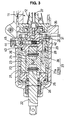
- the bypass passage 27 is composed of a pair of fixed aperture diaphragms 27a, 27b and a part of a pressure leading path 28. More specifically, the pressure leading path 28 is defined in a manner extending along the axial direction of the cylinder casing 21 as shown in FIG. 3. Furthermore, as shown in FIG. 1, a passage with a small diameter is defined as the fixed aperture diameter 27a, while a passage with a small diameter is defined as the fixed aperture diaphragm 27b so as to communicate the pressure leading path 28 with the low pressure chamber L.
- the pressure leading path 28 is further led to a top cover 29 of the oil cylinder 23 as shown in FIG.
- the pressure leading path 28 is connected to a primary side of a relief valve 31 inside the top cover 29.
- the relief valve 31 is provided with a ball 32 and a spring 33, and they are constructed in such that the ball 32 is allowed to press against and to be contact with an opening of the pressure leading path 28 by means of a force of a spring 33.
- a cylinder chamber 35 is defined at the shaft center position of the top cover 23 of the oil cylinder 23, and the cylinder chamber 35 is communicated with a secondary side of the relief valve 31.
- the cylinder chamber communicates with a spring chamber 34 wherein the spring 33 is disposed.
- a piston 36 is placed, and a rod 37 is coupled on the piston 36.
- the rod 37 passes through the shaft center portion of the rotor 12 of the air motor 11, and the rod extends to the rear end portion thereof. As shown in FIG. 2, the rear end portion abuts upon a ball valve 38.
- the ball valve 38 presses and energizes a ball 40 together with the rod 37 towards the extreme end side.
- the ball valve 38 is opened at the time when the ball is forcibly moved against a force of the spring 39, whereby air is supplied to an automatic shutoff mechanism 41, so that the automatic shutoff mechanism 41 is operated.
- the relief valve 31 has a structure wherein a primary port 42, the ball 32, and the spring 33 are juxtaposed to each other in the top cover 29 along the diametrical direction thereof in which the spring 33 is pressed against the primary port 42 by means of a plug 43.
- the plug 43 functions as a means for regulating relief pressure, and which is screwed with the top cover 29 in a manner capable of advancing and retreating in the diametrical direction thereof, so that it can be operated from the outside of the top cover 29 in the diametrical direction thereof.
- an operating hole 44 is defined on the main body casing 10 at the corresponding position thereof so as to be capable of operating the plug 43 from outside the main body casing 10.
- Reference numeral 45 designates a stopper for closing the operating hole 44 in the case when the plug 43 is not operated.
- a spring force of the spring 33 in the relief valve 33 may be adjusted for changing a setting value of clamping torque. More specifically, a screwed position of the plug 43 pressing the spring 33 is adjusted thereby adjusting a length of the sprang 33, and as a result, a relief pressure in the relief valve 31 may be allowed to change.
- clamping control unit for hydraulic pulse wrench is not limited to the above described embodiment, but a variety of modifications may be applied.
- the automatic shutoff mechanism 41 has been operated by an operation of the relief valve 31 by way of the piston 36, the rod 27 and the like, any of other well-known manners may be substituted therefore.
Landscapes
- Engineering & Computer Science (AREA)
- Mechanical Engineering (AREA)
- Details Of Spanners, Wrenches, And Screw Drivers And Accessories (AREA)
Applications Claiming Priority (3)
| Application Number | Priority Date | Filing Date | Title |
|---|---|---|---|
| JP31396798A JP3401544B2 (ja) | 1998-10-15 | 1998-10-15 | 油圧式パルスレンチの締付制御装置 |
| JP31396798 | 1998-10-15 | ||
| PCT/JP1999/000858 WO2000021719A1 (en) | 1998-10-15 | 1999-02-24 | Clamping control device of hydraulic pulse |
Publications (2)
| Publication Number | Publication Date |
|---|---|
| EP1048414A1 true EP1048414A1 (de) | 2000-11-02 |
| EP1048414A4 EP1048414A4 (de) | 2007-05-02 |
Family
ID=18047649
Family Applications (1)
| Application Number | Title | Priority Date | Filing Date |
|---|---|---|---|
| EP99906476A Withdrawn EP1048414A4 (de) | 1998-10-15 | 1999-02-24 | Anzieh-steuervorrichtung für drehschlag-schrauber |
Country Status (6)
| Country | Link |
|---|---|
| US (1) | US6334494B1 (de) |
| EP (1) | EP1048414A4 (de) |
| JP (1) | JP3401544B2 (de) |
| KR (1) | KR20010024714A (de) |
| CN (1) | CN1287521A (de) |
| WO (1) | WO2000021719A1 (de) |
Cited By (2)
| Publication number | Priority date | Publication date | Assignee | Title |
|---|---|---|---|---|
| SE2230372A1 (en) * | 2022-11-17 | 2024-01-09 | Atlas Copco Ind Technique Ab | Power tool comprising a hydraulic pulse unit |
| US12466038B2 (en) | 2019-10-29 | 2025-11-11 | Atlas Copco Industrial Technique Ab | Socket for a tightening tool |
Families Citing this family (31)
| Publication number | Priority date | Publication date | Assignee | Title |
|---|---|---|---|---|
| JP4712170B2 (ja) * | 2000-08-28 | 2011-06-29 | 瓜生製作株式会社 | トルクコントロールレンチのシャットオフバルブ機構 |
| US6708778B2 (en) * | 2001-01-12 | 2004-03-23 | Makita Corporation | Hydraulic unit with increased torque |
| US6581697B1 (en) * | 2002-01-28 | 2003-06-24 | Chicago Pneumatic Tool Company | Power impact tool torque apparatus |
| US6626610B1 (en) * | 2002-04-02 | 2003-09-30 | Ben L. Seegmiller | Cable bolt apparatus and method of installation for mines |
| US6902011B2 (en) | 2003-05-23 | 2005-06-07 | Fci Americas Technology, Inc. | Variable torque impact wrench |
| JP4008865B2 (ja) * | 2003-08-01 | 2007-11-14 | 株式会社東洋空機製作所 | 締付具 |
| TWM257933U (en) * | 2004-05-13 | 2005-03-01 | Chu Dai Ind Co Ltd | Leaking air pressure for a pneumatic tool |
| US20060237205A1 (en) * | 2005-04-21 | 2006-10-26 | Eastway Fair Company Limited | Mode selector mechanism for an impact driver |
| EP1920887B1 (de) * | 2006-11-13 | 2009-12-23 | Cooper Power Tools GmbH & Co. | Werkzeug mit einem Hydraulikschlagwerk |
| EP1920888B1 (de) * | 2006-11-13 | 2011-04-20 | Cooper Power Tools GmbH & Co. | Impulswerkzeug und zugehörige Vorderplatte |
| ES2335911T3 (es) * | 2006-11-13 | 2010-04-06 | COOPER POWER TOOLS GMBH & CO. | Herramienta de impulso. |
| EP2036679B1 (de) * | 2007-09-11 | 2012-07-11 | Uryu Seisaku Ltd. | Vorrichtung zur Einstellung des Schlagmoments eines hydraulischen Drehmomentschlüssels |
| JP5126515B2 (ja) * | 2008-05-08 | 2013-01-23 | 日立工機株式会社 | オイルパルス工具 |
| JP5347699B2 (ja) * | 2009-05-08 | 2013-11-20 | 日立工機株式会社 | オイルパルス工具 |
| SE535186C2 (sv) * | 2010-05-12 | 2012-05-15 | Atlas Copco Tools Ab | Mutterdragare med hydraulisk pulsenhet |
| JP5547004B2 (ja) * | 2010-09-07 | 2014-07-09 | 瓜生製作株式会社 | 油圧式トルクレンチの打撃トルク調節装置 |
| JP5248567B2 (ja) * | 2010-09-27 | 2013-07-31 | 瓜生製作株式会社 | トルクコントロールレンチのシャットオフバルブ機構 |
| JP5556542B2 (ja) * | 2010-09-29 | 2014-07-23 | 日立工機株式会社 | 電動工具 |
| US8939227B2 (en) | 2010-12-23 | 2015-01-27 | Caterpillar Inc. | Pressure protection valve for hydraulic tool |
| TWI416015B (zh) * | 2011-04-12 | 2013-11-21 | Hyphone Machine Ind Co Ltd | 氣動馬達 |
| JP6145993B2 (ja) * | 2012-11-07 | 2017-06-14 | マックス株式会社 | オイルパルス工具 |
| JP5376189B1 (ja) * | 2013-05-22 | 2013-12-25 | ヨコタ工業株式会社 | 衝撃締付工具 |
| US9878435B2 (en) | 2013-06-12 | 2018-01-30 | Makita Corporation | Power rotary tool and impact power tool |
| TW201406501A (zh) * | 2013-10-31 | 2014-02-16 | Quan-Zheng He | 氣動工具的衝擊組 |
| TWI498194B (zh) * | 2014-05-30 | 2015-09-01 | Tranmax Machinery Co Ltd | Impact drive |
| TWM562747U (zh) | 2016-08-25 | 2018-07-01 | 米沃奇電子工具公司 | 衝擊工具 |
| JP7055291B2 (ja) * | 2017-08-21 | 2022-04-18 | 不二空機株式会社 | 締付トルク発生機構及び油圧パルスレンチ |
| JP6762572B2 (ja) * | 2017-08-31 | 2020-09-30 | 瓜生製作株式会社 | 油圧式トルクレンチの打撃トルク発生装置 |
| JP6816866B2 (ja) * | 2018-10-03 | 2021-01-20 | 瓜生製作株式会社 | 油圧式トルクレンチの打撃トルク調節装置 |
| EP4011559B1 (de) * | 2020-12-09 | 2025-01-29 | Dubuis et Cie | Vorrichtung mit einem schnellkupplungssystem zur befestigung eines austauschbaren kopfs |
| CN112388552B (zh) * | 2021-01-21 | 2021-05-04 | 杭州雷恩智能制造有限公司 | 基于油压波形相似度对比的液压棘轮扳手自动判停方法 |
Family Cites Families (7)
| Publication number | Priority date | Publication date | Assignee | Title |
|---|---|---|---|---|
| DE3170928D1 (en) * | 1981-07-17 | 1985-07-18 | Giken Kogyo Kk | Fluid impulse torque tool |
| US4920836A (en) * | 1986-11-28 | 1990-05-01 | Yokota Industrial Co., Ltd. | Two blade type impulse wrench |
| US5217079A (en) * | 1987-05-05 | 1993-06-08 | Cooper Industries, Inc. | Hydro-impulse screwing device |
| JPH0223964U (de) * | 1988-07-29 | 1990-02-16 | ||
| DE69022626T2 (de) * | 1989-05-15 | 1996-03-21 | Uryu Seisaku Ltd | Drucküberwachungsmittel für Drehmoment-Schraubenschlüssel. |
| JP2509216Y2 (ja) * | 1989-05-15 | 1996-08-28 | 瓜生製作株式会社 | トルクコントロ―ルレンチの圧力検出装置 |
| US5544710A (en) * | 1994-06-20 | 1996-08-13 | Chicago Pneumatic Tool Company | Pulse tool |
-
1998
- 1998-10-15 JP JP31396798A patent/JP3401544B2/ja not_active Expired - Lifetime
-
1999
- 1999-02-24 KR KR1020007006481A patent/KR20010024714A/ko not_active Ceased
- 1999-02-24 CN CN99801836A patent/CN1287521A/zh active Pending
- 1999-02-24 EP EP99906476A patent/EP1048414A4/de not_active Withdrawn
- 1999-02-24 WO PCT/JP1999/000858 patent/WO2000021719A1/ja not_active Ceased
-
2000
- 2000-06-15 US US09/594,373 patent/US6334494B1/en not_active Expired - Fee Related
Cited By (3)
| Publication number | Priority date | Publication date | Assignee | Title |
|---|---|---|---|---|
| US12466038B2 (en) | 2019-10-29 | 2025-11-11 | Atlas Copco Industrial Technique Ab | Socket for a tightening tool |
| SE2230372A1 (en) * | 2022-11-17 | 2024-01-09 | Atlas Copco Ind Technique Ab | Power tool comprising a hydraulic pulse unit |
| SE545774C2 (en) * | 2022-11-17 | 2024-01-09 | Atlas Copco Ind Technique Ab | Power tool comprising a hydraulic pulse unit |
Also Published As
| Publication number | Publication date |
|---|---|
| JP2000117650A (ja) | 2000-04-25 |
| KR20010024714A (ko) | 2001-03-26 |
| US6334494B1 (en) | 2002-01-01 |
| EP1048414A4 (de) | 2007-05-02 |
| CN1287521A (zh) | 2001-03-14 |
| WO2000021719A1 (en) | 2000-04-20 |
| JP3401544B2 (ja) | 2003-04-28 |
Similar Documents
| Publication | Publication Date | Title |
|---|---|---|
| EP1048414A1 (de) | Anzieh-steuervorrichtung für drehschlag-schrauber | |
| EP0398655B1 (de) | Drucküberwachungsmittel für Drehmoment-Schraubenschlüssel | |
| JPS6158273B2 (de) | ||
| US6179063B1 (en) | Impulse wrench | |
| EP0309625B1 (de) | Hydraulischer Impuls-Schraubenschlüssel | |
| EP0186316A1 (de) | Tragbarer und kraftbetriebener Impulsschrauber | |
| KR20070110521A (ko) | 유량 조정 기구를 갖는 유량 제어 장치 | |
| US4243111A (en) | Automatic shut-off valve for power tools | |
| US5346021A (en) | Fastening tool having improved pressure regulator device | |
| US6286641B1 (en) | Oil brake | |
| GB2106024A (en) | Control for pneumatic tool eg a screwdriver | |
| JP3122686B2 (ja) | トルク制御装置付き動力レンチ | |
| EP1067321B1 (de) | Flüssigkeitsdosierventil | |
| JP4876973B2 (ja) | 内接歯車ポンプ | |
| JP2509216Y2 (ja) | トルクコントロ―ルレンチの圧力検出装置 | |
| US20040067148A1 (en) | Functionalties of axially movable spool valve | |
| JP3380848B2 (ja) | トルクコントロールレンチのシャットオフバルブ機構 | |
| EP1579106B1 (de) | Hoch geschwindigkeitsdruckluftmotor mit druckaktiviertem drehzahlregler | |
| US4318334A (en) | Torque control for a fluid operated motor | |
| JPS6217663Y2 (de) | ||
| JP3668314B2 (ja) | 油圧式パルスレンチ | |
| JP7106110B2 (ja) | 締付トルク発生機構及び油圧式パルスレンチ | |
| JPS629789B2 (de) | ||
| JPS6231255Y2 (de) | ||
| JP2727395B2 (ja) | 油圧式インパクトレンチのトルク制御装置 |
Legal Events
| Date | Code | Title | Description |
|---|---|---|---|
| PUAI | Public reference made under article 153(3) epc to a published international application that has entered the european phase |
Free format text: ORIGINAL CODE: 0009012 |
|
| 17P | Request for examination filed |
Effective date: 20000711 |
|
| AK | Designated contracting states |
Kind code of ref document: A1 Designated state(s): DE FR GB SE |
|
| A4 | Supplementary search report drawn up and despatched |
Effective date: 20070222 |
|
| 17Q | First examination report despatched |
Effective date: 20080620 |
|
| R17C | First examination report despatched (corrected) |
Effective date: 20080621 |
|
| GRAP | Despatch of communication of intention to grant a patent |
Free format text: ORIGINAL CODE: EPIDOSNIGR1 |
|
| STAA | Information on the status of an ep patent application or granted ep patent |
Free format text: STATUS: THE APPLICATION IS DEEMED TO BE WITHDRAWN |
|
| 18D | Application deemed to be withdrawn |
Effective date: 20090901 |