EP1048505A2 - Lüfterhaube für Fahrzeug und Komponentenkühlmodul - Google Patents
Lüfterhaube für Fahrzeug und Komponentenkühlmodul Download PDFInfo
- Publication number
- EP1048505A2 EP1048505A2 EP00201229A EP00201229A EP1048505A2 EP 1048505 A2 EP1048505 A2 EP 1048505A2 EP 00201229 A EP00201229 A EP 00201229A EP 00201229 A EP00201229 A EP 00201229A EP 1048505 A2 EP1048505 A2 EP 1048505A2
- Authority
- EP
- European Patent Office
- Prior art keywords
- air
- fan
- cooling
- radiator
- component
- Prior art date
- Legal status (The legal status is an assumption and is not a legal conclusion. Google has not performed a legal analysis and makes no representation as to the accuracy of the status listed.)
- Granted
Links
- 238000001816 cooling Methods 0.000 title claims abstract description 48
- 239000003570 air Substances 0.000 claims abstract description 69
- 239000012080 ambient air Substances 0.000 claims abstract description 7
- 230000008901 benefit Effects 0.000 claims description 10
- 238000004378 air conditioning Methods 0.000 claims description 2
- 238000011144 upstream manufacturing Methods 0.000 abstract description 6
- 239000000463 material Substances 0.000 description 6
- 239000012530 fluid Substances 0.000 description 5
- 230000000694 effects Effects 0.000 description 3
- 239000002991 molded plastic Substances 0.000 description 3
- 230000000712 assembly Effects 0.000 description 2
- 238000000429 assembly Methods 0.000 description 2
- 230000009286 beneficial effect Effects 0.000 description 1
- 230000006835 compression Effects 0.000 description 1
- 238000007906 compression Methods 0.000 description 1
- 238000010276 construction Methods 0.000 description 1
- 239000002826 coolant Substances 0.000 description 1
- 239000007788 liquid Substances 0.000 description 1
- 239000002184 metal Substances 0.000 description 1
- 238000000034 method Methods 0.000 description 1
- 239000004033 plastic Substances 0.000 description 1
- 229920003023 plastic Polymers 0.000 description 1
- 230000000717 retained effect Effects 0.000 description 1
Images



Classifications
-
- F—MECHANICAL ENGINEERING; LIGHTING; HEATING; WEAPONS; BLASTING
- F28—HEAT EXCHANGE IN GENERAL
- F28F—DETAILS OF HEAT-EXCHANGE AND HEAT-TRANSFER APPARATUS, OF GENERAL APPLICATION
- F28F9/00—Casings; Header boxes; Auxiliary supports for elements; Auxiliary members within casings
- F28F9/001—Casings in the form of plate-like arrangements; Frames enclosing a heat exchange core
- F28F9/002—Casings in the form of plate-like arrangements; Frames enclosing a heat exchange core with fastening means for other structures
-
- B—PERFORMING OPERATIONS; TRANSPORTING
- B60—VEHICLES IN GENERAL
- B60K—ARRANGEMENT OR MOUNTING OF PROPULSION UNITS OR OF TRANSMISSIONS IN VEHICLES; ARRANGEMENT OR MOUNTING OF PLURAL DIVERSE PRIME-MOVERS IN VEHICLES; AUXILIARY DRIVES FOR VEHICLES; INSTRUMENTATION OR DASHBOARDS FOR VEHICLES; ARRANGEMENTS IN CONNECTION WITH COOLING, AIR INTAKE, GAS EXHAUST OR FUEL SUPPLY OF PROPULSION UNITS IN VEHICLES
- B60K11/00—Arrangement in connection with cooling of propulsion units
- B60K11/02—Arrangement in connection with cooling of propulsion units with liquid cooling
- B60K11/04—Arrangement or mounting of radiators, radiator shutters, or radiator blinds
Definitions
- This invention relates generally to vehicle engine cooling fan shrouds and vehicle underhood component cooling devices.
- Vehicles with liquid cooled engines generally mount the engine cooling heat exchanger (radiator) at the front of the engine compartment, just behind the bumper and grille, so as to take advantage of the ram air effect at higher vehicle speeds.
- an axially acting engine cooling fan forces air through the radiator.
- the fan is generally mounted to a support shroud that both physically secures the fan to the vehicle, and which also surrounds the fan to confine and direct the air efficiently through the radiator.
- radiators are typically planar, rectangular structures, the fans are invariably circular, with blades extending radially from a central hub. The inefficiency resulting from this inevitable radiator-fan shape mismatch is reduced by the air ducting action of the shroud, and can be further reduced by using two, side by side fans.
- the air drawn through the radiator is significantly heated above ambient temperature, typically as much as 80 degrees F above ambient temperature.
- Vehicles that also have an air conditioning system generally mount a condenser in front of the radiator. Since condensers operate at significantly lower temperatures than the radiator, it would not be practical to mount them behind the radiator. Therefore, air that is forced through the radiator first flows through the condenser, and is raised in temperature far less, only on the order of 10 degrees F above ambient.
- Fan and fan shroud location in actual commercial practice, is almost invariably behind the radiator, so as to pull air through both the condenser and radiator.
- the fan and fan shroud materials must obviously be designed to withstand the higher, downstream radiator air temperatures.
- An obviously cooler location would be upstream, in front of both the condenser and radiator, but this location is invariably rejected due to vulnerability to damage, and, in the case of engine belt driven fans, inaccessibility to the belt.
- USPN 4,510,991 discloses a fan mounted to the drive shaft of a motor that is mounted to or through the condenser, thereby putting the fan itself between the condenser and radiator.
- Various novel circular condenser designs better matched to the shape of the fan are disclosed, but there is no particular recognition that the location of the fan is beneficial in terms of cooler air.
- More recent USPN 5,771,961 proposes similar designs, also fixing the drive motors to the condenser face, and potentially even placing the fan itself within a very large and ill defined through hole in the condenser. Doing this would remove so much condenser volume and area as to render it essentially unworkable.
- the disclosure also speaks in terms of eliminating the fan shroud, although air confinement rings surrounding the fan are disclosed, which would be necessary to proper fan air ducting and routing. As a practical matter, any proposal that required a drastic redesign of the standard condenser would not find any significant commercial use.
- USPN 5,671,802 discloses a hose and box system that houses a heat producing component and routes ram air from the front of the vehicle through the box. This utilizes ambient air temperature for cooling, but, of course, can provide no forced cooling air when the vehicle is idling.
- USPN 5,775,450 provides essentially the converse in terms of benefit and shortcomings.
- a scoop behind the fan diverts some of the fan forced air up and over the alternator, cooling it whenever the fan is running, but using air that has been heated by the radiator significantly above ambient temperature.
- There are components for which each system will work perfectly well that is, those that do not need a continual stream of air, or which can benefit from cooling even by warmer air.
- there are underhood components that would potentially benefit both from a continual supply of forced cooling air, especially if the air were cooler than the air that has already passed through the radiator.
- a combined vehicle fan shroud and component cooling module in accordance with the present invention is characterized by the features specified in claim 1.
- the condenser and radiator are of conventional size, and planar shape, both mounted in front of the vehicle engine compartment in a spaced and preferably parallel configuration.
- a circular, axially acting engine cooling fan is mounted between the two heat exchangers, to a shroud that both physically secures the fan to the vehicle and which surrounds at least part of the fan blade periphery so as to confine and duct air through the radiator, after it has been pulled through the condenser.
- a zone of higher than ambient pressure air is created downstream of the fan.
- the fan shroud also serves to confine and conduct air pulled through the condenser, creating an additional zone of lower than ambient pressure air upstream of the fan. In both pressure zones, the air has been warmed only by the condenser, and not the radiator.
- the cooler air quality conveniently allows the shroud to be manufactured from less thermally resistant, but more malleable materials, such as blow molded plastics, if desired.
- the vehicle also contains at least one component, such as a battery or the like, that would benefit from a forced cooling air stream.
- a cooling air duct opens into the rear, higher pressure air zone, so as to capture a portion of the higher pressure air and direct it out and to the component to actively and continually cool it with forced, relatively low temperature air.
- the duct can easily be incorporated into the fan shroud embodiment disclosed, since it can be conveniently made of more easily molded materials.
- return air duct can be routed from the cooled component back to the lower pressure air zone, creating a complete forced cooling air loop.
- the front end of a conventional vehicle indicated generally at 10 has a covered engine compartment 12 located behind a grill opening 14, through which ambient air flows in the direction indicated by the arrows.
- the grill opening 14 is backed by a rigid, generally rectangular front end structure, including an upper rail 16, lower rail 18, and connecting side rails 20. These provide the basic structural foundation for the physical mounting of other front end located structures.
- a component indicated schematically at 22, which is meant to indicate any component, be it a battery, generator, heat producing electrical component, or other that is in need of, or could at least benefit from, active cooling.
- a standard radiator 26 and condenser 28 are both basically planar and rectangular structures, with no special feature. As in a typical vehicle, they are mounted to the vehicle front end, just behind the grill opening 14, with the condenser in front. This exposes each to ambient ram air, for maximum cooling.
- the radiator 26 and condenser 28 are preferably mounted parallel to one another, though exact parallelism is not necessary, and spaced from one another by a typical distance of about a hundred millimeters. In general, everything about the size, location and relative location of the two heat exchangers is conventional, which adds greatly to the commercial potential of the invention.
- shroud 30 is preferably rectangular in outline, and rigid enough to be secured to and between the rails 16, 18 and 20, and thereby serve as a secure foundation for other components, including the radiator and condenser 26 and 28.
- the shroud 30 could be manufactured by several different means, and with different materials. As an example only, it could be compression molded plastic, blow molded plastic, fabricated or stamped metal, or even a metal-plastic hybrid structure. While the material and process can be varied, the basic location of shroud 30, upstream of radiator 28, allows the material used to be one that is less heat resistant, and also allows other heat sensitive components to be mounted to it, in the same general location.
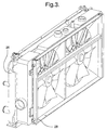
- shroud 30 is basically a double walled, hollow frame, with at least one, and preferably a pair of side by side, hoop like fan rings 32.
- Each ring 32 centrally supports a central hub and stator assembly 34.
- the hub and stator assemblies 34 are rigid enough to support fans and motors, described further below, but, with their spoke like configuration, do not substantially block air flow therethrough.
- At least one tube 36 on the radiator side of shroud 30 opens through a fan ring 32.
- another tube 38 can open through a fan ring 32 on the condenser side of shroud 30.
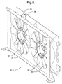
- shroud 30 the relation of shroud 30 to other components mounted thereto is illustrated.
- the condenser 28 and radiator 26 can be mounted to opposite sides of the shroud 30, and are in the embodiment disclosed.
- hollow, shape matched fluid containers 40 can be mounted, to contain any fluid, such as radiator coolant overflow, windshield washer fluid, reserve power steering fluid, etc. This uses space that would otherwise be wasted, with no ill effect on air flow, and with minimal effect on the fluid, given the relatively cool location.
- Low profile electric fan drive motors 42 are fixed centrally within the hub and stator assemblies 34, and conventional axial air fans 44 are fixed to each of these.
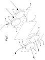
- module 24 is illustrated in a schematic fashion.
- the general locations of the condenser 28 and radiator 26 are indicated by dotted planes.
- the location of the shroud 30 is illustrated by a dotted central plane C, which would bisect the fan rings 32 into upstream and downstream halves. This is done to demarcate distinct pressure zones.
- the fans 44 spin outside air is pulled in through grill opening 14 and initially through condenser 28, where it is heated only about 10 degrees F above ambient temperature. The drawn in air is ducted and guided axially through the fan rings 32.
- the air pressure would be lower than ambient, because of the pulling action of the fans 44.
- This upstream or front zone is indicated at F.
- the air pressure would be higher than ambient, because of the pushing action of the fans 44.
- This downstream or rear zone is indicated at R.
- the tube 36 opens through one fan ring 32 and into the higher pressure rear zone R, while tube 38 opens into the lower pressure front zone F.
- Tube 36 would provide an escape or outlet for a portion of the pressurized air from zone R, which flow is indicated by the out arrow.
- the air flowing out of outlet tube 36 could be ducted by a hose or line to the component 22, or to a box containing the component 32, to actively cool it.
- the cooling air could simply be dumped back to ambient at that point, or, it could instead be routed in a loop back to the inlet tube 38, and into the lower pressure zone F. Either way, pressurized air that had been heated only by the condenser 28, and not yet by the radiator 26, would be provided for active component cooling, at minimal extra cost, and with minimal additional space occupied.
- a component in need of cooling such as a power transistor or the like, could be mounted to or near the fan shroud 30, with an opening direct through the fan ring(s) 32 to either (or both) the pressure zones R or F. Air would then be pulled through, or pushed through, or forced in a complete loop, directly through the component.
- hoses or duct work to route the air, it is possible that local ambient air could simply be pulled through or around the component 22 by routing the hose or duct from it and only into the low pressure front zone F. This would work if the pressure were low enough to create enough suction. Therefore, it will be understood that it is not intended to limit the invention to just the embodiment disclosed.
Landscapes
- Engineering & Computer Science (AREA)
- Mechanical Engineering (AREA)
- Physics & Mathematics (AREA)
- Thermal Sciences (AREA)
- General Engineering & Computer Science (AREA)
- Chemical & Material Sciences (AREA)
- Combustion & Propulsion (AREA)
- Transportation (AREA)
- Cooling, Air Intake And Gas Exhaust, And Fuel Tank Arrangements In Propulsion Units (AREA)
Applications Claiming Priority (2)
| Application Number | Priority Date | Filing Date | Title |
|---|---|---|---|
| US299504 | 1999-04-26 | ||
| US09/299,504 US6155335A (en) | 1999-04-26 | 1999-04-26 | Vehicle fan shroud and component cooling module |
Publications (3)
| Publication Number | Publication Date |
|---|---|
| EP1048505A2 true EP1048505A2 (de) | 2000-11-02 |
| EP1048505A3 EP1048505A3 (de) | 2003-04-23 |
| EP1048505B1 EP1048505B1 (de) | 2005-04-06 |
Family
ID=23155096
Family Applications (1)
| Application Number | Title | Priority Date | Filing Date |
|---|---|---|---|
| EP00201229A Expired - Lifetime EP1048505B1 (de) | 1999-04-26 | 2000-04-04 | Lüfterhaube für Fahrzeug und Komponentenkühlmodul |
Country Status (3)
| Country | Link |
|---|---|
| US (1) | US6155335A (de) |
| EP (1) | EP1048505B1 (de) |
| DE (1) | DE60019186T2 (de) |
Cited By (8)
| Publication number | Priority date | Publication date | Assignee | Title |
|---|---|---|---|---|
| WO2007039004A1 (de) * | 2005-09-30 | 2007-04-12 | Behr Gmbh & Co. Kg | Anordnung zur befestigung von wärmeübertragern, insbesondere für ein kraftfahrzeug |
| FR2901352A1 (fr) * | 2006-05-17 | 2007-11-23 | Air Liquide | Dispositif de refroidissement par echange thermique force avec un fluide tel que de l'air et pile a combustible comportant un tel dispositif |
| CN102001279A (zh) * | 2009-08-31 | 2011-04-06 | 现代自动车株式会社 | 用于燃料电池汽车的冷却系统 |
| WO2012045674A3 (de) * | 2010-10-08 | 2012-08-30 | Robert Bosch Gmbh | Kühlmodul |
| FR2976528A1 (fr) * | 2011-06-20 | 2012-12-21 | Renault Sa | Procede et dispositif d'assemblage d'un groupe moto ventilateur et d'un radiateur pour un moteur de vehicule automobile, et ensemble de groupe moto ventilateur et radiateur obtenu. |
| KR101459431B1 (ko) * | 2009-12-04 | 2014-11-07 | 현대자동차 주식회사 | 차량용 쿨링 장치 |
| US11326506B2 (en) | 2019-07-03 | 2022-05-10 | Ford Global Technologies, Llc | Vehicle fan shroud with integrated support structure |
| US20220388367A1 (en) * | 2021-06-03 | 2022-12-08 | Brose Fahrzeugteile SE & Co. Kommanditgesellschaft, Würzburg | Cooling pack assembly |
Families Citing this family (58)
| Publication number | Priority date | Publication date | Assignee | Title |
|---|---|---|---|---|
| JP2001121941A (ja) * | 1999-10-28 | 2001-05-08 | Denso Corp | 熱交換器の車両搭載構造 |
| AU3791001A (en) * | 1999-10-29 | 2001-05-14 | Robert Bosch Corporation | Mount for connecting automotive fan motor to housing |
| US6755157B1 (en) | 1999-10-29 | 2004-06-29 | Robert Bosch Corporation | Mount for connecting automotive fan motor to housing |
| US6883589B2 (en) * | 2000-01-31 | 2005-04-26 | Denso Corporation | Front end structure |
| JP4320899B2 (ja) * | 2000-02-03 | 2009-08-26 | 株式会社デンソー | フロントエンドパネル |
| JP4605849B2 (ja) * | 2000-03-30 | 2011-01-05 | 富士重工業株式会社 | 車体前部構造 |
| US7121368B2 (en) * | 2000-05-09 | 2006-10-17 | Mackelvie Winston | Bi-directional automotive cooling fan |
| DE10052331A1 (de) * | 2000-10-17 | 2002-05-02 | Stribel Gmbh | Lüfteranlage |
| US6708790B2 (en) * | 2001-04-26 | 2004-03-23 | Denso Corporation | Front-end structure of a vehicle |
| EP1255028A3 (de) * | 2001-05-03 | 2005-05-11 | Kautex Textron GmbH & Co. KG. | Blasgeformter Träger |
| DE10132602B4 (de) * | 2001-05-03 | 2004-05-13 | Kautex Textron Gmbh & Co. Kg | Blasgeformter Träger |
| JP2002372389A (ja) * | 2001-06-13 | 2002-12-26 | Denso Corp | 熱交換器 |
| KR20020096278A (ko) * | 2001-06-19 | 2002-12-31 | 현대자동차주식회사 | 자동차의 냉각계 배치구조 |
| LU90827B1 (en) * | 2001-09-07 | 2003-03-10 | Delphi Tech Inc | Assembly of a component of a vehicle air conditioning system to a support structure |
| FR2833235B1 (fr) * | 2001-12-11 | 2004-08-13 | Plastic Omnium Cie | Piece de structure avant de vehicule automobile munie d'un convergent et face avant technique constituant une telle piece de structure |
| US20030160472A1 (en) * | 2002-02-26 | 2003-08-28 | Siemens Canada Limited | Integrated splash shield and air intake system |
| EP1369576B1 (de) * | 2002-06-03 | 2012-02-08 | Siemens VDO Automotive Inc. | Integriertes Motorraumbauelement und Luftansaugsystem |
| US6676371B1 (en) | 2002-08-22 | 2004-01-13 | Custom Molders, Inc. | Double barrel vehicle cooling fan shroud |
| US7055582B2 (en) * | 2002-10-15 | 2006-06-06 | Tecumseh Products Company | Refrigerating unit having heat-exchanger mounting shroud |
| US7137775B2 (en) | 2003-03-20 | 2006-11-21 | Huntair Inc. | Fan array fan section in air-handling systems |
| US7597534B2 (en) | 2003-03-20 | 2009-10-06 | Huntair, Inc. | Fan array fan section in air-handling systems |
| US11255332B2 (en) | 2003-03-20 | 2022-02-22 | Nortek Air Solutions, Llc | Modular fan housing with multiple modular units having sound attenuation for a fan array for an air-handling system |
| JP4127112B2 (ja) * | 2003-04-24 | 2008-07-30 | 株式会社デンソー | 車両のフロントエンド構造 |
| US20050224267A1 (en) * | 2004-04-08 | 2005-10-13 | Callas James J | Cooling system for a vehicular engine |
| US7406835B2 (en) * | 2005-05-10 | 2008-08-05 | Emp Advanced Development, Llc | Cooling system and method for cooling a heat producing system |
| US20060272800A1 (en) * | 2005-06-02 | 2006-12-07 | Paccar Inc | Radiator fan shroud with flow directing ports |
| US20070024135A1 (en) * | 2005-07-26 | 2007-02-01 | Siemens Vdo Automotive Inc. | Electric motor case with folded-out mounting brackets and economical motor-fan packaging |
| DE102005039090A1 (de) * | 2005-08-06 | 2007-02-08 | Behr Gmbh & Co. Kg | Montageträgersystem |
| US20080289794A1 (en) * | 2005-09-12 | 2008-11-27 | Frank Joseph Leitch | Vehicle cooling assembly having a protective screen |
| EP1934485B1 (de) * | 2005-10-12 | 2011-05-04 | Brose Fahrzeugteile GmbH & Co. KG, Würzburg | Kühlerlüftermodul für ein kraftfahrzeug |
| DE102005051158A1 (de) | 2005-10-24 | 2007-04-26 | Delphi Technologies, Inc., Troy | Kühlmodul und Verfahren zum Betrieb eines Kühlmoduls |
| JP2007309608A (ja) * | 2006-05-19 | 2007-11-29 | Daikin Ind Ltd | トレーラー用冷凍装置 |
| KR100802929B1 (ko) * | 2006-05-24 | 2008-02-14 | 현대자동차주식회사 | 자동차 엔진 룸의 외부 공기 흡입 시스템 |
| EP1878602A1 (de) * | 2006-07-15 | 2008-01-16 | Delphi Technologies, Inc. | Kühlmodul eines Fahrzeugs |
| JP4986685B2 (ja) * | 2007-03-30 | 2012-07-25 | 本田技研工業株式会社 | 自動2輪車用エンジンの冷却装置 |
| US20080251040A1 (en) * | 2007-04-11 | 2008-10-16 | Continental Automotive Canada Inc. | Engine cooling structure having fan module sandwiched between condenser and radiator |
| US7640897B2 (en) * | 2007-08-08 | 2010-01-05 | Sauer-Danfoss, Inc. | Fan design and method of operating |
| US20090211285A1 (en) * | 2008-02-26 | 2009-08-27 | Picker Benjamin P | Condensing Unit |
| JP5129712B2 (ja) * | 2008-09-30 | 2013-01-30 | 本田技研工業株式会社 | 自動二輪車のラジエータ取付け構造 |
| JP5199849B2 (ja) * | 2008-12-05 | 2013-05-15 | 三菱重工業株式会社 | 車両用熱交換モジュールおよびこれを備えた車両 |
| SE533313C2 (sv) * | 2008-12-22 | 2010-08-24 | Atlas Copco Rock Drills Ab | Kylsystem avsett för kylning av åtminstone en cirkulerande fluid, samt en maskin innefattande kylsystemet |
| US20100218916A1 (en) * | 2009-02-27 | 2010-09-02 | Ford Global Technolgies, Llc | Plug-in hybrid electric vehicle secondary cooling system |
| DE102009050370A1 (de) | 2009-10-22 | 2011-04-28 | Magna Electronics Europe Gmbh & Co. Kg | Kühlermodul für ein Kraftfahrzeug |
| US8579060B2 (en) * | 2010-01-13 | 2013-11-12 | Demmer Corporation | Double heat exchanger radiator assembly |
| USD663019S1 (en) * | 2011-10-25 | 2012-07-03 | Thomas L Purnell | Shroud component for a temperature control system |
| CN102384676B (zh) * | 2011-10-31 | 2013-05-29 | 陆加孚 | 一种高效空气换热器 |
| DE202011110551U1 (de) * | 2011-12-27 | 2014-08-12 | Brose Fahrzeugteile GmbH & Co. Kommanditgesellschaft, Würzburg | Kühlerzarge und Kühlerverbund |
| EP2620610A1 (de) * | 2012-01-30 | 2013-07-31 | Faurecia Bloc Avant | Motorfahrzeug-Vorderendenträger mit einer länglichen Öffnung und einem Kühlmodul |
| US8701811B2 (en) | 2012-04-30 | 2014-04-22 | Honda Motor Co., Ltd. | Battery cooling system and method |
| KR102026103B1 (ko) * | 2014-09-05 | 2019-09-27 | 한온시스템 주식회사 | 쿨링 모듈 |
| BR102015026378A2 (pt) * | 2014-10-21 | 2017-07-11 | Modine Manufacturing Company | Cooling module with a tank of integrated compensation to him |
| US10661650B2 (en) * | 2016-07-22 | 2020-05-26 | Nimer Ibrahim Shiheiber | Radiator system |
| DE102018219006A1 (de) * | 2018-11-07 | 2020-05-07 | Brose Fahrzeugteile SE & Co. Kommanditgesellschaft, Würzburg | Lüfteranordnung für ein Kraftfahrzeug |
| CN109268127A (zh) * | 2018-12-03 | 2019-01-25 | 安徽全柴动力股份有限公司 | 一种发动机水箱 |
| FR3090508B1 (fr) * | 2018-12-20 | 2022-06-24 | Valeo Systemes Thermiques | Système thermique d’un véhicule automobile |
| US11014440B2 (en) * | 2019-07-29 | 2021-05-25 | Ford Global Technologies, Llc | Structural cooling pack |
| CN112177747A (zh) * | 2020-09-30 | 2021-01-05 | 陈钦展 | 具有液冷辅助散热的汽车冷却风扇 |
| WO2024120641A1 (en) * | 2022-12-08 | 2024-06-13 | Volvo Penta Corporation | Modular cooling system for a power source |
Citations (4)
| Publication number | Priority date | Publication date | Assignee | Title |
|---|---|---|---|---|
| US4510991A (en) | 1982-05-31 | 1985-04-16 | Mitsubishi Denki Kabushiki Kaisha | Heat exchanger and fan motor in a front wheel drive vehicle |
| US5671802A (en) | 1995-10-05 | 1997-09-30 | General Motors Corporation | Electronic control module cooling device |
| US5771961A (en) | 1995-08-03 | 1998-06-30 | Valeo Thermique Moteur | Fan module |
| US5775450A (en) | 1996-05-06 | 1998-07-07 | General Motors Corporation | Vehicle underhood component cooling system |
Family Cites Families (7)
| Publication number | Priority date | Publication date | Assignee | Title |
|---|---|---|---|---|
| US2104394A (en) * | 1935-03-07 | 1938-01-04 | Gen Motors Corp | Heating and ventilating of passenger cars |
| US3203499A (en) * | 1962-06-08 | 1965-08-31 | Caterpillar Tractor Co | Cooling arrangement for supercharged engines |
| US4351162A (en) * | 1980-10-01 | 1982-09-28 | Wallace Murray Corp. | Apparatus for engine cooling and vehicle air conditioning |
| US5526872A (en) * | 1993-10-22 | 1996-06-18 | Ford Motor Company | Airflow ejector for an automotive vehicle |
| US5588482A (en) * | 1994-09-26 | 1996-12-31 | Ford Motor Company | Ducted cooling system for an automotive vehicle |
| US5671803A (en) * | 1995-10-23 | 1997-09-30 | General Motors Corporation | Modular condenser and fan shroud assembly |
| US5649587A (en) * | 1996-02-23 | 1997-07-22 | Mccord Winn Textron, Inc. | Fan shroud and receptacle arrangement |
-
1999
- 1999-04-26 US US09/299,504 patent/US6155335A/en not_active Expired - Lifetime
-
2000
- 2000-04-04 EP EP00201229A patent/EP1048505B1/de not_active Expired - Lifetime
- 2000-04-04 DE DE60019186T patent/DE60019186T2/de not_active Expired - Lifetime
Patent Citations (4)
| Publication number | Priority date | Publication date | Assignee | Title |
|---|---|---|---|---|
| US4510991A (en) | 1982-05-31 | 1985-04-16 | Mitsubishi Denki Kabushiki Kaisha | Heat exchanger and fan motor in a front wheel drive vehicle |
| US5771961A (en) | 1995-08-03 | 1998-06-30 | Valeo Thermique Moteur | Fan module |
| US5671802A (en) | 1995-10-05 | 1997-09-30 | General Motors Corporation | Electronic control module cooling device |
| US5775450A (en) | 1996-05-06 | 1998-07-07 | General Motors Corporation | Vehicle underhood component cooling system |
Cited By (13)
| Publication number | Priority date | Publication date | Assignee | Title |
|---|---|---|---|---|
| WO2007039004A1 (de) * | 2005-09-30 | 2007-04-12 | Behr Gmbh & Co. Kg | Anordnung zur befestigung von wärmeübertragern, insbesondere für ein kraftfahrzeug |
| FR2901352A1 (fr) * | 2006-05-17 | 2007-11-23 | Air Liquide | Dispositif de refroidissement par echange thermique force avec un fluide tel que de l'air et pile a combustible comportant un tel dispositif |
| CN102001279A (zh) * | 2009-08-31 | 2011-04-06 | 现代自动车株式会社 | 用于燃料电池汽车的冷却系统 |
| CN102001279B (zh) * | 2009-08-31 | 2016-03-16 | 现代自动车株式会社 | 用于燃料电池汽车的冷却系统 |
| KR101459431B1 (ko) * | 2009-12-04 | 2014-11-07 | 현대자동차 주식회사 | 차량용 쿨링 장치 |
| WO2012045674A3 (de) * | 2010-10-08 | 2012-08-30 | Robert Bosch Gmbh | Kühlmodul |
| WO2012175831A3 (fr) * | 2011-06-20 | 2013-02-28 | Renault S.A.S. | Procede et dispositif d'assemblage d'un groupe moto ventilateur et d'un radiateur pour un moteur de vehicule automobile et ensemble de groupe moto ventilateur et radiateur obtenu |
| US8960619B2 (en) | 2011-06-20 | 2015-02-24 | Renault S.A.S. | Method and device for assembling a motor-fan unit and a radiator for a motor vehicle engine and motor-fan unit and radiator assembly obtained |
| FR2976528A1 (fr) * | 2011-06-20 | 2012-12-21 | Renault Sa | Procede et dispositif d'assemblage d'un groupe moto ventilateur et d'un radiateur pour un moteur de vehicule automobile, et ensemble de groupe moto ventilateur et radiateur obtenu. |
| RU2589229C2 (ru) * | 2011-06-20 | 2016-07-10 | Рено С.А.С. | Способ и устройство соединения вентиляторного агрегата и радиатора для двигателя автотранспортного средства и полученный узел вентиляторного агрегата и радиатора |
| US11326506B2 (en) | 2019-07-03 | 2022-05-10 | Ford Global Technologies, Llc | Vehicle fan shroud with integrated support structure |
| US20220388367A1 (en) * | 2021-06-03 | 2022-12-08 | Brose Fahrzeugteile SE & Co. Kommanditgesellschaft, Würzburg | Cooling pack assembly |
| US11951797B2 (en) * | 2021-06-03 | 2024-04-09 | Brose Fahrzeugteile SE & Co. Kommanditgesellschaft, Würzburg | Cooling pack assembly |
Also Published As
| Publication number | Publication date |
|---|---|
| US6155335A (en) | 2000-12-05 |
| EP1048505A3 (de) | 2003-04-23 |
| EP1048505B1 (de) | 2005-04-06 |
| DE60019186D1 (de) | 2005-05-12 |
| DE60019186T2 (de) | 2005-09-22 |
Similar Documents
| Publication | Publication Date | Title |
|---|---|---|
| US6155335A (en) | Vehicle fan shroud and component cooling module | |
| KR102567146B1 (ko) | 차량용 쿨링모듈 | |
| US6512347B1 (en) | Battery having an integral cooling system | |
| US8919300B2 (en) | Vehicle with fan unit producing an amplified air flow to a heat exchanger | |
| EP0868597A1 (de) | Totaler kühlungszusammenbau für kraftfahrzeuge, die mit brennkraftmaschinen angetrieben werden | |
| US20020014322A1 (en) | Front end structure | |
| US20100096208A1 (en) | Radiator coil mounted on a motorcycle | |
| EP1694948A1 (de) | Wärmetauscherpaket mit geteiltem ladeluftkühler | |
| CN100519242C (zh) | 燃料电池车辆的冷却装置 | |
| US20210070131A1 (en) | Continuous cooling assembly | |
| CN110001370B (zh) | 一种氢能源汽车的分布式散热器 | |
| JP4323307B2 (ja) | 車両用熱交換器システム | |
| US20170030250A1 (en) | Compact cooling module | |
| CN108973655A (zh) | 车辆用冷却模块 | |
| CN114502403A (zh) | 用于机动车辆的冷却设备 | |
| KR20110061216A (ko) | 콘덴서-인터쿨러 일체형 쿨링모듈 구조 | |
| CN111301153A (zh) | 发动机冷却总成 | |
| US6676371B1 (en) | Double barrel vehicle cooling fan shroud | |
| WO2022042582A1 (en) | Cooling system for an electric vehicle | |
| CN114340935A (zh) | 车辆的热交换装置 | |
| EP1167165B1 (de) | Vorderbau | |
| EP3832157B1 (de) | Motordämpferkühlung unter verwendung des kreislaufs der klimaanlage | |
| US20090065171A1 (en) | Cooling system for a motor vehicle | |
| US20240017586A1 (en) | Cooling module for an electric or hybrid motor vehicle, having a tangential-flow turbomachine | |
| CN220363192U (zh) | 冷却装置布置结构、车载空调系统和新能源汽车 |
Legal Events
| Date | Code | Title | Description |
|---|---|---|---|
| PUAI | Public reference made under article 153(3) epc to a published international application that has entered the european phase |
Free format text: ORIGINAL CODE: 0009012 |
|
| AK | Designated contracting states |
Kind code of ref document: A2 Designated state(s): AT BE CH CY DE DK ES FI FR GB GR IE IT LI LU MC NL PT SE |
|
| AX | Request for extension of the european patent |
Free format text: AL;LT;LV;MK;RO;SI |
|
| PUAL | Search report despatched |
Free format text: ORIGINAL CODE: 0009013 |
|
| AK | Designated contracting states |
Designated state(s): AT BE CH CY DE DK ES FI FR GB GR IE IT LI LU MC NL PT SE |
|
| AX | Request for extension of the european patent |
Extension state: AL LT LV MK RO SI |
|
| 17P | Request for examination filed |
Effective date: 20031023 |
|
| AKX | Designation fees paid |
Designated state(s): DE FR GB |
|
| GRAP | Despatch of communication of intention to grant a patent |
Free format text: ORIGINAL CODE: EPIDOSNIGR1 |
|
| GRAS | Grant fee paid |
Free format text: ORIGINAL CODE: EPIDOSNIGR3 |
|
| GRAA | (expected) grant |
Free format text: ORIGINAL CODE: 0009210 |
|
| AK | Designated contracting states |
Kind code of ref document: B1 Designated state(s): DE FR GB |
|
| REG | Reference to a national code |
Ref country code: GB Ref legal event code: FG4D |
|
| REG | Reference to a national code |
Ref country code: IE Ref legal event code: FG4D |
|
| REF | Corresponds to: |
Ref document number: 60019186 Country of ref document: DE Date of ref document: 20050512 Kind code of ref document: P |
|
| ET | Fr: translation filed | ||
| PLBE | No opposition filed within time limit |
Free format text: ORIGINAL CODE: 0009261 |
|
| STAA | Information on the status of an ep patent application or granted ep patent |
Free format text: STATUS: NO OPPOSITION FILED WITHIN TIME LIMIT |
|
| 26N | No opposition filed |
Effective date: 20060110 |
|
| PG25 | Lapsed in a contracting state [announced via postgrant information from national office to epo] |
Ref country code: GB Free format text: LAPSE BECAUSE OF NON-PAYMENT OF DUE FEES Effective date: 20060404 |
|
| GBPC | Gb: european patent ceased through non-payment of renewal fee |
Effective date: 20060404 |
|
| REG | Reference to a national code |
Ref country code: DE Ref legal event code: R082 Ref document number: 60019186 Country of ref document: DE Representative=s name: BRP RENAUD UND PARTNER MBB RECHTSANWAELTE PATE, DE Ref country code: DE Ref legal event code: R082 Ref document number: 60019186 Country of ref document: DE Representative=s name: BRP RENAUD UND PARTNER MBB, DE Ref country code: DE Ref legal event code: R081 Ref document number: 60019186 Country of ref document: DE Owner name: MAHLE INTERNATIONAL GMBH, DE Free format text: FORMER OWNER: DELPHI TECHNOLOGIES, INC., TROY, MICH., US |
|
| REG | Reference to a national code |
Ref country code: FR Ref legal event code: PLFP Year of fee payment: 17 |
|
| REG | Reference to a national code |
Ref country code: FR Ref legal event code: PLFP Year of fee payment: 18 |
|
| REG | Reference to a national code |
Ref country code: FR Ref legal event code: TP Owner name: MAHLE INTERNATIONAL GMBH, DE Effective date: 20180103 |
|
| REG | Reference to a national code |
Ref country code: FR Ref legal event code: PLFP Year of fee payment: 19 |
|
| PGFP | Annual fee paid to national office [announced via postgrant information from national office to epo] |
Ref country code: FR Payment date: 20190429 Year of fee payment: 20 |
|
| PGFP | Annual fee paid to national office [announced via postgrant information from national office to epo] |
Ref country code: DE Payment date: 20190628 Year of fee payment: 20 |
|
| REG | Reference to a national code |
Ref country code: DE Ref legal event code: R071 Ref document number: 60019186 Country of ref document: DE |