EP1048593A2 - Chaíne de convoyeur à rouleaux - Google Patents
Chaíne de convoyeur à rouleaux Download PDFInfo
- Publication number
- EP1048593A2 EP1048593A2 EP00303390A EP00303390A EP1048593A2 EP 1048593 A2 EP1048593 A2 EP 1048593A2 EP 00303390 A EP00303390 A EP 00303390A EP 00303390 A EP00303390 A EP 00303390A EP 1048593 A2 EP1048593 A2 EP 1048593A2
- Authority
- EP
- European Patent Office
- Prior art keywords
- conveyor
- pins
- conveyor member
- link plate
- adjacent
- Prior art date
- Legal status (The legal status is an assumption and is not a legal conclusion. Google has not performed a legal analysis and makes no representation as to the accuracy of the status listed.)
- Withdrawn
Links
Images

Classifications
-
- B—PERFORMING OPERATIONS; TRANSPORTING
- B65—CONVEYING; PACKING; STORING; HANDLING THIN OR FILAMENTARY MATERIAL
- B65G—TRANSPORT OR STORAGE DEVICES, e.g. CONVEYORS FOR LOADING OR TIPPING, SHOP CONVEYOR SYSTEMS OR PNEUMATIC TUBE CONVEYORS
- B65G17/00—Conveyors having an endless traction element, e.g. a chain, transmitting movement to a continuous or substantially-continuous load-carrying surface or to a series of individual load-carriers; Endless-chain conveyors in which the chains form the load-carrying surface
- B65G17/30—Details; Auxiliary devices
- B65G17/38—Chains or like traction elements; Connections between traction elements and load-carriers
- B65G17/42—Attaching load carriers to traction elements
- B65G17/44—Attaching load carriers to traction elements by means excluding relative movements
-
- B—PERFORMING OPERATIONS; TRANSPORTING
- B65—CONVEYING; PACKING; STORING; HANDLING THIN OR FILAMENTARY MATERIAL
- B65G—TRANSPORT OR STORAGE DEVICES, e.g. CONVEYORS FOR LOADING OR TIPPING, SHOP CONVEYOR SYSTEMS OR PNEUMATIC TUBE CONVEYORS
- B65G17/00—Conveyors having an endless traction element, e.g. a chain, transmitting movement to a continuous or substantially-continuous load-carrying surface or to a series of individual load-carriers; Endless-chain conveyors in which the chains form the load-carrying surface
- B65G17/30—Details; Auxiliary devices
- B65G17/38—Chains or like traction elements; Connections between traction elements and load-carriers
- B65G17/42—Attaching load carriers to traction elements
-
- B—PERFORMING OPERATIONS; TRANSPORTING
- B65—CONVEYING; PACKING; STORING; HANDLING THIN OR FILAMENTARY MATERIAL
- B65G—TRANSPORT OR STORAGE DEVICES, e.g. CONVEYORS FOR LOADING OR TIPPING, SHOP CONVEYOR SYSTEMS OR PNEUMATIC TUBE CONVEYORS
- B65G2201/00—Indexing codes relating to handling devices, e.g. conveyors, characterised by the type of product or load being conveyed or handled
- B65G2201/02—Articles
-
- B—PERFORMING OPERATIONS; TRANSPORTING
- B65—CONVEYING; PACKING; STORING; HANDLING THIN OR FILAMENTARY MATERIAL
- B65G—TRANSPORT OR STORAGE DEVICES, e.g. CONVEYORS FOR LOADING OR TIPPING, SHOP CONVEYOR SYSTEMS OR PNEUMATIC TUBE CONVEYORS
- B65G2207/00—Indexing codes relating to constructional details, configuration and additional features of a handling device, e.g. Conveyors
- B65G2207/38—Pin used as carrier of one article
Definitions
- This invention relates to an improved roller conveyor chain, and in particular, to an improved roller conveyor chain that may be used to carry or convey cans.
- Roller conveyor chains with one or more article carrying or conveying members are well known in the prior art.
- Such roller conveyor chains have been useful in conveying cylindrical articles with an open end, such as metal cans, through a curing operation after the can has been painted or has received printing.
- the cans may be printed with an ink that cures upon exposure to ultraviolet light, and the cans may be carried through an ultraviolet curing oven carried on a roller conveyor chain.
- freshly painted or otherwise decorated cans may be carried on a roller conveyor chain through drying ovens.
- Such chain is commonly referred to as oven chain.
- roller chains have pins that extend to pin link plates.
- the pins extend through bushings that are connected to roller link plates inward of the pin link plates. Rollers are around the bushings.
- the prior art has joined article carrying or conveying members to elements of a conventional roller chain.
- some of the pins have been substantially elongated to extend through and out beyond one of the link plates. These elongated pins have been used to carry or convey the cans. The opposite ends of the pins have been mounted with mechanical devices such as cotter pins or spring clips to hold the pin link plate in place.
- detachable article carrying or conveying members have been attached to non-adjacent pins in the roller chain.
- the prior roller conveyor chain designs have been problematic.
- the article carrying or conveying member may not be adequately retained in service. If the conveying member is adequately retained, it may be difficult or time-consuming to remove if the conveying member becomes broken or damaged.
- the retaining mechanisms may add excess cost to the product as well. For some designs, removal and replacement of the article carrying or conveying member may require disassembly of the base chain.
- the present invention provides an article conveying assembly and a chain conveyor as defined by the attached claims.
- the present invention addresses the need for a roller conveyor chain with an article conveying member that is adequately retained in service, and that can be removed and replaced without disassembling the chain.
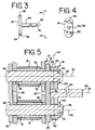
- the present invention provides a roller conveyor chain 10 comprising a base chain 12 and a plurality of article conveyor assemblies 14 spaced around the chain. Two article conveying assemblies are shown in the section of chain illustrated in FIGS. 1-2. It should be understood that a complete chain would typically have several spaced article conveying assemblies, and that the base chain would be connected to form a continuous loop.
- the illustrated base chain 12 is a roller chain that includes conventional rollers 16, bushings 18, pin link plates 20 and roller link plates 22.
- the base chain 12 also includes pins 24.
- the pins 24 include both standard length pins 26 and extended length pins 28.
- the base roller chain 12 comprises repeated pairs of spaced pin link plates 20 separated by repeated pairs of spaced roller link plates 22, as is conventional.
- the spaced roller link plates 22 extend between pairs of adjacent bushings 18.
- the spaced pin link plates 20 extend between pairs of adjacent pins, and each pin link plate 20 extends from one roller link plate to an adjacent roller link plate.
- the spaced roller link plates 22 have aligned holes 30, 32 that receive bushings 18 in a press fit.
- the rollers 16 surround the bushings 18 in a conventional manner.
- the pins 24 extend through the bushings 18.
- the pin link plates have holes 34, 36, and the standard length pins 26 are connected to pairs of spaced pin link plates at the spaced holes 34, 36 in a conventional manner, such as by a press fit or by a slip fit with retaining members, such as cotter pins, spring clips and the like.
- Extended length pins 28 are paired into adjacent pairs and spaced around the chain wherever an article conveying assembly 14 is to be mounted. One pair of the extended length pins 28 may be positioned to extend through the holes 34, 36 of a single pin link plate 20, as shown at the top article conveying assembly 14 of FIGS. 1-2, or one pair of extended length pins 28 may be positioned to extend through the holes 36, 34 of adjacent pin link plates 20, as shown at the bottom article conveying assembly 14 of FIGS. 1-2.
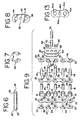
- each extended length pin 28 is connected to the pin link plate 20 in a conventional manner, such as through a press fit in the holes 34, 36, or through a slip fit with retaining members such as cotter pins and the like. As shown in FIGS. 1-2 and 9, each roller link plate 22 extends between two pin link plates 20 to form the continuous chain.
- the roller chain of the present invention is useful in conveying articles such as cans through a processing operation, such as through a drying oven. Cans are shown in phantom in FIG. 2 at 38.
- the article conveying assemblies 14 serve to support the articles such as the illustrated cans for transport with movement of the roller chain.
- each article conveyor assembly 14 of the first embodiment includes a conveyor member 40 and a conveyor member link plate 42.
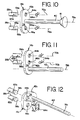
- the embodiments illustrated in FIGS. 10-12 also include a conveyor member 40 and a conveyor member link plate 42a-c.
- Another embodiment of a conveyor member link plate is shown in FIG. 13 at 42d.
- each conveyor member link plate 42 in the first illustrated embodiment has three spaced holes or openings: two end mounting holes or openings 44, 46 and a center conveyor hole or opening 48. Part of each conveyor member 40 is received in the conveyor hole 48 of one conveyor member link plate 42.
- one end mounting opening 44 receives part of one of the adjacent extended length pins 28 and the other end mounting opening 46 receives part of the other adjacent extended length pin 28 to mount the article conveyor assembly 14 on the base chain 12.
- the conveyor hole or opening 48 need not be centered on the conveyor member link plate 42, and that the mounting holes or openings 44, 46 need not be at the ends of the conveyor member link plate 42.
- the conveyor member 40 may comprise a rod, as illustrated, with a free end 50 and an opposite end 52.
- part of the conveyor member 40 at the opposite end 52 is secured in the center conveyor hole or opening 48 of the conveyor member link plate 42 through a press fit, but it should be understood that other forms of connection may be used, such as a slip fit with a retaining member.
- the conveyor member 40 could be secured to the conveyor member link plate 42 through use of an adhesive or through welding. Mechanical fasteners such as screws could be used to secure the elements 40, 42 of the assembly 14 together.
- the conveyor member 40 could be received in a hole or opening that does not extend through the entire thickness of the conveyor member link plate 42.
- the conveyor member 40 and conveyor member link plate 42 could comprise an integral structure. Any of these options may be used as a means for securing the conveyor member 40 to the conveyor member link plate 42 at a position spaced from the two mounting openings 44, 46 for receiving parts of two adjacent extended length pins 28.
- the free end 50 of the conveyor member 40 is spaced furthest from the base chain 12.
- the conveyor member 40 may have any conventional structure: it may have a solid or hollow shaft, with a spring-cushioned member, knob or cap at the free end 50; standard tips and extensions may be used. An example of a cushion member or tip is shown at 51 in FIG. 10.
- the conveyor member may include a sleeve that is placed over a base rod. Instead of a rod or shaft, the conveyor member 40 could comprise a hook, a mandrel, a tray or a pan.
- the conveyor member 40 may have any standard length for the intended application, such as an exposed length beyond the conveyor member link plate 42 of about 7 inches (178mm) and a thickness of about a quarter inch(6mm) or less, exclusive of any tip or extension. It should be understood that the illustrated conveyor members and the above noted dimensions and shapes are provided by way of example only, and that the invention is not limited to these dimensions and shapes.
- each of the conveyor member link plates 42 in the first illustrated embodiment includes an inward piece 54 and an outward piece 56.
- each piece 54, 56 of the link plate 42 has a thickness of 0.094 inches (2.4mm), giving the entire link plate 42 a thickness of 0.188 inches (4.8mm).
- Each piece 54, 56 of the illustrated conveying member link plate 42 has about the same thickness as the other link plates 20, 22.
- the two-piece link plane 42 provides extra thickness to strengthen the junction of the conveying member 40 and the conveying member link plate 42. It should be understood that other structures could be used for the link plate 42, such as a single-ply plate of greater thickness than the other link plates 20, 22, as illustrated in the embodiment of FIG.
- the conveyor member link plates 42 may have shapes other than the illustrated shapes, and that the holes or openings 44, 46 and 48 could be positioned other than as illustrated in the first embodiment.
- FIG. 11 it may be desirable to shape the conveyor member link plates 42 so that two adjacent extended length pins 28b may be received in adjacent mounting holes 44b, 46b in the conveyor member link plate 42b, with the conveyor member 40 extending out from a conveyor opening at an end of the conveyor member link plate 42b adjacent to one of the mounting holes 46b to form the conveying assembly 14b.
- the central longitudinal axes 70b of the two adjacent extended length pins 28b will be adjacent to each other and the central longitudinal axis 76b of the conveyor member 40 will be adjacent to the central longitudinal axis of one of the adjacent pins when assembled.
- the central longitudinal axes 70c of the two adjacent extended length pins 28c will be adjacent to each other and the central longitudinal axis 76c of the conveyor member 40 will be offset from the central longitudinal axes of the adjacent pins when assembled.
- the conveyor member link plate 42d may be shaped like the pin link plates 20 and roller link plates 22, curving inward from the mounting holes 44d, 46d toward the central conveyor hole 48d.
- the embodiment of FIG. 13 may have an inward piece (not shown) and an outward piece 56d, or could comprise a thicker, single layer, as in the embodiments of FIGS. 10-12.
- the central longitudinal axis 76, 76a of the conveying member 40 lies between the central longitudinal axes 70, 70a of the two adjacent pins 28, 28a.
- the base roller chain 12 may be standard pin oven chain or RING LEADER O-Ring Pin Oven Chain available from the Diamond Chain Company of Indianapolis, Indiana, using extended length pins 28 instead of the standard "through pin” design of these commercial products.
- the base chain may be, for example, a standard 3 ⁇ 4 inch (19mm) pitch ANSI chain or industrial RING LEADER O-ring chain available from Diamond Chain, using spaced pairs of extended pins 28 and standard pins 26. Heat treated components may be preferred. If the conveyor chain is to be used in high temperature environments in, for example, drying ovens, it is preferred to incorporate some additional clearances in the base chain to accommodate the high temperatures and allow more access for lubricant to enter the joints between the bushings and pins. It should be understood that these chain products are identified for purposes of illustration only, and that the invention is not limited to these roller chain products.
- the extended length pins 28 have protruding outward ends 58 and inward ends 60.
- the inward ends 60 are received in the holes 34, 36 of the pin link plates 20 in a conventional manner, such as through a press fit, through a slip fit with a retainer, or through any other conventional connection.
- the extended length pins extend through the holes 30, 32 of the roller link plates 22 and outward beyond the roller link plates 22, through the holes 34, 36 of the pin link plates 20 and beyond the pin link plates 20.
- the extended length pins 28a-28c of the other embodiments also have protruding ends 58a-c, and also have inward ends that are connected to pin link plates in a conventional manner.
- the extended length pins 28, 28a-c extend through the mounting holes 44, 44 a-c, 46, 46a-c of the conveyor member link plates 42, 42a-c to the outward ends 58, 58a-c that extend beyond the conveyor member link plates.
- the extended length pins 28, 28a-c are longer than the standard length pins 26; for a 3 ⁇ 4 inch(19mm) pitch chain, the standard length pins 26 may have a length of 0.995 inches (25.3mm) for example, and the extended length pins 28, 28a-c may have a length of 1.299 inches (33.0mm) for example.
- the diameters of the extended length pins 28, 28a-c are smaller than the diameters of the holes or openings 30, 32, 34, 36, 44, 44a-c, 46, 46a-c of the link plates 20, 22, 42 to provide a slip fit. It should be understood that these dimensions are provided by way of example only, and that the invention is not limited to any particular dimension unless expressly set forth in the claims.
- each extended length pin 28 has a recess 62 around its circumference near the outward end 58.
- the recess comprises a groove.
- retainers 64 are used to secure the article conveying assemblies 14 on the extended length pins 28.
- each retainer comprises an e-shaped thin metal member, shown in FIGS. 7 and 9.
- One retainer 64 is slipped onto the outward end 58 of each extended length pin 28 to fit within the groove 62 of each pin 28.
- the conveyor member link plate 42 is restrained between the retainer 64 and the nearest pin link plate 20.
- the retainers 64 may comprise commercially available snap rings, e-clips or similar structures, such as retaining rings sold by Waldes Truarc/ Industrial Retaining Ring Company of Millburn, New Jersey (or Waldes Truarc Inc. of Somerset, New Jersey). It should be understood that other retainers could be used as well, such as cotter pins, shown at 64a-b in FIGS. 10-11, or spring clips, shown at 64c in FIG. 12. All of these retainers are removable, and all of them would allow for each article conveying assembly 14 to be detached individually from the base chain 12 without requiring disassembly of the base chain 12. It should also be understood that the extended length pins 28 would have complementary structures, such as through holes, shown at 63a-b in FIGS. 10-11, if cotter pins are to be used instead of the illustrated grooves 62.
- the base chain 12 and the article conveying assemblies 14 may be separately assembled and then assembled into the complete conveyor chain 10.
- the desired spacing With the desired spacing known, the positions for the article conveying assemblies 14 can be determined. With the positions of the article conveying assemblies 14 known, the necessary positions for the extended length pins 28 can be determined. The extended length pins 28 may be used at these positions and the standard length pins 26 may be used at positions between the pairs of extended length pins 28.
- the base chain may then be assembled in a conventional manner, except that one end of each extended length pin 28 will not yet be secured to the link plate 20. It should be understood that the base chain could alternatively be assembled with all or a substantial number of pins 24 being extended length pins 28, with some form of retainer or mechanical connection to mount them to the pin link plates, and with none or few standard length pins.
- each article conveying assembly 14 a conveyor member 40 with a desired structure is selected, and one end 52 of the conveyor member 40 is then secured to the conveyor member link plate 42.
- the conveyor member 40 may be secured to the conveyor member link plate 42 by press-fitting one end 52 of the conveyor member 40 in the conveyor hole or opening 48 of the conveyor member link plate 42, or through some other means.
- Each assembled article conveying assembly 14 is then mounted to the base chain 12.
- Each conveyor member link plate 42 is mounted on a pair of adjacent extended length pins 28 by placing the outward ends 58 of the extended length pins 28 in the mounting holes or openings 44, 46 of the conveyor member link plate 42 and sliding the conveyor member link plate 42 axially along the extended length pins 28 to the nearest pin link plate 20. Since the mounting holes or openings 44, 46 of the conveyor member link plates 42 have diameters larger than the diameters of the extended length pins 28, the conveyor member link plate 42 may be readily slip fit onto the pair of adjacent extended length pins 28.
- Retainers 64 may then be slipped into the grooves 62 on the extended length pins 28 outward of the conveyor member link plate 42 to removably secure the article conveying assembly 14 to the base chain. If other types of retainers are used, such as cotter pins 64a-b or spring clips 64c as in the embodiments of FIGS. 10-12, the conveying assembly 14a-c may be secured to the base chain in the appropriate manner, such as by slipping cotter pins 64a-b through holes 63a-b near the end of the extended length pins 28a-b, for example, or by slipping a spring clip 64c around both extended length pins 28c and snapping the spring clip into the grooves 62c of both pins 28c.
- retainers such as cotter pins 64a-b or spring clips 64c as in the embodiments of FIGS. 10-12
- the assembled roller conveyor chain 10 may have any appropriate number and spacing of article conveying assemblies 14. As shown in FIGS. 1-2 at the top article conveying assembly 14, the adjacent pair of extended length pins 28 may extend through a single set of aligned pin ink plates 20, or as shown in FIGS. 1-2 at the bottom article conveying assembly 14, the adjacent pair of extended length pins 28 may extend through adjacent sets of pin link plates 20.
- the article conveying assemblies 14 may be attached to the base chain 12 with all of the conveying members 40 extending outward from the same side of the base chain, as shown in FIG. 1. Alternatively, it may be desirable to mount some of the article conveying assemblies 14 on the opposite side of the base chain 12 so that different conveyor members 40 extend out from different sides of the base chain 12.
- the present invention allows for removal and replacement without disassembly of the base chain 12.
- the retainers 64 holding the article conveying assembly 14 with the broken, damaged or worn conveyor member may then be removed, so that this article conveying assembly 14 may be removed as a unit by slipping the assembly off of the extended length pins 28.
- a new article conveyor assembly may then be slip fit onto the same pair of extended length pins 28 and retainers 64 positioned to restrain the new assembly in position on the extended length pins.
- the conveyor chain 10 may be repaired and ready for reuse.
- the same general procedure may be used for the other embodiments of FIGS. 10-13.
- the conveyor member 40 is not co-axial with the extended length pins 28. Instead, as shown in FIG. 5, the central longitudinal axes 70, 72 of the adjacent extended length pins 28 intersect a plane 74 through the conveyor member link plate 42 at locations spaced from the intersection of the central longitudinal axis 76 of the conveyor member 40 and the plane 74. In the first illustrated embodiment, the central longitudinal axes 70, 72, 76 of the extended length pins 28 and conveyor member 40 are parallel to the central longitudinal axis 78 of the standard length pins 26, as shown in FIG. 1. However, it should be understood that the conveyor member 40 could instead be canted to be other than perpendicular to the plane 74.
- the conveyor members 40 are not co-axial with the extended length pins 28a-c. Instead, the central longitudinal axes 70a-c, 72a-c of the adjacent extended length pins 28a-c intersect the planes 74 of the surfaces of the conveyor member link plates 42a-c at locations spaced from the intersections of the central longitudinal axes 76a-c of the conveyor members 40 and the planes 74.
- a roller conveyor using the conveyor member link plate 42d of the FIG. 13 embodiment would have a similar construction.
- the conveyor members 40 of the present invention should be adequately retained in service by the combination of the retainers 64 or 64a-c and complementary structures 62, 63a-b in the extended length pins 28 or 28a-c. It should be understood that each of the illustrated connecting means are identified for purposes of illustration only, and that the invention is not limited to any of these connecting means unless expressly called for in the claims.
- the conveyor members 40 and conveyor member link plates 42 and 42a-c may be made of a wide variety of materials selected primarily to withstand the processing environment, such as the temperatures encountered in a drying oven or ultraviolet light encountered in an ultraviolet light curing operation.
- the conveyor members 40 may be made of through-hardened medium carbon steel than is bendable, for example.
- the conveyor members 40 may be heat treated to produce a ductile structure capable of withstanding incidental contact with jammed articles or interference with machine framework. If the obstacle is minor and the conveyor member 40 becomes bent, it can be straightened back to the original position.
- the conveyor members 40 may alternatively be intentionally made brittle and fracturable as by using carburized steel, case-hardened low carbon steel or a ceramic material so as to be breakable should blockage or unusually large forces be encountered.
- Stainless steel could also be used for the conveyor members 40.
- the conveyor members 40 may be scored as shown at 80 in FIG. 1 at the bottom article conveying assembly 14, so that the conveyor member 40 will break away along the score line 80 if blockage or unusually large forces are encountered.
- Other materials may also be used for the length of the conveyor members, such as plastic or other material suitable to the application. If a tip or extension is used, the tip or extension may be made of the same or different material as the remainder of the length of the conveyor member.
- the extended length pins 28 and 28a-c may be made of the same material as the standard length pins 26.
- the materials may be standard ones used for the particular environment.
- article conveying assemblies 14, 14a-c of the types shown and described could also be attached to a multiple strand chain.
- Article conveying assemblies could also be attached to lubricated or O-ring chain. It might also be desirable to attach article conveying assemblies to flat top chain and to roller chain with attachments.
Landscapes
- Engineering & Computer Science (AREA)
- Mechanical Engineering (AREA)
- Chain Conveyers (AREA)
Applications Claiming Priority (2)
| Application Number | Priority Date | Filing Date | Title |
|---|---|---|---|
| US29555999A | 1999-04-21 | 1999-04-21 | |
| US295559 | 2002-11-14 |
Publications (2)
| Publication Number | Publication Date |
|---|---|
| EP1048593A2 true EP1048593A2 (fr) | 2000-11-02 |
| EP1048593A3 EP1048593A3 (fr) | 2002-07-03 |
Family
ID=23138219
Family Applications (1)
| Application Number | Title | Priority Date | Filing Date |
|---|---|---|---|
| EP00303390A Withdrawn EP1048593A3 (fr) | 1999-04-21 | 2000-04-20 | Chaíne de convoyeur à rouleaux |
Country Status (3)
| Country | Link |
|---|---|
| EP (1) | EP1048593A3 (fr) |
| JP (1) | JP2000327124A (fr) |
| CA (1) | CA2289379A1 (fr) |
Cited By (6)
| Publication number | Priority date | Publication date | Assignee | Title |
|---|---|---|---|---|
| EP1338532A3 (fr) * | 2002-02-21 | 2003-10-15 | JOH. WINKLHOFER & SÖHNE GmbH & Co KG | Chaíne transporteuse |
| EP1528017A1 (fr) * | 2003-10-29 | 2005-05-04 | HINTERKOPF GmbH | Dispositif de transport pour corps creux |
| WO2008135088A1 (fr) * | 2007-05-04 | 2008-11-13 | Jensen Sweden Ab | Ensemble de fixation pour chaîne transporteuse, chariot utilisé avec l'ensemble de fixation et procédé de modification d'une chaîne transporteuse |
| EP1951602A4 (fr) * | 2005-11-08 | 2012-03-28 | Ashworth Bros Inc | Courroie transporteuse |
| CN104787547A (zh) * | 2015-03-30 | 2015-07-22 | 江苏牧羊控股有限公司 | 一种烘干机组合式输送带板 |
| CN113607372A (zh) * | 2021-08-05 | 2021-11-05 | 安徽理工大学 | 一种长压短抽通风降尘实验平台压风系统 |
Families Citing this family (1)
| Publication number | Priority date | Publication date | Assignee | Title |
|---|---|---|---|---|
| CN104197672A (zh) * | 2014-08-07 | 2014-12-10 | 陈永真 | 链板式烘干机 |
Family Cites Families (5)
| Publication number | Priority date | Publication date | Assignee | Title |
|---|---|---|---|---|
| US1683653A (en) * | 1926-09-24 | 1928-09-11 | Brown William Milton | Conveyer |
| JPS56149910A (en) * | 1980-04-23 | 1981-11-20 | Daiwa Can Co Ltd | Support construction for supporting pin of pin conveyor |
| US4880108A (en) * | 1987-07-16 | 1989-11-14 | Burk Robert G | Tubular carrier pin |
| US4930620A (en) * | 1989-05-10 | 1990-06-05 | Amsted Industries, Incorporated | Article carrying member for conveyor chain |
| US5272970A (en) * | 1990-12-19 | 1993-12-28 | Carnaudmetalbox Plc | Pin ovens and transfer devices therefor |
-
1999
- 1999-11-10 CA CA 2289379 patent/CA2289379A1/fr not_active Abandoned
-
2000
- 2000-04-20 EP EP00303390A patent/EP1048593A3/fr not_active Withdrawn
- 2000-04-21 JP JP2000121639A patent/JP2000327124A/ja active Pending
Cited By (8)
| Publication number | Priority date | Publication date | Assignee | Title |
|---|---|---|---|---|
| EP1338532A3 (fr) * | 2002-02-21 | 2003-10-15 | JOH. WINKLHOFER & SÖHNE GmbH & Co KG | Chaíne transporteuse |
| EP1528017A1 (fr) * | 2003-10-29 | 2005-05-04 | HINTERKOPF GmbH | Dispositif de transport pour corps creux |
| EP1951602A4 (fr) * | 2005-11-08 | 2012-03-28 | Ashworth Bros Inc | Courroie transporteuse |
| WO2008135088A1 (fr) * | 2007-05-04 | 2008-11-13 | Jensen Sweden Ab | Ensemble de fixation pour chaîne transporteuse, chariot utilisé avec l'ensemble de fixation et procédé de modification d'une chaîne transporteuse |
| US8272504B2 (en) | 2007-05-04 | 2012-09-25 | Jensen Sweden Ab | Fastener assembly for a conveyor chain, a carrier for use with the fastener assembly and method for modifying a conveyor chain |
| CN104787547A (zh) * | 2015-03-30 | 2015-07-22 | 江苏牧羊控股有限公司 | 一种烘干机组合式输送带板 |
| CN113607372A (zh) * | 2021-08-05 | 2021-11-05 | 安徽理工大学 | 一种长压短抽通风降尘实验平台压风系统 |
| CN113607372B (zh) * | 2021-08-05 | 2023-12-19 | 安徽理工大学 | 一种长压短抽通风降尘实验平台压风系统 |
Also Published As
| Publication number | Publication date |
|---|---|
| JP2000327124A (ja) | 2000-11-28 |
| EP1048593A3 (fr) | 2002-07-03 |
| CA2289379A1 (fr) | 2000-10-21 |
Similar Documents
| Publication | Publication Date | Title |
|---|---|---|
| CA1093004A (fr) | Attache pour chaine a godets | |
| US3944059A (en) | Endless chain conveyor link | |
| EP0152639B1 (fr) | Chaîne transporteuse pour faible pression dynamique | |
| CA1062921A (fr) | Plaque de fermeture fixee a pression | |
| EP1048593A2 (fr) | Chaíne de convoyeur à rouleaux | |
| CA2042942C (fr) | Courroie transporteuse modulaire | |
| US4301915A (en) | Snap-on attachment for roller chain conveyors | |
| EP0613839A1 (fr) | Roue dentée divisée résistant à l'abrasion à l'assemblage axial | |
| US3269526A (en) | Chain link with improved pin securement | |
| US8272504B2 (en) | Fastener assembly for a conveyor chain, a carrier for use with the fastener assembly and method for modifying a conveyor chain | |
| EP1142806A1 (fr) | Rouleau pour chaíne et chaíne équipée d'un tel rouleau | |
| US5119922A (en) | Apparatus for driving rollers in roller hearth kiln | |
| EP1241117B1 (fr) | Membre d'obturation | |
| US4233853A (en) | Belt pulley | |
| US4858751A (en) | Wide chain conveyor assembly | |
| JPH0791501A (ja) | 耐摩耗性チェーンジョイントシール | |
| US4927002A (en) | Conveyor chain having detachable member for carrying articles | |
| WO2021030227A1 (fr) | Procédés, systèmes et appareil de poulie de transporteur | |
| US11192721B2 (en) | Skate wheel conveyor with quick assemble feature | |
| US20200039752A1 (en) | Conveyor track assembly for a mechanical chain | |
| CN215560579U (zh) | 一种用于热镀锌锌锅辊子用轴瓦结构 | |
| JP3742604B2 (ja) | 搬送ユニット | |
| CN210557290U (zh) | 一种输送机用的新型链板以及链板单元 | |
| CN118339092A (zh) | 具有柔性轮毂的输送机部件以及输送机组件 | |
| JPH10181826A (ja) | 搬送コンベヤ用のローラチェーンと、それを使用するコンベヤチェーン |
Legal Events
| Date | Code | Title | Description |
|---|---|---|---|
| PUAI | Public reference made under article 153(3) epc to a published international application that has entered the european phase |
Free format text: ORIGINAL CODE: 0009012 |
|
| AK | Designated contracting states |
Kind code of ref document: A2 Designated state(s): AT BE CH CY DE DK ES FI FR GB GR IE IT LI LU MC NL PT SE |
|
| AX | Request for extension of the european patent |
Free format text: AL;LT;LV;MK;RO;SI |
|
| 111Z | Information provided on other rights and legal means of execution |
Free format text: 20001127 AT BE CH CY DE DK ES FI FR GB GR IE IT LI LU MC NL PT SE |
|
| PUAL | Search report despatched |
Free format text: ORIGINAL CODE: 0009013 |
|
| AK | Designated contracting states |
Kind code of ref document: A3 Designated state(s): AT BE CH CY DE DK ES FI FR GB GR IE IT LI LU MC NL PT SE |
|
| AX | Request for extension of the european patent |
Free format text: AL;LT;LV;MK;RO;SI |
|
| RIC1 | Information provided on ipc code assigned before grant |
Free format text: 7B 65G 17/42 A, 7B 65G 17/44 B, 7F 26B 15/12 B |
|
| AKX | Designation fees paid | ||
| STAA | Information on the status of an ep patent application or granted ep patent |
Free format text: STATUS: THE APPLICATION IS DEEMED TO BE WITHDRAWN |
|
| REG | Reference to a national code |
Ref country code: DE Ref legal event code: 8566 |
|
| 18D | Application deemed to be withdrawn |
Effective date: 20021101 |