EP1048596A2 - Apparatus for forming stacks of discoidal articles of predetermined number, in particular metal lids for cans and the like - Google Patents
Apparatus for forming stacks of discoidal articles of predetermined number, in particular metal lids for cans and the like Download PDFInfo
- Publication number
- EP1048596A2 EP1048596A2 EP00201330A EP00201330A EP1048596A2 EP 1048596 A2 EP1048596 A2 EP 1048596A2 EP 00201330 A EP00201330 A EP 00201330A EP 00201330 A EP00201330 A EP 00201330A EP 1048596 A2 EP1048596 A2 EP 1048596A2
- Authority
- EP
- European Patent Office
- Prior art keywords
- articles
- track
- stack
- wheel
- predetermined number
- Prior art date
- Legal status (The legal status is an assumption and is not a legal conclusion. Google has not performed a legal analysis and makes no representation as to the accuracy of the status listed.)
- Granted
Links
Images


Classifications
-
- B—PERFORMING OPERATIONS; TRANSPORTING
- B65—CONVEYING; PACKING; STORING; HANDLING THIN OR FILAMENTARY MATERIAL
- B65G—TRANSPORT OR STORAGE DEVICES, e.g. CONVEYORS FOR LOADING OR TIPPING, SHOP CONVEYOR SYSTEMS OR PNEUMATIC TUBE CONVEYORS
- B65G47/00—Article or material-handling devices associated with conveyors; Methods employing such devices
- B65G47/74—Feeding, transfer, or discharging devices of particular kinds or types
- B65G47/84—Star-shaped wheels or devices having endless travelling belts or chains, the wheels or devices being equipped with article-engaging elements
- B65G47/846—Star-shaped wheels or wheels equipped with article-engaging elements
-
- B—PERFORMING OPERATIONS; TRANSPORTING
- B65—CONVEYING; PACKING; STORING; HANDLING THIN OR FILAMENTARY MATERIAL
- B65G—TRANSPORT OR STORAGE DEVICES, e.g. CONVEYORS FOR LOADING OR TIPPING, SHOP CONVEYOR SYSTEMS OR PNEUMATIC TUBE CONVEYORS
- B65G57/00—Stacking of articles
- B65G57/02—Stacking of articles by adding to the top of the stack
- B65G57/16—Stacking of articles of particular shape
- B65G57/165—Stacking of articles of particular shape nested
-
- B—PERFORMING OPERATIONS; TRANSPORTING
- B65—CONVEYING; PACKING; STORING; HANDLING THIN OR FILAMENTARY MATERIAL
- B65G—TRANSPORT OR STORAGE DEVICES, e.g. CONVEYORS FOR LOADING OR TIPPING, SHOP CONVEYOR SYSTEMS OR PNEUMATIC TUBE CONVEYORS
- B65G59/00—De-stacking of articles
- B65G59/06—De-stacking from the bottom of the stack
- B65G59/061—De-stacking from the bottom of the stack articles being separated substantially along the axis of the stack
- B65G59/066—De-stacking from the bottom of the stack articles being separated substantially along the axis of the stack by means of rotary devices or endless elements
Definitions
- This invention relates to an apparatus for forming stacks of discoidal articles of predetermined number, in particular of metal lids for cans and the like to be seam-joined to the can body, and articles with equivalent geometrical characteristics.
- a typical but non-exclusive application of the invention is in plants for preparing packs of stacked can lids. These packs are prepared by the lid manufacturer and then shipped to the factory which applies the lid after feeding the product into the can.
- An object of this invention is to provide an apparatus able to form stacks of discoidal objects of predetermined number, which operates with precision and reliability.
- the invention is based on the fact of comprising a screw device arranged to deliver the articles one at a time, in a manner spaced from the others, after withdrawing them from a vertical pile resting on it, and means for counting the articles delivered by the screw device; it also comprises a continuous track along which the articles slide in a stacked arrangement and which commences downstream of the screw device to lead the stacks containing a predetermined number of articles to a final station in which the stacks are positioned horizontally or inclined; finally a rotary device is provided to accompany the stacks of articles of predetermined number and urge them one at a time along said track from the point in which they leave the screw device to the final station.
- the apparatus of the invention comprises, in its initial part, a screw device 10 arranged to deliver the articles 8 (in particular substantially flat metal lids for cans), one at a time, in a manner spaced from the others, by withdrawing them from a vertical pile 81 of indeterminate length resting on it.
- a screw device 10 arranged to deliver the articles 8 (in particular substantially flat metal lids for cans), one at a time, in a manner spaced from the others, by withdrawing them from a vertical pile 81 of indeterminate length resting on it.
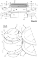
- FIGS 4A 4B and 4C show the screw device 10 in detail in a simplified manner.
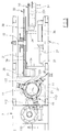
- the screw device 10 comprises two or more parallel worms 11 (in this case three are provided) of vertical axis, rotated with the same speed and direction by a motor 110 via a transmission chain 112 and relative sprockets 113 (shown only in Figure 3).
- Each worm 11 comprises a cylindrical body, with a shaft 16, in the lateral surface of which there is provided a helical groove 12 of square cross-section, opening into the upper end 11' and lower end 11'' of the worm 11.
- the remaining part of the body defines a helical thread 13 projecting radially from the base 14 of the groove.
- the worms 11 are distributed angularly and positioned at the same distance from the axis of the pile 81, in geometrical relationship with the articles 8 such that these rest simultaneously, via their peripheral edge 8' (see Figure 5), on the upper end 11' and then on the thread 13.
- a flat thin element 15 having a sharp radial edge 151 and projecting radially from the shaft 16 in the manner of the thread 13, and also projecting above the point in which the groove 12 opens into the upper end 11'.
- the element 15 separates two adjacent articles by means of its edge 151, its angular position relative to the groove 12 being adjustable on the basis of the thickness of the articles 8.
- the article 8 positioned at the bottom of the pile 81 (indicated by 8a in Figures 4A, 4B, 4C) firstly rests, via its edge, on the upper end 11' of the worms 11 (see Figure 4A), then as these rotate, the edge of the article 8a gradually passes to rest on the upper surface of the groove 12. At the moment in which this passage occurs, the edge 151 of the element 15 becomes inserted between the article 8a and that article 8b immediately above it. As the worms 11 continue to rotate, the article 8b (and hence the entire overlying pile) is supported by the element 15 and is held at rest, whereas the edge of the article 8a slides along the groove 12, to move downwards until it leaves the device 10 and falls freely downwards.
- the device 10 separates and spaces (by a distance equal to the pitch of the groove 12) the individual articles from the vertical pile 81 resting on the upper edge of the worms 11, and makes them descend one at a time in succession.
- the device 10 there are positioned a number of angularly distributed vertical rods 61 arranged in mutual geometrical relationship to define a vertical corridor to contain the pile 81 of articles with a certain degree of play.
- two optical sensor means 17 are provided to sense the passage of the articles 8 as these fall from the device 10, and to feed the relative signal to an electronic device (of known type, not shown in the figures) which counts them.
- the track 20 comprises a number of angularly distributed, mutually parallel rods 21 arranged in a geometrical relationship such as to define a corridor to contain a stack of articles 8 with a certain degree of play.
- the rods 21 are curved to form a substantially circumference-shaped path preferably passing through an angle of 100-150 degrees.
- the rods 21 are connected together and supported by rings 22, each of which is fixed to all the rods 21.
- the rings are open in that region facing the interior of the arc so that between the two rods 21 positioned in this region a longitudinal channel remains open for passage of the radial elements 33a and 33b (described in detail hereinafter).
- a rotary device 30 arranged to accompany the stacks of articles 8 and urge the stacks, one at a time, along the track 20 from the point in which they leave the screw device to the final station 50.
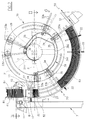
- the rotary device 30 comprises a wheel 31 of horizontal axis positioned to the side of but close to the middle vertical plane through the track 20, which extends substantially as an arc of a circle with its centre substantially coaxial to the wheel 31. This latter is carried by a shaft 32 supported by the general support frame 7 of the apparatus, and is rotated by a motor 310 via a chain transmission 311.
- the wheel 31 rotates a plurality of pairs of radial elements 33a and 33b, each comprising two parallel radial rods 331 joined together at their inner end by a rear piece 34.
- Each radial element 33a, 33b is secured to the wheel 31 by a respective guide piece 35 which is fixed to the wheel 31 and has two radial through holes through which the rods 331 slide as an exact fit.
- the elements 33a and 33b can be moved radially to the wheel 31, between an extracted position in which they are relatively far from the centre of the wheel 31 to interfere with the path of the cylinder-piston units 8 positioned on the continuous track, and a retracted position in which they are relatively close to the centre of the wheel and do not interfere with the articles 8.
- the guide pieces 35 are fixed to the front face of the wheel 31 and project axially forwards from it such that the middle vertical plane in which the elements 33a, 33b move is substantially coplanar with the middle vertical plane through the length of the track 20.
- Means for radially displacing the elements 33a, 33b are also provided, to move the radial elements 33a, 33b into and maintain them in their extracted position and their retracted position successively, in combination with the rotation of the wheel 31.
- These means comprise a pneumatic cylinder-piston unit 36 supported by the frame 7 in a fixed position to the side of the central region of the wheel 31, such as not to interfere with the path of the elements 33a, 33b rotated by the wheel 31.
- the horizontal projection of the axis of the cylinder-piston unit 36 passes substantially through the centre of the wheel 31.
- the rod of the cylinder-piston unit 36 carries at its end a body 37 projecting sideways towards the wheel 31 and into the path defined by the rear pieces 34.
- the body 37 When the rod of the cylinder-piston unit 36 is in a retracted position, the body 37 is close to the axis of the wheel 31 (as shown by dashed and dotted lines in Figure 3) and does not interfere with the path of the elements 33a, 33b, whereas when the rod is extended, the body 37 intercepts that piece 34 lying in the same trajectory to urge the relative radial element 33a, 33b into its extracted position (as shown by full lines in Figure 3).
- a fixed vertical disc 38 fixed to the frame 7 in a position to the inside of the path of the guide pieces 35 so as not to interfere with them.
- a track 39 formed from two forward-projecting concentric walls 39' and 39'', between which the rear pieces 34 slide in a guided manner.
- the radial elements are divided into a number of pairs (three in the embodiment shown in the figures), each comprising an upstream element 33a and a downstream element 33b.
- the elements 33a, 33b of each pair form between them an angle slightly greater than the angle of the circumferential arc defined by a stack of articles 8 of predetermined number lying on the track 20.
- the cylinder-piston unit 36 operates to move the radial elements 33a, 33b into their extracted position when these reach a predetermined angular position in which they lie a short distance from the exit of the screw device.
- the cylinder-piston unit 36 has its axis in a horizontal plane P (in which the axis of the wheel 31 also lies) positioned a short distance below the exit of the device 10, to extract the radial elements 33a, 33b when these lie in the plane P.
- the track 39 commences in the plane P, at the point in which the rear piece 34 lies when the element 33a, 33b is in its extracted position, and continues in the direction of advancement of the articles, to remain at a constant distance from the axis of the wheel 31 and hence maintain the elements 33a, 33b in their extracted position.
- the track 39 gradually reduces its distance from the wheel 31, to return the elements 33a, 33b to their retracted position.
- the apparatus also comprises an automatic control system, of known type not shown in the figures, connected to the article counting means.
- the articles 8 to be handled by the apparatus of the invention are positioned initially in the vertical corridor defined by the rods 61, to form a pile 81 of indefinite length.
- the apparatus of the invention operates in the form of operating cycles, each comprising a first stage in which the cylinder-piston units 8 leaving the device 10 are counted while they descend, and are stacked within the descending portion of the track 20 by resting against a front radial element 33a.
- the second stage is implemented in which the complete stack is moved forwards through a small angle and a rear radial element 33b is placed against the upstream end of the complete stack.
- a front radial element 33a lies in the horizontal plane P and is urged into its extracted position by the cylinder-piston unit 36, such that its most outer portion intersects the track 20 at a point just below the exit of the articles 8 from the device 10 (as shown by dashed and dotted lines in Figure 2).
- a sensor 18 is provided to inform the automatic control system when the top of the stack 82 has reached a predetermined distance from the exit of the device 10. As soon as this happens, the system produces a (relatively small) angular movement of the wheel 31 to lower the top of the stack.
- the wheel 31 then advances in small angular steps (in an anticlockwise direction), until the stack 82 has attained the predetermined number of articles 8.
- the stack 82 is supported by the track 20 and by the single radial element 33a, which is maintained in its extracted position, guided by the track 39. It is therefore necessary for the stack 82 to occupy not more than the descending portion of the track 20, or that plus only a small part of the rising portion, to enable the articles 8 to accumulate compactly by gravity, one on another.
- the front element 33a has therefore preferably not exceeded or only slightly exceeded the minimum point of the track 20.
- the system commences the short second stage of the cycle, in which while the operation of the device 10 is halted, the wheel 31 is firstly rotated through a small angle such as to bring the rear element 33b into the plane P.
- the cylinder-piston unit 36 is operated to move the element 33b into its extracted position (as shown in Figure 1) in which, because of its angular distance from the element 33a, it lies slightly above the top of the stack 82.
- the stack of articles which is now composed of the predetermined number of articles 8 (stack complete, now indicated by 83), is enclosed by the pair of elements 33a and 33b.
- the system rotates the wheel 31 to move the front element 33a of the next pair of elements 33a, 33b into the plane P, the device 10 then again operating to recommence the aforedescribed cycle.
- the complete stack 83 is enclosed at its two ends by a pair of elements 33a and 33b and can hence rise along the ascending portion of the track 20, while remaining compact. This happens while the articles 8 continue to gradually descend from the device 10 and the wheel 31 advances in small steps to produce a forming pile 82 resting on the following front element 33a.
- the complete stack 83 is urged up the ascending portion of the track 20 by the rear element 33b until it enters the station 50, to rest on an upwardly inclined straight chute 51.
- the track 20 terminates after the commencement of the station 50, and the stack 83 lying on the chute 51 can be gripped by known means which transfer it to the next operating station.
- the stack 83 can be conveniently manipulated by a transfer device such as that described in Italian patent No. 1260119 of the present applicant, comprising two longitudinal elements (not shown in the figures) acting as a clamp to grip the stack 83 lying on the chute 51 along its lateral sides, and moving along a fixed guide 52, the initial portion of which lies below the chute 51.
- a transfer device such as that described in Italian patent No. 1260119 of the present applicant, comprising two longitudinal elements (not shown in the figures) acting as a clamp to grip the stack 83 lying on the chute 51 along its lateral sides, and moving along a fixed guide 52, the initial portion of which lies below the chute 51.
- the track 39 gradually returns it to its retracted position.
- the elements 33a and 33b remain in their extracted state, partly compelled by the track 39 and partly by their own weight, until they reach the position defined by the plane P.
- This invention enables stacks to be obtained composed of any precise number of articles, and presented on a station in a position comfortable for manipulation by a subsequent machine.
Landscapes
- Engineering & Computer Science (AREA)
- Mechanical Engineering (AREA)
- Closures For Containers (AREA)
- Packaging For Recording Disks (AREA)
- Chemically Coating (AREA)
- Specific Conveyance Elements (AREA)
Abstract
Description
Claims (8)
- An apparatus for forming stacks of discoidal articles of predetermined number, in particular of metal lids for cans and the like, characterised by comprising:a screw device (10) arranged to deliver the articles one at a time, in a manner spaced from the others, after withdrawing them from a vertical pile resting on it;means for counting the articles delivered by the screw device (10);a continuous track (20) along which the articles slide in a stacked arrangement and which commences downstream of the screw device (10) to lead the stacks containing a predetermined number of articles to a final station (50) in which the stacks are positioned horizontally or inclined;a rotary device (30) which accompanies the stacks of articles of predetermined number and urges them one at a time along said track (20) from the point in which they leave the screw device (10) to the final station (50).
- An apparatus as claimed in claim 1, characterised in that the screw device comprises two or more identically rotated worms (11) of vertical axis, on the thread of which there rests the peripheral edge of the articles and which are arranged to individually separate the articles from the vertical pile 81 which rests on the worms (11), and to cause them to descend by rotating the worms (11).
- An apparatus as claimed in claim 1, characterised in that said continuous track (20) on which the stacked articles slide commences vertically from its upstream end to then, after passing through an angle of at least 90 degrees, lead the stack of articles to a final station (50) in which the stacks are positioned horizontally or inclined.
- An apparatus as claimed in claim 4, characterised in that the rotary device (30) comprises:a wheel (31) of horizontal axis positioned to the side of and coplanar with the continuous track (20), the continuous track (20) having a path substantially in the form of a circumferential arc with its centre substantially coaxial with the wheel (31);a plurality of pairs of radial elements (33a, 33b) which are rotated by the wheel (31) and can be moved radially to the wheel (31) between an extracted position in which they interfere with the path of the articles on the continuous track (20), and a retracted position in which they do not interfere with said articles;means for radially displacing the radial elements (33a, 33b), to move the radial elements into and then maintain them in an extracted position and in a retracted position successively, in combination with the rotation of the wheel (31).
- An apparatus as claimed in claim 3, characterised in that the radial elements 33a, 33b of each pair form between them an angle slightly greater than the angle of the circumferential arc defined by a stack of articles of predetermined number lying on the track (20), said means (36, 39) for radially displacing the radial elements (33a, 33b) operating by moving these latter into their extracted position when they lie in a predetermined angular position at a short distance from the exit of the screw device (10), and returning them to their retracted position when the radial elements (33a, 33b) have passed beyond the commencement of the final station (50).
- An apparatus as claimed in claim 3, characterised by comprising a control system, connected to the article counting means in order to determine cyclic operation, each cycle comprising:a first stage in which the cylinder-piston units (8) leaving the device (10) are counted while they descend, and are stacked within the descending portion of the track (20) by resting against a front radial element (33a) until the stack attains the predetermined number of articles (8);a second stage in which the complete stack is moved forwards through a small angle and a rear radial element (33b) is placed against the upstream end of the complete stack;during the first stage of the next cycle, while a stack resting against the next front radial element (33a) is being formed, the previously formed complete pile is urged by the relative rear radial element (33b) along the ascending portion of the track (20), as far as the final station (50).
- An apparatus as claimed in claim 6, characterised in that at the commencement of the operating cycle, a front radial element (33a) lies in the horizontal plane P and is urged into its extracted position by the cylinder-piston unit (36), such that its most outer portion intersects the track (20) at a point just below the exit of the device (10), after which as the articles (8) enter the track (20), where they accumulate to form a stack (82), the device 30 is rotated in the same direction, to lower the front element (33a) such that the top of the stack (82) under formation is always a short distance from the exit of the device (10).
- An apparatus as claimed in claim 6, characterised in that during the second stage of the cycle, while the operation of the screw device (10) is halted,the wheel (31) is firstly rotated through a small angle such as to bring the rear element (33b) into the plane P;immediately afterwards, the cylinder-piston unit (36) is operated to move the element (33b) into its extracted position in which it lies slightly above the top of the stack (82);the wheel (31) is then rotated to move the front element (33a) of the next pair of elements (33a, 33b) into the plane P.
Applications Claiming Priority (2)
| Application Number | Priority Date | Filing Date | Title |
|---|---|---|---|
| ITRE990052 | 1999-04-29 | ||
| IT1999RE000052A IT1309756B1 (en) | 1999-04-29 | 1999-04-29 | EQUIPMENT FOR FORMING STACKS OF DISCOID OBJECTS IN PRE-FIXED NUMBER, IN PARTICULAR FOR METAL LIDS OF JARS |
Publications (3)
| Publication Number | Publication Date |
|---|---|
| EP1048596A2 true EP1048596A2 (en) | 2000-11-02 |
| EP1048596A3 EP1048596A3 (en) | 2002-06-12 |
| EP1048596B1 EP1048596B1 (en) | 2003-12-10 |
Family
ID=11399438
Family Applications (1)
| Application Number | Title | Priority Date | Filing Date |
|---|---|---|---|
| EP00201330A Expired - Lifetime EP1048596B1 (en) | 1999-04-29 | 2000-04-13 | Apparatus for forming stacks of discoidal articles of predetermined number, in particular metal lids for cans and the like |
Country Status (6)
| Country | Link |
|---|---|
| US (1) | US6443689B1 (en) |
| EP (1) | EP1048596B1 (en) |
| AT (1) | ATE256062T1 (en) |
| DE (1) | DE60007021T2 (en) |
| ES (1) | ES2209758T3 (en) |
| IT (1) | IT1309756B1 (en) |
Cited By (9)
| Publication number | Priority date | Publication date | Assignee | Title |
|---|---|---|---|---|
| EP1375397A1 (en) * | 2002-06-28 | 2004-01-02 | Bouw & Handelmij. Nijkerk B.V. | Apparatus and method for manipulating plate-shaped construction elements |
| ITBO20090777A1 (en) * | 2009-12-02 | 2011-06-03 | Sts Internat S R L | CIRCULAR ROTARY MEMBER TO RECOGNIZE THE PLASTIC CONTAINER EDGES INSERT THE ONE INSIDE THE OTHER AND TO ALLOW THE ADVANCEMENT OF THE SAME CONTAINERS ONE BY TIME AND TO GROUP THE ROTATING CIRCULAR MEMBER |
| EP1841677A4 (en) * | 2004-12-23 | 2012-06-27 | Snaptron Inc | PLACEMENT SYSTEM FOR SWITCH CONTACTS |
| CN103274214A (en) * | 2013-06-20 | 2013-09-04 | 舟山市普陀博达机械制造有限公司 | Multi-workstation high-speed cover distributing device |
| WO2016071075A1 (en) * | 2014-11-03 | 2016-05-12 | Khs Gmbh | Transport star for guiding containers |
| CN105966928A (en) * | 2015-03-10 | 2016-09-28 | 红牛有限责任公司 | Device for separating can lids |
| WO2017060030A1 (en) * | 2015-10-08 | 2017-04-13 | Schuler Pressen Gmbh | Feed device for feeding round blank rings made from plastic and arrangement for transporting round blank rings of this type |
| CN106697417A (en) * | 2017-02-23 | 2017-05-24 | 赖新庭 | Automatic cup conveying and separating discharging device for stacked cups |
| US12187554B2 (en) | 2020-11-04 | 2025-01-07 | Js Stål Aps | Destacker unit and system for destacking of objects |
Families Citing this family (7)
| Publication number | Priority date | Publication date | Assignee | Title |
|---|---|---|---|---|
| DE60208879T2 (en) * | 2001-03-28 | 2006-11-02 | Showa Denko K.K. | PLATE MEMBER STACKING DEVICE, METHOD FOR STACKING PLATE MEMBERS AND STACKED PLATE MEMBERS |
| FR2859714B1 (en) * | 2003-09-12 | 2005-11-11 | Aries Packaging | METHOD FOR FORMING AND SPACING SUCCESSIVE LOTS OF ARTICLES |
| US7726932B2 (en) * | 2004-05-28 | 2010-06-01 | Axium, Inc. | Method and tool for the separation of a pile of recipients |
| CN103340116A (en) * | 2013-07-20 | 2013-10-09 | 常继生 | Light wide-opening container collection device |
| US10556758B1 (en) * | 2017-03-08 | 2020-02-11 | Maxco Supply, Inc. | Denester and method of denesting a stack of containers |
| CN108482724B (en) * | 2018-03-27 | 2021-05-28 | 山东正阳科技有限公司 | cover feeding mechanism |
| CN111137484A (en) * | 2020-01-20 | 2020-05-12 | 杭州加一包装技术有限责任公司 | Distributing device and packaging equipment for bottom cover |
Family Cites Families (10)
| Publication number | Priority date | Publication date | Assignee | Title |
|---|---|---|---|---|
| GB528265A (en) * | 1938-05-05 | 1940-10-25 | Ball Brothers Co | Improvements in apparatus for transferring articles from a machine to a conveyor or another machine |
| FR1381294A (en) * | 1963-07-27 | 1964-12-14 | Automatic feeder for cheese box chips | |
| DE1923176A1 (en) * | 1969-05-07 | 1970-11-19 | H Christian Radbruch Fa | Stacking device |
| US3988875A (en) * | 1975-11-05 | 1976-11-02 | J. W. Fay & Son, Inc. | Apparatus for producing and packaging food chips |
| DE3865168D1 (en) * | 1987-10-15 | 1991-10-31 | Sig Schweiz Industrieges | METHOD AND DEVICE FOR FORMING AND TRANSPORTING GROUPS OF FOOD DISC LAYING ON THE SIDE, IN PARTICULAR BISCUITS. |
| IT1223884B (en) * | 1988-11-03 | 1990-09-29 | Cavanna Spa | DEVICE FOR THE TRANSFER OF STACKS OF PRODUCTS IN PACKAGING AND EQUIPMENT INCLUDING SUCH A DEVICE |
| US5163073A (en) * | 1991-03-18 | 1992-11-10 | Ball Corporation | Can end counting system |
| US5476362A (en) * | 1993-02-16 | 1995-12-19 | Preferred Machining Corp. | Can lid downstacker mechanism |
| US5494399A (en) * | 1993-02-19 | 1996-02-27 | Rapsco, Inc. | Can end distributor apparatus |
| US5931341A (en) * | 1997-11-14 | 1999-08-03 | Wild Horse Industrial Corporation | Adjustable high speed lid dropper |
-
1999
- 1999-04-29 IT IT1999RE000052A patent/IT1309756B1/en active
-
2000
- 2000-04-13 DE DE60007021T patent/DE60007021T2/en not_active Expired - Fee Related
- 2000-04-13 ES ES00201330T patent/ES2209758T3/en not_active Expired - Lifetime
- 2000-04-13 AT AT00201330T patent/ATE256062T1/en not_active IP Right Cessation
- 2000-04-13 EP EP00201330A patent/EP1048596B1/en not_active Expired - Lifetime
- 2000-04-28 US US09/559,968 patent/US6443689B1/en not_active Expired - Fee Related
Cited By (16)
| Publication number | Priority date | Publication date | Assignee | Title |
|---|---|---|---|---|
| EP1375397A1 (en) * | 2002-06-28 | 2004-01-02 | Bouw & Handelmij. Nijkerk B.V. | Apparatus and method for manipulating plate-shaped construction elements |
| EP1841677A4 (en) * | 2004-12-23 | 2012-06-27 | Snaptron Inc | PLACEMENT SYSTEM FOR SWITCH CONTACTS |
| US8424717B2 (en) | 2004-12-23 | 2013-04-23 | Snaptron, Inc. | Efficient delivery and placement systems for switch contacts |
| ITBO20090777A1 (en) * | 2009-12-02 | 2011-06-03 | Sts Internat S R L | CIRCULAR ROTARY MEMBER TO RECOGNIZE THE PLASTIC CONTAINER EDGES INSERT THE ONE INSIDE THE OTHER AND TO ALLOW THE ADVANCEMENT OF THE SAME CONTAINERS ONE BY TIME AND TO GROUP THE ROTATING CIRCULAR MEMBER |
| EP2330063A1 (en) * | 2009-12-02 | 2011-06-08 | STS International S.r.l | Helical rotating member for grouping or destacking containers |
| CN103274214A (en) * | 2013-06-20 | 2013-09-04 | 舟山市普陀博达机械制造有限公司 | Multi-workstation high-speed cover distributing device |
| CN103274214B (en) * | 2013-06-20 | 2016-04-20 | 舟山市普陀博达机械制造有限公司 | Multistation high-speed divides lid arrangement |
| WO2016071075A1 (en) * | 2014-11-03 | 2016-05-12 | Khs Gmbh | Transport star for guiding containers |
| CN105966928A (en) * | 2015-03-10 | 2016-09-28 | 红牛有限责任公司 | Device for separating can lids |
| WO2017060030A1 (en) * | 2015-10-08 | 2017-04-13 | Schuler Pressen Gmbh | Feed device for feeding round blank rings made from plastic and arrangement for transporting round blank rings of this type |
| CN108290695A (en) * | 2015-10-08 | 2018-07-17 | 许勒压力机有限责任公司 | Feedway for supplying the circular blank ring being made of plastics and the arrangement for transporting such circular blank ring |
| US10392198B2 (en) | 2015-10-08 | 2019-08-27 | Schuler Pressen Gmbh | Feed device for feeding round blank rings made from plastic and arrangement for transporting of such round blank rings |
| DE102016204207B4 (en) * | 2015-10-08 | 2020-03-19 | Schuler Pressen Gmbh | Feeding device for round blanks |
| DE102016204208B4 (en) * | 2015-10-08 | 2020-03-19 | Schuler Pressen Gmbh | Feeding device for feeding round plastic rings and arrangement for transporting such round rings |
| CN106697417A (en) * | 2017-02-23 | 2017-05-24 | 赖新庭 | Automatic cup conveying and separating discharging device for stacked cups |
| US12187554B2 (en) | 2020-11-04 | 2025-01-07 | Js Stål Aps | Destacker unit and system for destacking of objects |
Also Published As
| Publication number | Publication date |
|---|---|
| EP1048596B1 (en) | 2003-12-10 |
| US6443689B1 (en) | 2002-09-03 |
| EP1048596A3 (en) | 2002-06-12 |
| ITRE990052A1 (en) | 2000-10-29 |
| IT1309756B1 (en) | 2002-01-30 |
| DE60007021T2 (en) | 2004-06-03 |
| ATE256062T1 (en) | 2003-12-15 |
| ITRE990052A0 (en) | 1999-04-29 |
| DE60007021D1 (en) | 2004-01-22 |
| ES2209758T3 (en) | 2004-07-01 |
Similar Documents
| Publication | Publication Date | Title |
|---|---|---|
| EP1048596B1 (en) | Apparatus for forming stacks of discoidal articles of predetermined number, in particular metal lids for cans and the like | |
| US4677283A (en) | Device for counting and loading small items into containers | |
| US7080969B2 (en) | Method and apparatus for stacking discrete planar objects | |
| JP2927959B2 (en) | Rotary stacking device | |
| EP1565395B1 (en) | Apparatus and method for stacking and separating sheets discharged from a starwheel assembly | |
| CN100471773C (en) | Apparatus for righting and aligning articles using a drop chute comprising a plurality of compartments | |
| CN1200807A (en) | Apparatus for weighing small products such as capsules | |
| JPH01162670A (en) | Sorting stacker for stock | |
| EP1421021A2 (en) | Apparatus and method for stacking sheets discharged from a starwheel assembly | |
| SE501944C2 (en) | Method and apparatus for handling sheets provided with information in a laser printer | |
| CN107108131B (en) | Apparatus and method for reliably supplying compliant closure elements | |
| US6267550B1 (en) | Container nesting and counting apparatus | |
| US6585477B1 (en) | Counter-stacker for flat food products | |
| EP0302837B1 (en) | Device for selecting a predetermined number of containers partially inserted within one another, thereby forming a package of the same containers | |
| JPH0329648B2 (en) | ||
| JPH0194495A (en) | Selector for coin processing apparatus | |
| US4861312A (en) | Coin handling apparatus | |
| CA2572049C (en) | Apparatus and method for positioning articles, comprising multiple unloading operations per cycle | |
| WO2022214933A1 (en) | In-line machine for filling and capping containers | |
| US5647589A (en) | Fully automatic device for removal of spot samples | |
| US4785928A (en) | Feeding rod-like articles | |
| EP0085646B1 (en) | Apparatus for counting and collecting paperboards | |
| US4844439A (en) | Receiving device in a sheet conveyor for occasional collection of sheets before continued conveyance | |
| EP0580578B1 (en) | Machine for stacking cup-shaped containers | |
| CN104220136A (en) | Sorting device for sorting playing cards |
Legal Events
| Date | Code | Title | Description |
|---|---|---|---|
| PUAI | Public reference made under article 153(3) epc to a published international application that has entered the european phase |
Free format text: ORIGINAL CODE: 0009012 |
|
| AK | Designated contracting states |
Kind code of ref document: A2 Designated state(s): AT BE CH CY DE DK ES FI FR GB GR IE IT LI LU MC NL PT SE |
|
| AX | Request for extension of the european patent |
Free format text: AL;LT;LV;MK;RO;SI |
|
| PUAL | Search report despatched |
Free format text: ORIGINAL CODE: 0009013 |
|
| AK | Designated contracting states |
Kind code of ref document: A3 Designated state(s): AT BE CH CY DE DK ES FI FR GB GR IE IT LI LU MC NL PT SE |
|
| AX | Request for extension of the european patent |
Free format text: AL;LT;LV;MK;RO;SI |
|
| 17P | Request for examination filed |
Effective date: 20021122 |
|
| AKX | Designation fees paid |
Designated state(s): AT BE CH CY DE DK ES FI FR GB GR IE IT LI LU MC NL PT SE |
|
| GRAH | Despatch of communication of intention to grant a patent |
Free format text: ORIGINAL CODE: EPIDOS IGRA |
|
| GRAS | Grant fee paid |
Free format text: ORIGINAL CODE: EPIDOSNIGR3 |
|
| GRAA | (expected) grant |
Free format text: ORIGINAL CODE: 0009210 |
|
| RIN1 | Information on inventor provided before grant (corrected) |
Inventor name: REGGIANI, GIUSEPPE,C/O CLEVERTECH S.R.L. |
|
| AK | Designated contracting states |
Kind code of ref document: B1 Designated state(s): AT BE CH CY DE DK ES FI FR GB GR IE IT LI LU MC NL PT SE |
|
| PG25 | Lapsed in a contracting state [announced via postgrant information from national office to epo] |
Ref country code: FI Free format text: LAPSE BECAUSE OF FAILURE TO SUBMIT A TRANSLATION OF THE DESCRIPTION OR TO PAY THE FEE WITHIN THE PRESCRIBED TIME-LIMIT Effective date: 20031210 Ref country code: LI Free format text: LAPSE BECAUSE OF FAILURE TO SUBMIT A TRANSLATION OF THE DESCRIPTION OR TO PAY THE FEE WITHIN THE PRESCRIBED TIME-LIMIT Effective date: 20031210 Ref country code: CY Free format text: LAPSE BECAUSE OF FAILURE TO SUBMIT A TRANSLATION OF THE DESCRIPTION OR TO PAY THE FEE WITHIN THE PRESCRIBED TIME-LIMIT Effective date: 20031210 Ref country code: CH Free format text: LAPSE BECAUSE OF FAILURE TO SUBMIT A TRANSLATION OF THE DESCRIPTION OR TO PAY THE FEE WITHIN THE PRESCRIBED TIME-LIMIT Effective date: 20031210 |
|
| REG | Reference to a national code |
Ref country code: GB Ref legal event code: FG4D |
|
| REG | Reference to a national code |
Ref country code: CH Ref legal event code: EP |
|
| REG | Reference to a national code |
Ref country code: IE Ref legal event code: FG4D |
|
| REF | Corresponds to: |
Ref document number: 60007021 Country of ref document: DE Date of ref document: 20040122 Kind code of ref document: P |
|
| PG25 | Lapsed in a contracting state [announced via postgrant information from national office to epo] |
Ref country code: GR Free format text: LAPSE BECAUSE OF FAILURE TO SUBMIT A TRANSLATION OF THE DESCRIPTION OR TO PAY THE FEE WITHIN THE PRESCRIBED TIME-LIMIT Effective date: 20040310 Ref country code: DK Free format text: LAPSE BECAUSE OF FAILURE TO SUBMIT A TRANSLATION OF THE DESCRIPTION OR TO PAY THE FEE WITHIN THE PRESCRIBED TIME-LIMIT Effective date: 20040310 Ref country code: SE Free format text: LAPSE BECAUSE OF FAILURE TO SUBMIT A TRANSLATION OF THE DESCRIPTION OR TO PAY THE FEE WITHIN THE PRESCRIBED TIME-LIMIT Effective date: 20040310 |
|
| PG25 | Lapsed in a contracting state [announced via postgrant information from national office to epo] |
Ref country code: IE Free format text: LAPSE BECAUSE OF NON-PAYMENT OF DUE FEES Effective date: 20040413 Ref country code: LU Free format text: LAPSE BECAUSE OF NON-PAYMENT OF DUE FEES Effective date: 20040413 |
|
| PG25 | Lapsed in a contracting state [announced via postgrant information from national office to epo] |
Ref country code: MC Free format text: LAPSE BECAUSE OF NON-PAYMENT OF DUE FEES Effective date: 20040430 |
|
| REG | Reference to a national code |
Ref country code: CH Ref legal event code: PL |
|
| REG | Reference to a national code |
Ref country code: ES Ref legal event code: FG2A Ref document number: 2209758 Country of ref document: ES Kind code of ref document: T3 |
|
| ET | Fr: translation filed | ||
| PLBE | No opposition filed within time limit |
Free format text: ORIGINAL CODE: 0009261 |
|
| STAA | Information on the status of an ep patent application or granted ep patent |
Free format text: STATUS: NO OPPOSITION FILED WITHIN TIME LIMIT |
|
| 26N | No opposition filed |
Effective date: 20040913 |
|
| REG | Reference to a national code |
Ref country code: IE Ref legal event code: MM4A |
|
| PG25 | Lapsed in a contracting state [announced via postgrant information from national office to epo] |
Ref country code: PT Free format text: LAPSE BECAUSE OF NON-PAYMENT OF DUE FEES Effective date: 20040510 |
|
| PGFP | Annual fee paid to national office [announced via postgrant information from national office to epo] |
Ref country code: FR Payment date: 20090724 Year of fee payment: 10 Ref country code: ES Payment date: 20090729 Year of fee payment: 10 |
|
| PGFP | Annual fee paid to national office [announced via postgrant information from national office to epo] |
Ref country code: DE Payment date: 20090723 Year of fee payment: 10 Ref country code: GB Payment date: 20090727 Year of fee payment: 10 Ref country code: AT Payment date: 20090727 Year of fee payment: 10 Ref country code: NL Payment date: 20090724 Year of fee payment: 10 |
|
| PGFP | Annual fee paid to national office [announced via postgrant information from national office to epo] |
Ref country code: BE Payment date: 20090817 Year of fee payment: 10 |
|
| PGFP | Annual fee paid to national office [announced via postgrant information from national office to epo] |
Ref country code: IT Payment date: 20090728 Year of fee payment: 10 |
|
| BERE | Be: lapsed |
Owner name: *CLEVERTECH S.R.L. Effective date: 20100430 |
|
| REG | Reference to a national code |
Ref country code: NL Ref legal event code: V1 Effective date: 20101101 |
|
| GBPC | Gb: european patent ceased through non-payment of renewal fee |
Effective date: 20100413 |
|
| REG | Reference to a national code |
Ref country code: FR Ref legal event code: ST Effective date: 20101230 |
|
| PG25 | Lapsed in a contracting state [announced via postgrant information from national office to epo] |
Ref country code: FR Free format text: LAPSE BECAUSE OF NON-PAYMENT OF DUE FEES Effective date: 20100430 Ref country code: NL Free format text: LAPSE BECAUSE OF NON-PAYMENT OF DUE FEES Effective date: 20101101 Ref country code: AT Free format text: LAPSE BECAUSE OF NON-PAYMENT OF DUE FEES Effective date: 20100413 |
|
| PG25 | Lapsed in a contracting state [announced via postgrant information from national office to epo] |
Ref country code: DE Free format text: LAPSE BECAUSE OF NON-PAYMENT OF DUE FEES Effective date: 20101103 |
|
| PG25 | Lapsed in a contracting state [announced via postgrant information from national office to epo] |
Ref country code: IT Free format text: LAPSE BECAUSE OF NON-PAYMENT OF DUE FEES Effective date: 20100413 Ref country code: BE Free format text: LAPSE BECAUSE OF NON-PAYMENT OF DUE FEES Effective date: 20100430 Ref country code: GB Free format text: LAPSE BECAUSE OF NON-PAYMENT OF DUE FEES Effective date: 20100413 |
|
| REG | Reference to a national code |
Ref country code: ES Ref legal event code: FD2A Effective date: 20110715 |
|
| PG25 | Lapsed in a contracting state [announced via postgrant information from national office to epo] |
Ref country code: ES Free format text: LAPSE BECAUSE OF NON-PAYMENT OF DUE FEES Effective date: 20110705 |
|
| PG25 | Lapsed in a contracting state [announced via postgrant information from national office to epo] |
Ref country code: ES Free format text: LAPSE BECAUSE OF NON-PAYMENT OF DUE FEES Effective date: 20100414 |