EP1048609B1 - Getränkekühler - Google Patents
Getränkekühler Download PDFInfo
- Publication number
- EP1048609B1 EP1048609B1 EP00303474A EP00303474A EP1048609B1 EP 1048609 B1 EP1048609 B1 EP 1048609B1 EP 00303474 A EP00303474 A EP 00303474A EP 00303474 A EP00303474 A EP 00303474A EP 1048609 B1 EP1048609 B1 EP 1048609B1
- Authority
- EP
- European Patent Office
- Prior art keywords
- line
- condenser
- heat exchange
- coolant
- trim cooler
- Prior art date
- Legal status (The legal status is an assumption and is not a legal conclusion. Google has not performed a legal analysis and makes no representation as to the accuracy of the status listed.)
- Expired - Lifetime
Links
- 235000013361 beverage Nutrition 0.000 title description 2
- 239000002826 coolant Substances 0.000 claims abstract description 70
- 238000001816 cooling Methods 0.000 claims abstract description 16
- 239000007788 liquid Substances 0.000 claims abstract description 15
- XLYOFNOQVPJJNP-UHFFFAOYSA-N water Substances O XLYOFNOQVPJJNP-UHFFFAOYSA-N 0.000 claims description 16
- 238000001704 evaporation Methods 0.000 description 10
- 230000008020 evaporation Effects 0.000 description 10
- 239000000463 material Substances 0.000 description 5
- 238000005057 refrigeration Methods 0.000 description 4
- 239000007787 solid Substances 0.000 description 4
- 239000000498 cooling water Substances 0.000 description 3
- RYGMFSIKBFXOCR-UHFFFAOYSA-N Copper Chemical compound [Cu] RYGMFSIKBFXOCR-UHFFFAOYSA-N 0.000 description 2
- LYCAIKOWRPUZTN-UHFFFAOYSA-N Ethylene glycol Chemical compound OCCO LYCAIKOWRPUZTN-UHFFFAOYSA-N 0.000 description 2
- 229910052802 copper Inorganic materials 0.000 description 2
- 239000010949 copper Substances 0.000 description 2
- 229910052751 metal Inorganic materials 0.000 description 2
- 239000002184 metal Substances 0.000 description 2
- 229910001220 stainless steel Inorganic materials 0.000 description 2
- 239000010935 stainless steel Substances 0.000 description 2
- 239000004411 aluminium Substances 0.000 description 1
- 229910052782 aluminium Inorganic materials 0.000 description 1
- XAGFODPZIPBFFR-UHFFFAOYSA-N aluminium Chemical compound [Al] XAGFODPZIPBFFR-UHFFFAOYSA-N 0.000 description 1
- 230000015572 biosynthetic process Effects 0.000 description 1
- WGCNASOHLSPBMP-UHFFFAOYSA-N hydroxyacetaldehyde Natural products OCC=O WGCNASOHLSPBMP-UHFFFAOYSA-N 0.000 description 1
- 235000015095 lager Nutrition 0.000 description 1
- 238000000034 method Methods 0.000 description 1
- 239000000203 mixture Substances 0.000 description 1
- 239000003507 refrigerant Substances 0.000 description 1
- 235000014214 soft drink Nutrition 0.000 description 1
- 239000002470 thermal conductor Substances 0.000 description 1
- 238000010792 warming Methods 0.000 description 1
Images




Classifications
-
- B—PERFORMING OPERATIONS; TRANSPORTING
- B67—OPENING, CLOSING OR CLEANING BOTTLES, JARS OR SIMILAR CONTAINERS; LIQUID HANDLING
- B67D—DISPENSING, DELIVERING OR TRANSFERRING LIQUIDS, NOT OTHERWISE PROVIDED FOR
- B67D1/00—Apparatus or devices for dispensing beverages on draught
- B67D1/08—Details
- B67D1/0857—Cooling arrangements
- B67D1/0858—Cooling arrangements using compression systems
-
- F—MECHANICAL ENGINEERING; LIGHTING; HEATING; WEAPONS; BLASTING
- F25—REFRIGERATION OR COOLING; COMBINED HEATING AND REFRIGERATION SYSTEMS; HEAT PUMP SYSTEMS; MANUFACTURE OR STORAGE OF ICE; LIQUEFACTION SOLIDIFICATION OF GASES
- F25B—REFRIGERATION MACHINES, PLANTS OR SYSTEMS; COMBINED HEATING AND REFRIGERATION SYSTEMS; HEAT PUMP SYSTEMS
- F25B29/00—Combined heating and refrigeration systems, e.g. operating alternately or simultaneously
- F25B29/003—Combined heating and refrigeration systems, e.g. operating alternately or simultaneously of the compression type system
Definitions
- the present invention relates to a trim cooler for cooling a drink in a drinks line prior to serving.
- trim cooler close to the dispenser and in thermal contact with the drinks line (typically under the bar).
- the trim cooler receives the cooled dink from the drinks line at a temperature of the order five degrees centigrade and cools it by a further three to four centigrade.
- trim coolers are air cooled and include fans which draw air across the condenser of the trim cooler refrigeration unit. Air cooling is relatively inefficient and large fans are required. Such fans considerably increase the size of the trim cooler unit, use a large amount of power and also generate unwanted heat.
- GB 2253 473A discloses an alternative drink cooling system.
- the drink to be cooled is passed through a product coil in thermal contact with an evaporator of a refrigeration system.
- the refrigeration system has a water cooled condenser cooled by water from a further remotely located cooling system.
- GB 2205 638 A discloses a beverage cooling assembly conforming to the preamble of claim 1.
- the trim cooler of the invention does not require a fan to cool the condenser. It is therefore relatively small and so can be positioned under a bar without any significant loss of storage space. It also does not generate unwanted heat. A large number of such trim coolers can be installed below a bar without any unwanted increase in temperature in the surrounding room.
- the water in the python line can therefore be used twice, once to cool the drink as the drink travels along the drinks line from the cellar to the trim cooler and then again to cool the condenser of the trim cooler.
- This efficient use of cooling water reduces the cost of chilling drinks to the required temperature.
- the python line supplies water of a constant temperature the condenser is always maintained at a fixed temperature.
- the refrigeration unit can be optimised to work with a condenser at this fixed temperature.
- Known air cooled trim coolers must be able to operate when being cooled by air of an unknown and variable air temperature.
- the trim cooler of the invention is typically two to three times more efficient than known air cooled trim coolers.
- the liquid coolant is at a temperature of less than the surrounding room temperature.
- a chilled coolant one can increase the efficiency of the trim cooler so reducing the amount of unwanted heat generated by the cooler during use.
- the liquid coolant is water.
- a portion of the coolant line comprises a heat exchange tank through which the liquid coolant flows in use, a portion of the condenser being located within the heat exchange tank and being in thermal contact with the liquid coolant.
- the trim cooler according to the invention further comprises a heat exchange tank, a portion of the condenser and a portion of the coolant line being located within the heat exchange tank, the condenser portion and coolant line portion being in thermal contact.
- the heat exchange tank comprises a heat exchange medium.
- the heat exchange medium ensures an efficient transfer of heat from the condenser to the coolant line.
- the trim cooler further comprises a pump for circulating the heat exchange medium through the exchange tank. This prevents the formation of localised cold spots on the condenser.
- At least one of a portion of the coolant line and a portion of the condenser comprises a coil within the heat exchange tank. Coils increase the length of coolant line or condenser which can be arranged within the heat exchange tank so ensuring an efficient heat transfer.
- the coolant line coil and the condenser coil can be coaxial.
- FIG 1 Shown in figure 1 is a plan view of a known trim cooler 1.
- the trim cooler comprises a refrigerator 2 which in turn comprises an evaporator 3, a condenser (not shown) and a compressor 4.
- the compressor 4 circulates a cooling medium (typically R134A) between the evaporator 3 and the condenser (not shown), resulting in the cooling of the evaporator 3.
- R134A cooling medium
- the trim cooler 1 comprises an evaporator tank 5 located on a cabinet 6. Arranged within the evaporator tank 5 is the evaporator 3 shaped as a coil 7 through which the chilled cooling medium flows. Also located within the evaporator tank 5 is a drinks coil (not shown) through which drink flows in use. The drinks coil and the evaporator coil 7 are made from materials of high thermal conductivity such as copper or stainless steel. The evaporator tank 5 is filled with a heat exchange medium 8 which ensures a good thermal contact between the drinks coil and the evaporator coil 7.
- drink flows from a drinks barrel, along a drinks line, where it is cooled by an adjacent 'python' line.
- the drink then passes through the drink coil portion of the drinks line located within the evaporator tank 5 and then to a dispenser where it is served.
- the compressor 4 circulates the cooling medium between the evaporator coil 7 and the condenser, so cooling the evaporator.
- the evaporator coil 7 is cooler than the drinks coil heat flows from the drinks coil through the heat exchange medium 8 to the evaporator coil 7. This cools the drink to the required serving temperature whilst simultaneously warming the cooling medium.
- Shown in Figure 2 is a schematic view of a trim cooler 21 according to the invention in thermal contact with a drinks line 22.
- the drinks line 22 is connected between a barrel 23 containing drink at room temperature and a dispenser 24.
- the drinks line 22 is wrapped around a python line 25 which contains chilled water.
- a tap of the dispenser 24 is opened the drink travels from the barrel 23, along the drinks line 22 towards the dispenser 24.
- the drink travels along the drinks line 22 it is cooled by contact with the python line 25.
- the trim cooler 21 Located before the dispenser 24 is the trim cooler 21.
- the trim cooler 21 Located before the dispenser 24 is the trim cooler 21.
- the trim cooler 21 When the drink reaches the trim cooler 21 it is colder than room temperature but is typically 3-4°C warmer than the desired serving temperature. The drink is cooled further to the desired temperature by the trim cooler 21 and finally served.
- the trim cooler 21 As with known trim coolers 1, the trim cooler 21 according to the invention comprises an evaporator 25a, a condenser 26 and a compressor 27.
- the compressor is for circulating a cooling medium 28 between the evaporator 25a and condenser 26 so cooling the evaporator 25a.
- the drinks line 22 is in thermal contact with the evaporator 25a, resulting in the cooling of the drink with the drinks line 22.
- the condenser 26 of the trim cooler 21 is cooled by thermal contact with a coolant line 29.
- the coolant line 29 is connected to a coolant source (not shown) which is adapted to supply a liquid coolant to the coolant line 29.
- the coolant line 29 is connected to the python line 25 so receiving chilled water at a uniform temperature.
- the coolant line 29 is connected to a separate source of liquid coolant (not shown).
- Liquid coolant reduces the temperature of the condenser 26 to an optimum working temperature. Use of liquid coolant in this way removes the need for a fan so considerably reducing the size of the trim cooler 21 and also the amount of heat generated.
- the temperature of the cooling water from the python line 25 remains substantially uniform throughout the day.
- the design of the trim cooler 21 can therefore be optimised to work with the condenser 26 at a fixed known temperature.
- the trim cooler 21 of the invention is typically 2 - 3 times more efficient than trim coolers which work when being cooled by air of a temperature which varies throughout the day.
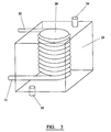
- FIG. 3 Shown in figure 3 is a condenser 26 of an embodiment of a trim cooler 21 according to the invention.
- the condenser 26 is formed as a coil having a high thermal conductivity.
- the cooling medium 28 which has been warmed by its passage through the evaporator 25a enters into the condenser 26 via entrance port 31, flows through the condenser coil 26, and exits at exit port 32 and then returns to the evaporator 25a.
- the condenser is arranged within a heat exchange tank 33. Chilled water from the python line 25 flows into the coolant line 29, enters the heat exchange tank 33 at entrance port 34, flows through the heat exchange tank 33 and then exits at exit port 35.
- the condenser 26 is typically made of a material of high thermal conductivity such as copper stainless steel or aluminium. This ensures efficient cooling of the cooling medium 28 by the chilled water in the heat exchange tank 33 as it passes through the condenser 26.
- FIG 4 Shown in figure 4 is a further embodiment of a condenser 26 of a trim cooler 21 accordingly to the invention.
- the condenser 26 is located within a heat exchange tank 33 and is shaped as a hollow coil.
- the cooling medium 28 enters and exists the condenser coil 26 by entrance port 36 and exit port 37.
- Also located within the heat exchange tank 33 is a portion of the coolant line 29 formed as a hollow coil co-axial with the condenser 26. Cooling water enters the coolant line 29 via water entrance port 38 and exists via water exist port 39. Both coils 26, 29 are immersed in a heat exchange medium ensuring good thermal contact between the condenser coil 26 and the coolant line 29.
- FIG 5 Shown in figure 5 is a further embodiment of a condenser 26 of a trim cooler 21 according to the invention.
- the condenser 26 comprises a hollow tube which extends through a solid block 39a of a high thermal conductivity material.
- the high thermal conductivity material is a metal.
- a coolant line 29 through which chilled water from the python line 25 flows.
- the solid block 39a is a good thermal conductor the condenser 26 and coolant line 29 are in good thermal contact.
- FIG 6 Shown in figure 6 is a further embodiment of a condenser 26 of a trim cooler 21 according to the invention.
- a tubular heat exchange tank 33 Surrounding the condenser 26 is a tubular heat exchange tank 33. Extending through the heat exchange tank 33 parallel to the condenser 26 is a coolant line 29 through which chilled water from the python line 25 flows. The coolant line 29 is in good thermal contact with the condenser 26 ensuring efficient cooling of the cooling medium 28 as it flows through the condenser 26.
- the heat exchange tank 33 is shown as lying in a single plane. In an alternative embodiment it is coiled.
- the evaporator 25a can be used in combination with any of the embodiments of the condenser 26 as previously described.
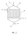
- the evaporator 25a comprises an evaporation tank 40 having an entrance port 41 and an exit port 42.
- the entrance port 41 receives the cooling medium 28 which has previously been chilled by the condenser 26.
- the cooling medium 28 then flows through the evaporation tank 40 to the exit port 42.
- Located within the evaporation tank 40 is a drinks line 22.
- the drinks line 22 is made from a material of high thermal conductivity and is in thermal contact with the cooling medium 28 which flows through the evaporation tank. As drink flows through this portion of the drinks line 22 through the evaporation tank 40 it is chilled by the cooling medium 28 to the required temperature. Simultaneously the cooling medium 28 is warmed by the drink as previously described.
- a further embodiment of an evaporator of a trim cooler according to the invention is arranged as a coil positioned within an evaporation tank.
- the evaporation tank is filled with a heat exchange medium such as a water/glycol mixture or a refrigerant such as R134A.
- a heat exchange medium such as a water/glycol mixture or a refrigerant such as R134A.
- Also located within the evaporation tank is a portion of the drinks line. The heat exchange medium ensures that the drinks line and the evaporator are in good thermal contact. As the drink flows through the drinks line within the evaporation tank it is cooled by the cooling medium in the evaporator.
- the evaporation tank comprises a solid metal block through which the drinks line and the evaporator coil extend.
Landscapes
- Engineering & Computer Science (AREA)
- Physics & Mathematics (AREA)
- Mechanical Engineering (AREA)
- Thermal Sciences (AREA)
- General Engineering & Computer Science (AREA)
- Devices That Are Associated With Refrigeration Equipment (AREA)
- Heat-Exchange Devices With Radiators And Conduit Assemblies (AREA)
- Tea And Coffee (AREA)
- Defrosting Systems (AREA)
- Motor Or Generator Cooling System (AREA)
Claims (9)
- Trimmkühler (1) zum Kühlen eines Getränks in einer Getränkeleitung vor dem Servieren, wobei der Trimmkühler (1)
eine Schlangenleitung (25) in thermischem Kontakt mit der Getränkeleitung (22), wobei die Schlangenleitung (25) so angeschlossen ist, dass sie eine Kühlflüssigkeit konstanter Temperatur zum Kühlen des Getränks zuführt, wobei die Schlangenleitung (22) so an eine Kühlleitung (29) angeschlossen und verbunden ist, dass sie Kühlflüssigkeit zuführt,
eine Wärmetauschervorrichtung in thermischem Kontakt mit der Getränkeleitung zum weiteren Kühlen der Getränkeleitung und in thermischem Kontakt mit der Kühlleitung (29), aufweist,
dadurch gekennzeichnet, dass die Wärmetauschervorrichtung eine Kühlvorrichtung ist mit einem Verdampfer (25a) in thermischem Kontakt mit der Getränkeleitung (22), einem Kondensator (26) in thermischem Kontakt mit der Kühlleitung (29) und einem Kompressor (27) zum Umwälzen eines Kühlmediums zwischen diesen, um den Verdampfer (25a) zu kühlen. - Trimmkühler (1) nach Anspruch 1,
wobei die Kühlflüssigkeit auf einer Temperatur ist, die unter der umgebenden Raumtemperatur ist. - Trimmkühler (1) nach Anspruch 1 oder 2,
wobei die Kühlflüssigkeit Wasser ist. - Trimmkühler nach einem der Ansprüche 1 bis 3,
wobei ein Abschnitt der Kühlleitung (29) einen Wärmetauscherbehälter (33), durch den die Kühlflüssigkeit bei Benutzung strömt, aufweist, wobei ein Abschnitt des Kondensators innerhalb des Wärmetauscherbehälters (33) angordnet und in thermischem Kontakt mit der Kühlflüssigkeit ist. - Trimmkühler nach einem der Ansprüche 1 bis 3,
der ferner einen Wärmetauscherbehälter (33) aufweist, wobei ein Abschnitt des Kondensators (26) und ein Abschnitt der Kühlleitung (29) innerhalb des Wärmetauscherbehälters (33) angeordnet sind und wobei der Kondensatorleitungsabschnitt (26) sowie der Kühleitungsabschnitt (29) in thermischem Kontakt stehen. - Trimmkühler nach Anspruch 5,
wobei der Wärmetauscherbehälter (33) ein Wärmeaustauschmedium aufweist. - Trimmkühler nach Anspruch 6,
ferner mit einer Pumpe zum Umwälzen des Wärmeaustauschmediums durch den Wärmetauscherbehälter (33). - Trimmkühler nach einem der Ansprüche 5 bis 7,
wobei wenigstens einer von einem Abschnitt der Kühlleitung (29) und einem Abschnitt des Kondensators (26) eine Wendel innerhalb des Wärmetauscherbehälters (33) aufweisen - Trimmkühler nach Anspruch 8,
mit einer Kühlleitungswendel und einer Kondensatorwendel innerhalb des Wärmetauscherbehälters (33), wobei die Kühlleitungswendel und die Kondensatorwendel koaxial zueinander sind.
Applications Claiming Priority (2)
| Application Number | Priority Date | Filing Date | Title |
|---|---|---|---|
| GB9909216 | 1999-04-22 | ||
| GBGB9909216.5A GB9909216D0 (en) | 1999-04-22 | 1999-04-22 | A trim cooler |
Publications (2)
| Publication Number | Publication Date |
|---|---|
| EP1048609A1 EP1048609A1 (de) | 2000-11-02 |
| EP1048609B1 true EP1048609B1 (de) | 2003-05-02 |
Family
ID=10852019
Family Applications (1)
| Application Number | Title | Priority Date | Filing Date |
|---|---|---|---|
| EP00303474A Expired - Lifetime EP1048609B1 (de) | 1999-04-22 | 2000-04-25 | Getränkekühler |
Country Status (6)
| Country | Link |
|---|---|
| US (1) | US6357250B1 (de) |
| EP (1) | EP1048609B1 (de) |
| AT (1) | ATE238965T1 (de) |
| DE (1) | DE60002390T2 (de) |
| ES (1) | ES2198254T3 (de) |
| GB (1) | GB9909216D0 (de) |
Cited By (1)
| Publication number | Priority date | Publication date | Assignee | Title |
|---|---|---|---|---|
| WO2024165326A1 (de) * | 2023-02-06 | 2024-08-15 | Steiner Ag Weggis | Verfahren und einrichtung zur durchlaufkühlung von getränken, sowie eine kaffeemaschine |
Families Citing this family (8)
| Publication number | Priority date | Publication date | Assignee | Title |
|---|---|---|---|---|
| DE10224326B4 (de) * | 2002-05-31 | 2007-03-01 | Koszlat, Heinz | Flaschen - Kühler - System |
| EP1731479A1 (de) * | 2005-06-01 | 2006-12-13 | MDS Global Holding Ltd. | Zapfvorrichtung mit Zweistufenkühlung und Karbonisator |
| GB2474741B (en) * | 2009-08-21 | 2012-03-07 | Schroeder Ind Inc | Beverage dispensing apparatus |
| USD693183S1 (en) | 2009-11-30 | 2013-11-12 | Yong C. Lyles | Combined portable chiller and dispensing unit |
| AU2014215515B2 (en) * | 2013-02-06 | 2017-07-13 | H. C. Duke & Son Llc | Chilled food product dispenser and method with adaptive control of refrigeration system |
| CA2958875A1 (en) * | 2014-08-22 | 2016-02-25 | Roasting Plant, Inc. | Beverage chiller and associated systems and methods |
| MX2021014874A (es) | 2019-06-03 | 2022-03-25 | Cooler Heads Care Inc | Conjunto de gorro de enfriamiento y unidad de enfriamiento. |
| WO2026022843A1 (en) * | 2024-07-25 | 2026-01-29 | Dev Jain Ashish | Wateregerator- an adaptable compact continuous water cooling system |
Family Cites Families (14)
| Publication number | Priority date | Publication date | Assignee | Title |
|---|---|---|---|---|
| US3998070A (en) * | 1975-05-28 | 1976-12-21 | Rowe International Inc. | Syrup cooling system for cold drink machine |
| US5079927A (en) * | 1985-11-26 | 1992-01-14 | Rodino A J | Beer cooling apparatus |
| US4730463A (en) * | 1986-05-05 | 1988-03-15 | Stanfill Ted M | Beverage dispenser cooling system |
| US4860923A (en) * | 1986-10-29 | 1989-08-29 | The Coca-Cola Company | Postmix juice dispensing system |
| GB8713319D0 (en) * | 1987-06-06 | 1987-07-08 | Imi Cornelius Uk Ltd | Beverage dispenser |
| US4916910A (en) * | 1988-07-11 | 1990-04-17 | Lancer Corporation | Low profile drink dispenser |
| DE3940878C2 (de) * | 1989-12-11 | 1993-10-14 | Bosch Siemens Hausgeraete | Vorrichtung zum Kühlen von Getränkekomponenten in einem Getränkeautomaten |
| GB2253473A (en) * | 1991-03-05 | 1992-09-09 | Kooltech Limited | Pipeline cooling systems |
| US5280711A (en) * | 1993-02-25 | 1994-01-25 | Imi Cornelius Inc. | Low cost beverage dispensing apparatus |
| US5535600A (en) * | 1994-12-07 | 1996-07-16 | Jet Spray Corp. | Cooling system for a post-mix beverage dispenser |
| US5715700A (en) * | 1995-06-05 | 1998-02-10 | The Coca-Cola Company | Round drink dispenser |
| GB2302403B (en) * | 1995-06-16 | 1999-10-20 | Kooltech Limited | Apparatus for cooling liquids |
| US5873259A (en) * | 1997-08-14 | 1999-02-23 | Utah Milk Technologies, L.C. | System for cooling head of fluid dispensing apparatus |
| US5987900A (en) * | 1998-05-06 | 1999-11-23 | Maximicer, Llc | Method and system for prechilling ambient waters for beverage dispensing machines and ice machines |
-
1999
- 1999-04-22 GB GBGB9909216.5A patent/GB9909216D0/en not_active Ceased
-
2000
- 2000-04-20 US US09/553,727 patent/US6357250B1/en not_active Expired - Fee Related
- 2000-04-25 ES ES00303474T patent/ES2198254T3/es not_active Expired - Lifetime
- 2000-04-25 DE DE60002390T patent/DE60002390T2/de not_active Expired - Lifetime
- 2000-04-25 AT AT00303474T patent/ATE238965T1/de not_active IP Right Cessation
- 2000-04-25 EP EP00303474A patent/EP1048609B1/de not_active Expired - Lifetime
Cited By (1)
| Publication number | Priority date | Publication date | Assignee | Title |
|---|---|---|---|---|
| WO2024165326A1 (de) * | 2023-02-06 | 2024-08-15 | Steiner Ag Weggis | Verfahren und einrichtung zur durchlaufkühlung von getränken, sowie eine kaffeemaschine |
Also Published As
| Publication number | Publication date |
|---|---|
| DE60002390T2 (de) | 2004-04-01 |
| ES2198254T3 (es) | 2004-02-01 |
| US6357250B1 (en) | 2002-03-19 |
| DE60002390D1 (de) | 2003-06-05 |
| GB9909216D0 (en) | 1999-06-16 |
| ATE238965T1 (de) | 2003-05-15 |
| EP1048609A1 (de) | 2000-11-02 |
Similar Documents
| Publication | Publication Date | Title |
|---|---|---|
| KR101312742B1 (ko) | 음료수 냉각장치, 음료수 냉각장치를 포함하는 냉장고, 및 음료수를 냉각하는 방법 | |
| US6490870B1 (en) | Heat transfer apparatus and method | |
| US8011190B2 (en) | Product cooling | |
| EP1048609B1 (de) | Getränkekühler | |
| GB2327748A (en) | Cooling apparatus | |
| US20030037559A1 (en) | Service case | |
| US20090077999A1 (en) | System And Method For Dispensing A Cooled Beverage | |
| WO2011051000A1 (en) | Beverage coolers | |
| US20060137383A1 (en) | Inline booster for beverage dispensing system | |
| CA2482264A1 (en) | Method and apparatus for chilling draught beverages | |
| US5372014A (en) | Modular cooling system for multiple spaces and dispensed beverages | |
| GB2443332A (en) | Apparatus for dispensing beverages with means for forming condensation, frost or ice on one face of a housing | |
| GB2204389A (en) | Drink cooler | |
| US2677255A (en) | Cooling system for beverage storage and dispensing installations | |
| WO2005106366A1 (en) | Beverage dispense system | |
| EP1862427A1 (de) | Getränkeausgabevorrichtung | |
| US2313226A (en) | Dispenser for carbonated beverages | |
| GB2446792A (en) | Beverage dispense system | |
| CA2486630A1 (en) | Method and apparatus for chilling draught beverages in a trunk line | |
| JPH01213194A (ja) | 飲料自動販売システム | |
| GB2440202A (en) | Multi-Compressor Cooling Apparatus with Current Start-up Control and Used for Cooling Beverages | |
| GB2441215A (en) | Beverage dispense | |
| EP2304353A1 (de) | Vorrichtung zum kühlen von getränken | |
| GB2121943A (en) | Heat exchange apparatus | |
| CA2516150A1 (en) | Method and apparatus for increasing chilling capacity of draught beverage dispense systems |
Legal Events
| Date | Code | Title | Description |
|---|---|---|---|
| PUAI | Public reference made under article 153(3) epc to a published international application that has entered the european phase |
Free format text: ORIGINAL CODE: 0009012 |
|
| AK | Designated contracting states |
Kind code of ref document: A1 Designated state(s): AT BE CH CY DE DK ES FI FR GB GR IE IT LI LU MC NL PT SE |
|
| AX | Request for extension of the european patent |
Free format text: AL;LT;LV;MK;RO;SI |
|
| 17P | Request for examination filed |
Effective date: 20010502 |
|
| AKX | Designation fees paid |
Free format text: AT BE CH CY DE DK ES FI FR GB GR IE IT LI LU MC NL PT SE |
|
| 17Q | First examination report despatched |
Effective date: 20010808 |
|
| RAP1 | Party data changed (applicant data changed or rights of an application transferred) |
Owner name: PAXMAN, NEIL ERIC Owner name: HUGHES, DEREK |
|
| RIN1 | Information on inventor provided before grant (corrected) |
Inventor name: PAXMAN, NEIL ERIC |
|
| GRAH | Despatch of communication of intention to grant a patent |
Free format text: ORIGINAL CODE: EPIDOS IGRA |
|
| GRAH | Despatch of communication of intention to grant a patent |
Free format text: ORIGINAL CODE: EPIDOS IGRA |
|
| GRAH | Despatch of communication of intention to grant a patent |
Free format text: ORIGINAL CODE: EPIDOS IGRA |
|
| GRAA | (expected) grant |
Free format text: ORIGINAL CODE: 0009210 |
|
| AK | Designated contracting states |
Designated state(s): AT BE CH CY DE DK ES FI FR GB GR IE IT LI LU MC NL PT SE |
|
| PG25 | Lapsed in a contracting state [announced via postgrant information from national office to epo] |
Ref country code: LI Free format text: LAPSE BECAUSE OF FAILURE TO SUBMIT A TRANSLATION OF THE DESCRIPTION OR TO PAY THE FEE WITHIN THE PRESCRIBED TIME-LIMIT Effective date: 20030502 Ref country code: AT Free format text: LAPSE BECAUSE OF FAILURE TO SUBMIT A TRANSLATION OF THE DESCRIPTION OR TO PAY THE FEE WITHIN THE PRESCRIBED TIME-LIMIT Effective date: 20030502 Ref country code: FI Free format text: LAPSE BECAUSE OF FAILURE TO SUBMIT A TRANSLATION OF THE DESCRIPTION OR TO PAY THE FEE WITHIN THE PRESCRIBED TIME-LIMIT Effective date: 20030502 Ref country code: CY Free format text: LAPSE BECAUSE OF FAILURE TO SUBMIT A TRANSLATION OF THE DESCRIPTION OR TO PAY THE FEE WITHIN THE PRESCRIBED TIME-LIMIT Effective date: 20030502 Ref country code: NL Free format text: LAPSE BECAUSE OF FAILURE TO SUBMIT A TRANSLATION OF THE DESCRIPTION OR TO PAY THE FEE WITHIN THE PRESCRIBED TIME-LIMIT Effective date: 20030502 Ref country code: BE Free format text: LAPSE BECAUSE OF FAILURE TO SUBMIT A TRANSLATION OF THE DESCRIPTION OR TO PAY THE FEE WITHIN THE PRESCRIBED TIME-LIMIT Effective date: 20030502 Ref country code: CH Free format text: LAPSE BECAUSE OF FAILURE TO SUBMIT A TRANSLATION OF THE DESCRIPTION OR TO PAY THE FEE WITHIN THE PRESCRIBED TIME-LIMIT Effective date: 20030502 |
|
| REG | Reference to a national code |
Ref country code: GB Ref legal event code: FG4D |
|
| REG | Reference to a national code |
Ref country code: CH Ref legal event code: EP |
|
| REF | Corresponds to: |
Ref document number: 60002390 Country of ref document: DE Date of ref document: 20030605 Kind code of ref document: P |
|
| REG | Reference to a national code |
Ref country code: IE Ref legal event code: FG4D |
|
| PG25 | Lapsed in a contracting state [announced via postgrant information from national office to epo] |
Ref country code: SE Free format text: LAPSE BECAUSE OF FAILURE TO SUBMIT A TRANSLATION OF THE DESCRIPTION OR TO PAY THE FEE WITHIN THE PRESCRIBED TIME-LIMIT Effective date: 20030802 Ref country code: DK Free format text: LAPSE BECAUSE OF FAILURE TO SUBMIT A TRANSLATION OF THE DESCRIPTION OR TO PAY THE FEE WITHIN THE PRESCRIBED TIME-LIMIT Effective date: 20030802 Ref country code: GR Free format text: LAPSE BECAUSE OF FAILURE TO SUBMIT A TRANSLATION OF THE DESCRIPTION OR TO PAY THE FEE WITHIN THE PRESCRIBED TIME-LIMIT Effective date: 20030802 |
|
| PG25 | Lapsed in a contracting state [announced via postgrant information from national office to epo] |
Ref country code: PT Free format text: LAPSE BECAUSE OF FAILURE TO SUBMIT A TRANSLATION OF THE DESCRIPTION OR TO PAY THE FEE WITHIN THE PRESCRIBED TIME-LIMIT Effective date: 20030804 |
|
| NLV1 | Nl: lapsed or annulled due to failure to fulfill the requirements of art. 29p and 29m of the patents act | ||
| REG | Reference to a national code |
Ref country code: CH Ref legal event code: PL |
|
| REG | Reference to a national code |
Ref country code: ES Ref legal event code: FG2A Ref document number: 2198254 Country of ref document: ES Kind code of ref document: T3 |
|
| PLBE | No opposition filed within time limit |
Free format text: ORIGINAL CODE: 0009261 |
|
| STAA | Information on the status of an ep patent application or granted ep patent |
Free format text: STATUS: NO OPPOSITION FILED WITHIN TIME LIMIT |
|
| ET | Fr: translation filed | ||
| 26N | No opposition filed |
Effective date: 20040203 |
|
| PG25 | Lapsed in a contracting state [announced via postgrant information from national office to epo] |
Ref country code: LU Free format text: LAPSE BECAUSE OF NON-PAYMENT OF DUE FEES Effective date: 20040425 |
|
| PG25 | Lapsed in a contracting state [announced via postgrant information from national office to epo] |
Ref country code: MC Free format text: LAPSE BECAUSE OF NON-PAYMENT OF DUE FEES Effective date: 20040430 |
|
| REG | Reference to a national code |
Ref country code: GB Ref legal event code: 737H |
|
| REG | Reference to a national code |
Ref country code: GB Ref legal event code: 737N |
|
| REG | Reference to a national code |
Ref country code: GB Ref legal event code: 737A Free format text: APPEAL TO PATENTS COURT; APPEAL LODGED |
|
| REG | Reference to a national code |
Ref country code: GB Ref legal event code: S37A |
|
| PGFP | Annual fee paid to national office [announced via postgrant information from national office to epo] |
Ref country code: ES Payment date: 20100427 Year of fee payment: 11 Ref country code: IE Payment date: 20100426 Year of fee payment: 11 Ref country code: FR Payment date: 20100504 Year of fee payment: 11 |
|
| PGFP | Annual fee paid to national office [announced via postgrant information from national office to epo] |
Ref country code: DE Payment date: 20100426 Year of fee payment: 11 |
|
| PG25 | Lapsed in a contracting state [announced via postgrant information from national office to epo] |
Ref country code: IT Free format text: LAPSE BECAUSE OF NON-PAYMENT OF DUE FEES Effective date: 20100425 |
|
| PGFP | Annual fee paid to national office [announced via postgrant information from national office to epo] |
Ref country code: IT Payment date: 20100427 Year of fee payment: 11 |
|
| PGRI | Patent reinstated in contracting state [announced from national office to epo] |
Ref country code: IT Effective date: 20110616 |
|
| PGFP | Annual fee paid to national office [announced via postgrant information from national office to epo] |
Ref country code: GB Payment date: 20110526 Year of fee payment: 12 |
|
| REG | Reference to a national code |
Ref country code: DE Ref legal event code: R119 Ref document number: 60002390 Country of ref document: DE |
|
| REG | Reference to a national code |
Ref country code: DE Ref legal event code: R119 Ref document number: 60002390 Country of ref document: DE |
|
| REG | Reference to a national code |
Ref country code: FR Ref legal event code: ST Effective date: 20111230 |
|
| PG25 | Lapsed in a contracting state [announced via postgrant information from national office to epo] |
Ref country code: FR Free format text: LAPSE BECAUSE OF NON-PAYMENT OF DUE FEES Effective date: 20110502 |
|
| REG | Reference to a national code |
Ref country code: IE Ref legal event code: MM4A |
|
| PGRI | Patent reinstated in contracting state [announced from national office to epo] |
Ref country code: IT Effective date: 20110616 |
|
| PG25 | Lapsed in a contracting state [announced via postgrant information from national office to epo] |
Ref country code: IE Free format text: LAPSE BECAUSE OF NON-PAYMENT OF DUE FEES Effective date: 20110425 |
|
| GBPC | Gb: european patent ceased through non-payment of renewal fee |
Effective date: 20120425 |
|
| PG25 | Lapsed in a contracting state [announced via postgrant information from national office to epo] |
Ref country code: GB Free format text: LAPSE BECAUSE OF NON-PAYMENT OF DUE FEES Effective date: 20120425 |
|
| REG | Reference to a national code |
Ref country code: ES Ref legal event code: FD2A Effective date: 20130605 |
|
| PG25 | Lapsed in a contracting state [announced via postgrant information from national office to epo] |
Ref country code: DE Free format text: LAPSE BECAUSE OF NON-PAYMENT OF DUE FEES Effective date: 20111031 |
|
| PG25 | Lapsed in a contracting state [announced via postgrant information from national office to epo] |
Ref country code: ES Free format text: LAPSE BECAUSE OF NON-PAYMENT OF DUE FEES Effective date: 20110426 |