EP1048795A2 - Connecteurs pour panneaux d'écrans - Google Patents
Connecteurs pour panneaux d'écrans Download PDFInfo
- Publication number
- EP1048795A2 EP1048795A2 EP00303497A EP00303497A EP1048795A2 EP 1048795 A2 EP1048795 A2 EP 1048795A2 EP 00303497 A EP00303497 A EP 00303497A EP 00303497 A EP00303497 A EP 00303497A EP 1048795 A2 EP1048795 A2 EP 1048795A2
- Authority
- EP
- European Patent Office
- Prior art keywords
- connector
- locking
- panel
- link
- channel
- Prior art date
- Legal status (The legal status is an assumption and is not a legal conclusion. Google has not performed a legal analysis and makes no representation as to the accuracy of the status listed.)
- Withdrawn
Links
- 230000015572 biosynthetic process Effects 0.000 claims abstract description 45
- 238000005755 formation reaction Methods 0.000 claims abstract description 45
- 229910000838 Al alloy Inorganic materials 0.000 description 3
- XAGFODPZIPBFFR-UHFFFAOYSA-N aluminium Chemical compound [Al] XAGFODPZIPBFFR-UHFFFAOYSA-N 0.000 description 3
- 229910052782 aluminium Inorganic materials 0.000 description 3
- 239000004411 aluminium Substances 0.000 description 3
- 238000010079 rubber tapping Methods 0.000 description 3
- 239000002537 cosmetic Substances 0.000 description 2
- 238000001125 extrusion Methods 0.000 description 2
- 238000012986 modification Methods 0.000 description 2
- 230000004048 modification Effects 0.000 description 2
- 230000000712 assembly Effects 0.000 description 1
- 238000000429 assembly Methods 0.000 description 1
- 238000003780 insertion Methods 0.000 description 1
- 230000037431 insertion Effects 0.000 description 1
- 238000000034 method Methods 0.000 description 1
Images





Classifications
-
- E—FIXED CONSTRUCTIONS
- E04—BUILDING
- E04B—GENERAL BUILDING CONSTRUCTIONS; WALLS, e.g. PARTITIONS; ROOFS; FLOORS; CEILINGS; INSULATION OR OTHER PROTECTION OF BUILDINGS
- E04B2/00—Walls, e.g. partitions, for buildings; Wall construction with regard to insulation; Connections specially adapted to walls
- E04B2/74—Removable non-load-bearing partitions; Partitions with a free upper edge
- E04B2/7407—Removable non-load-bearing partitions; Partitions with a free upper edge assembled using frames with infill panels or coverings only; made-up of panels and a support structure incorporating posts
- E04B2/7416—Removable non-load-bearing partitions; Partitions with a free upper edge assembled using frames with infill panels or coverings only; made-up of panels and a support structure incorporating posts with free upper edge, e.g. for use as office space dividers
- E04B2/7422—Removable non-load-bearing partitions; Partitions with a free upper edge assembled using frames with infill panels or coverings only; made-up of panels and a support structure incorporating posts with free upper edge, e.g. for use as office space dividers with separate framed panels without intermediary support posts
- E04B2/7425—Details of connection of panels
-
- E—FIXED CONSTRUCTIONS
- E04—BUILDING
- E04B—GENERAL BUILDING CONSTRUCTIONS; WALLS, e.g. PARTITIONS; ROOFS; FLOORS; CEILINGS; INSULATION OR OTHER PROTECTION OF BUILDINGS
- E04B1/00—Constructions in general; Structures which are not restricted either to walls, e.g. partitions, or floors or ceilings or roofs
- E04B1/38—Connections for building structures in general
- E04B1/61—Connections for building structures in general of slab-shaped building elements with each other
- E04B1/6108—Connections for building structures in general of slab-shaped building elements with each other the frontal surfaces of the slabs connected together
- E04B1/612—Connections for building structures in general of slab-shaped building elements with each other the frontal surfaces of the slabs connected together by means between frontal surfaces
- E04B1/6145—Connections for building structures in general of slab-shaped building elements with each other the frontal surfaces of the slabs connected together by means between frontal surfaces with recesses in both frontal surfaces co-operating with an additional connecting element
- E04B1/6162—Connections for building structures in general of slab-shaped building elements with each other the frontal surfaces of the slabs connected together by means between frontal surfaces with recesses in both frontal surfaces co-operating with an additional connecting element the connection made by an additional locking key
Definitions
- the present invention relates to connectors for screen panels, and in particular to connectors for screen panels as are used in screen assemblies for use in for example offices, public places or the like.
- the use of screens to divide a space into a number of different areas is well known.
- the screens may for example be used to provide individual workstations, reception areas, meeting areas and the like.
- a typical screen system is modular in design with a number of screen panels being connected together by suitable connectors to provide a desired division of a space. This generally provides an inexpensive, attractive and versatile method of defining a work area in a space.
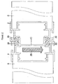
- FIG. 1 and 2 of the accompanying drawings Various connectors have been proposed for joining together such screen panels.
- FIGs 1 and 2 of the accompanying drawings respective panel end posts are mounted to the ends of respective screen panels 6, 8, and a link member 10 connects together the two panel end posts 2, 4.
- the link member 10 has a pair of flanges 12, 14 each having a channel 16, 18 provided therein. On the side walls of each channel is provided a groove 20 which faces an opposed groove 22 provided on the end posts 2, 4.
- the port 24 defined between these respective grooves receives a locking screw 26, as shown in Figure 2.
- the present invention in its various preferred embodiments seeks to overcome these various problems.
- a screen panel connector comprising a panel part and a link part, said respective parts having interengaging formations for locating said parts relative to one another and further comprising locking means for locking the parts together, said locking means comprising a locking port for receiving a locking fastener, said locking port being defined between respective formations provided in opposed surfaces of the respective parts, the link part formation being provided in an end face of the link.
- one of the locking formations is provided in the base of a channel formed in one of the respective parts, with the other part then extending into the channel, so that the locking port is defined within the bottom of the channel.
- This arrangement has the advantage of locating the respective parts with respect to one another and also in directing the locking forces in the desired direction, most preferably along the axis of the channel.
- the invention provides a screen panel connector comprising a panel part and a link part, said respective parts having interengaging formations for locating said parts relative to one another and further comprising locking means for locking the parts together, said locking means comprising a locking port for receiving a locking fastener, said locking port being defined between the respective parts at the base of a channel formed in one of said parts, the other part extending into said channel.
- this channel is formed on the panel connector part, most preferably facing directly away from the panel in use.
- a locating slot is provided which extends laterally from the mouth of the channel to receive a locating flange on the other part.
- a single slot may be provided to one side of the channel, but in other embodiments a pair of slots may be provided, one on each side of the channel.
- the connecting link may take a number of forms.
- the link may comprise a single limb which is provided with locking formations at its respective ends.
- the locking formations are substantially the same so that the link may be engaged with a corresponding connector part either way round.
- each link may comprise a pair of limbs each limb being provided with both locking formations at one or both ends thereof, the limbs being connected by a connecting web.
- the link part will be symmetrically about its longitudinal and transverse axis to allow it to be engaged with a corresponding panel connector panel part irrespective of its orientation relative thereto.
- the panel connector part this may be affixed to or adapted to fitted to the end of a screen panel.
- Each panel connector part may be provided with a plurality of locking formations.
- the connecting panel may have two locking formations provided in, for example, respective channels facing away from the panel body.
- the panel connector part may be adapted so that rather than, or in addition to having its locking formation facing axially away from the edge of the panel a formation is provided on a side wall of the panel connector part so that another panel may be connected to the first panel at an angle thereto, most preferably at 90°.
- the panel connector part may comprise locking formations which permit both edge to edge and edge to side connections. In such an arrangement, typically the respective locking formations may be formed at 90° to one another.
- the panel connector part may be integral with or attached to the panel. Preferably, it comprises an end post.
- the present invention also extends to a screen assembly comprising one or more connectors in accordance with the invention. Normally respective end posts will be attached to the ends of the panels to be joined and one or more link parts then extend between them. Generally the link part will extend generally parallel to the axis of the screen once assembled.
- the invention also extends to the individual components of the connector, more specifically in a further aspect to a link for connecting two screen panels together, comprising an end face provided with a locking formation which defines, with another connector part, a port for receiving a locking fastener.
- the link may have the preferred features as discussed above.
- the invention also extends in another aspect to a panel connector part attached to or adapted to be attached to a screen panel, said connector part comprising a channel with a locking formation for receiving a locking fastener in the base of said channel.
- panel connector part may have the features of the panel connectors as discussed above.
- Figures 1 and 2 show a prior art arrangement, which has been discussed in the above introduction, and as such need not be discussed further below.
- a screen panel 30 is provided at one end 32 with an end post 34.
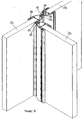
- the end post part 34 is formed as an extrusion, for example of aluminium or aluminium alloy, and extends along substantially the entire length of the panel edge 32, as shown in Figure 4.
- the end post part 34 is attached to the end of the edge 32 of the screen panel 30 by suitable means (not shown).
- the end post part 34 is provided with three connection formations 36, 38, 40. Each of these formations is adapted to receive a link part 42.
- a link part 42 (which is also an extruded part, for example of aluminium or aluminium alloy) is located at one end of the end post 34. It does not extend along the length of the end post part 34, and in fact, a second link part 42 will be provided at the other end of the end post part 34.
- the respective connector formations 36, 38 and 40 provided on the panel connector part 34 each comprise a channel 44 having a base wall 46 in which is formed a groove 48.
- the groove 48 defines, with a groove 50 arranged in the end face 52 of the link part 42 a locking port 54 for receiving a self tapping locking screw 56.
- the end of the link part 42 extends into the channel 44 part and is located generally laterally therein.
- Respective locating slots 58 are provided on the panel connector part, on either side of the mouth of the channel 44. These slots 58 receive locating flanges 60 provided on the link part 42. It will be understood that the interengagement of the locating flanges 60 and the locating slots 58 locates the respective connector parts axially, and to some extent, transversely.
- link part 42 The respective ends of the link part 42 are connected by a body part 62 which is received in an opening 64 in the connector formation.
- FIG 4 shows two screen panels 30 connected together by a pair of end post parts 34 and a link part 42. It will be noted from this Figure since the locking ports 48 are defined at the respective ends of the link part 42, the locking fasteners 56 are spaced apart substantially from one another meaning that they do not foul one another during tightening.
- first link part 42a is affixed to one end of one of the end posts 34a and is are secured thereto by a first locking screw 56.
- a second link member 42b is then located and secured at the opposite end of the other panel end post 34b and secured therein by a second fastener 56.
- the two panels 30 can then be brought together as shown by the arrow A such that the free ends of the respective links 42a, 42b enter the end posts 34a, 34b and assembly completed by insertion and tightening of a further locking screw 56.
- connection formations 38, 40 which are arranged to the side of the panels rather than opposite the edge of each panel can each receive a link 42.
- Such an arrangement is shown in Figure 6 where two screen panels 30 are joined end to end and a third panel 30 is joined to one of those at 90°.
- This arrangement has the advantage that it obviates a need for a separate corner post or linking extrusion. Should a side panel not be required, the connection formations 38,40 can be shut off by a cosmetic cover strip (not shown).
- an end post part 70 is suitably attached to the edge of a panel 72.
- the end post part 70 has a pair 74,76 of such formations.
- each of these formations 74, 76 comprises a channel 78, in whose base 80 is formed one half 82 of a screw port 84 for receiving respective self-tapping screw fasteners 86.
- a single locating slot 88, 90 is provided on the outer edge of the channel 76.
- the link part 92 comprises two limbs 94, 96 connected by a connecting web 98.
- Each limb 94, 96 of the link part 92 is generally similar to that of the earlier embodiment, with a locking formation 100 formed in the respective end faces thereof.
- only a single locating flange 98 is provided adjacent each end face for engagement within the locating slot 88, 90 provided on the end post part 70.
- end post part 70 can be adapted, as in the earlier embodiment, to allow for attachment of panels at 90° to each other.
Landscapes
- Engineering & Computer Science (AREA)
- Architecture (AREA)
- Physics & Mathematics (AREA)
- Electromagnetism (AREA)
- Civil Engineering (AREA)
- Structural Engineering (AREA)
- Connection Of Plates (AREA)
- Details Of Connecting Devices For Male And Female Coupling (AREA)
- Connector Housings Or Holding Contact Members (AREA)
Applications Claiming Priority (2)
| Application Number | Priority Date | Filing Date | Title |
|---|---|---|---|
| GB9909775 | 1999-04-28 | ||
| GB9909775A GB2349396B (en) | 1999-04-28 | 1999-04-28 | Screen panel connectors |
Publications (2)
| Publication Number | Publication Date |
|---|---|
| EP1048795A2 true EP1048795A2 (fr) | 2000-11-02 |
| EP1048795A3 EP1048795A3 (fr) | 2002-08-28 |
Family
ID=10852415
Family Applications (1)
| Application Number | Title | Priority Date | Filing Date |
|---|---|---|---|
| EP00303497A Withdrawn EP1048795A3 (fr) | 1999-04-28 | 2000-04-26 | Connecteurs pour panneaux d'écrans |
Country Status (2)
| Country | Link |
|---|---|
| EP (1) | EP1048795A3 (fr) |
| GB (1) | GB2349396B (fr) |
Cited By (8)
| Publication number | Priority date | Publication date | Assignee | Title |
|---|---|---|---|---|
| WO2003062547A1 (fr) * | 2002-01-24 | 2003-07-31 | Anthony Stansfield | Ensemble paroi demontable |
| RU2241806C2 (ru) * | 2002-10-10 | 2004-12-10 | Закрытое акционерное общество "НАЯДА" | Мобильная стеновая конструкция |
| RU2271421C2 (ru) * | 2004-05-06 | 2006-03-10 | Зао "Наяда" | Мобильная составная стеновая конструкция |
| DE202008008114U1 (de) | 2008-02-22 | 2009-05-28 | Serafini Besitz Gmbh & Co. Kg | Bausatz zur Erzeugung von Wandflächen-Regalsystemen |
| KR200464763Y1 (ko) | 2012-12-05 | 2013-01-22 | 주식회사 리바트 | 파티션용 빔 |
| EP3034710B1 (fr) * | 2014-12-18 | 2018-05-02 | Hartmut Sorg | Cadre en profilés de support destiné à fabriquer des structures mobiles temporaires |
| RU190990U1 (ru) * | 2019-05-17 | 2019-07-18 | Общество С Ограниченной Ответственностью "Аэрокарбон" | Устройство для соединения и фиксации двух профилей |
| US10400449B2 (en) | 2017-01-30 | 2019-09-03 | SkyPoint Ventures, LLC | Partitioning system for temporary and flexible-use structures |
Families Citing this family (3)
| Publication number | Priority date | Publication date | Assignee | Title |
|---|---|---|---|---|
| GB0106382D0 (en) * | 2001-03-15 | 2001-05-02 | Norwood Partition Systems Ltd | Jointing assembly |
| JP5595764B2 (ja) * | 2010-03-19 | 2014-09-24 | 文化シヤッター株式会社 | 間仕切ユニットの構造 |
| CN118814994B (zh) * | 2024-08-15 | 2025-05-09 | 华北理工大学 | 一种人防建设用轻质复合保温结构件 |
Family Cites Families (12)
| Publication number | Priority date | Publication date | Assignee | Title |
|---|---|---|---|---|
| NL300621A (fr) * | 1962-11-20 | |||
| DK122829B (da) * | 1970-05-01 | 1972-04-17 | P Bruun | Samling af mindst to bygningsdele samt fremgangsmåde til fremstilling af denne samling. |
| GB2065740A (en) * | 1979-12-07 | 1981-07-01 | Fletcher Timber Ltd | Modular building system and components therefor |
| GB2128707B (en) * | 1982-10-25 | 1986-05-29 | Concepts International | Screening |
| DE3523921A1 (de) * | 1985-07-04 | 1987-01-22 | Vaw Ver Aluminium Werke Ag | Verbundprofil und verfahren zu seiner herstellung |
| GB2193514B (en) * | 1986-08-07 | 1990-08-15 | Alan Cooper Limited | Panel |
| MY108560A (en) * | 1988-03-15 | 1996-10-31 | Artwright Ind Sdn Bhd | Panel surface end for system furniture |
| US4967531A (en) * | 1988-12-05 | 1990-11-06 | Lippert Holding Company | Wall partition units |
| US5864998A (en) * | 1989-12-26 | 1999-02-02 | Weston R. Loomer | Modular structural members |
| US5592794A (en) * | 1995-07-26 | 1997-01-14 | Tundaun; Apisit | Interlocking office panel device |
| US5904018A (en) * | 1996-06-20 | 1999-05-18 | Plamet Limited Liability Company | System of structural elements, particularly for building internal walls |
| DE19757089C1 (de) * | 1997-12-20 | 1999-04-08 | Bosch Gmbh Robert | Verbindungselement zum Verbinden von Profilstäben |
-
1999
- 1999-04-28 GB GB9909775A patent/GB2349396B/en not_active Expired - Lifetime
-
2000
- 2000-04-26 EP EP00303497A patent/EP1048795A3/fr not_active Withdrawn
Cited By (8)
| Publication number | Priority date | Publication date | Assignee | Title |
|---|---|---|---|---|
| WO2003062547A1 (fr) * | 2002-01-24 | 2003-07-31 | Anthony Stansfield | Ensemble paroi demontable |
| RU2241806C2 (ru) * | 2002-10-10 | 2004-12-10 | Закрытое акционерное общество "НАЯДА" | Мобильная стеновая конструкция |
| RU2271421C2 (ru) * | 2004-05-06 | 2006-03-10 | Зао "Наяда" | Мобильная составная стеновая конструкция |
| DE202008008114U1 (de) | 2008-02-22 | 2009-05-28 | Serafini Besitz Gmbh & Co. Kg | Bausatz zur Erzeugung von Wandflächen-Regalsystemen |
| KR200464763Y1 (ko) | 2012-12-05 | 2013-01-22 | 주식회사 리바트 | 파티션용 빔 |
| EP3034710B1 (fr) * | 2014-12-18 | 2018-05-02 | Hartmut Sorg | Cadre en profilés de support destiné à fabriquer des structures mobiles temporaires |
| US10400449B2 (en) | 2017-01-30 | 2019-09-03 | SkyPoint Ventures, LLC | Partitioning system for temporary and flexible-use structures |
| RU190990U1 (ru) * | 2019-05-17 | 2019-07-18 | Общество С Ограниченной Ответственностью "Аэрокарбон" | Устройство для соединения и фиксации двух профилей |
Also Published As
| Publication number | Publication date |
|---|---|
| GB2349396A (en) | 2000-11-01 |
| GB2349396B (en) | 2003-08-13 |
| GB9909775D0 (en) | 1999-06-23 |
| EP1048795A3 (fr) | 2002-08-28 |
Similar Documents
| Publication | Publication Date | Title |
|---|---|---|
| EP1048795A2 (fr) | Connecteurs pour panneaux d'écrans | |
| US7117647B2 (en) | System for constructing log structures | |
| US4733986A (en) | Splice plate for cable tray | |
| US5480117A (en) | Mounting bracket for wall panel locks | |
| CA2238453A1 (fr) | Element modulaire de bardage de poteau, ensemble de bardage de poteau, et methode de bardage | |
| US20040025459A1 (en) | Wall system, mounting plate and insert | |
| JPS63226432A (ja) | 可動間仕切壁 | |
| US20230392367A1 (en) | High Capacity Beam Hanger | |
| US7080492B1 (en) | Channel joint structural system | |
| US5096328A (en) | Fitting for dismountable connection of two construction elements | |
| US6041565A (en) | Door frame | |
| US5368426A (en) | Connector and method for edge-to-edge assembly of pressboard to form furniture structures | |
| EP0947434A3 (fr) | Récipient et panneaux de récipient | |
| AU622641B2 (en) | Panel edge strips | |
| JP2000129827A (ja) | 隔壁パネルの連結装置 | |
| GB2287517A (en) | Panel assembly system | |
| GB2413834A (en) | Framing system | |
| US12018506B1 (en) | Hidden interconnection arrangement of fence or railing and assembling method thereof | |
| GB2362661A (en) | Connecting building elements | |
| US6102638A (en) | Pre-assembled structural part and fastener | |
| EP0199858B1 (fr) | Joint dans des panneaux isolés préfabriqués | |
| JPH0735609U (ja) | 防音パネルの連結構造 | |
| EP0878590A3 (fr) | Jeu de pièces détachées et procédé pour l'érection de bâtiments | |
| JP2006183674A (ja) | 長手方向締結具、長手方向締結組立体およびその締結方法 | |
| JPH1054180A (ja) | ドアフレームと壁パネルとのジョイント構造 |
Legal Events
| Date | Code | Title | Description |
|---|---|---|---|
| PUAI | Public reference made under article 153(3) epc to a published international application that has entered the european phase |
Free format text: ORIGINAL CODE: 0009012 |
|
| AK | Designated contracting states |
Kind code of ref document: A2 Designated state(s): AT BE CH CY DE DK ES FI FR GB GR IE IT LI LU MC NL PT SE |
|
| AX | Request for extension of the european patent |
Free format text: AL;LT;LV;MK;RO;SI |
|
| PUAL | Search report despatched |
Free format text: ORIGINAL CODE: 0009013 |
|
| AK | Designated contracting states |
Kind code of ref document: A3 Designated state(s): AT BE CH CY DE DK ES FI FR GB GR IE IT LI LU MC NL PT SE |
|
| AX | Request for extension of the european patent |
Free format text: AL;LT;LV;MK;RO;SI |
|
| RIC1 | Information provided on ipc code assigned before grant |
Free format text: 7E 04B 2/74 A, 7E 04B 1/61 B |
|
| 17P | Request for examination filed |
Effective date: 20030228 |
|
| AKX | Designation fees paid |
Designated state(s): AT BE CH CY DE DK ES FI FR GB GR IE IT LI LU MC NL PT SE |
|
| 17Q | First examination report despatched |
Effective date: 20030425 |
|
| GRAP | Despatch of communication of intention to grant a patent |
Free format text: ORIGINAL CODE: EPIDOSNIGR1 |
|
| STAA | Information on the status of an ep patent application or granted ep patent |
Free format text: STATUS: THE APPLICATION IS DEEMED TO BE WITHDRAWN |
|
| 18D | Application deemed to be withdrawn |
Effective date: 20040817 |