EP1048880A1 - Lagerung für Achsen, Wellen oder dergleichen - Google Patents
Lagerung für Achsen, Wellen oder dergleichen Download PDFInfo
- Publication number
- EP1048880A1 EP1048880A1 EP00890135A EP00890135A EP1048880A1 EP 1048880 A1 EP1048880 A1 EP 1048880A1 EP 00890135 A EP00890135 A EP 00890135A EP 00890135 A EP00890135 A EP 00890135A EP 1048880 A1 EP1048880 A1 EP 1048880A1
- Authority
- EP
- European Patent Office
- Prior art keywords
- bearing
- sealing part
- static sealing
- axis
- pressure medium
- Prior art date
- Legal status (The legal status is an assumption and is not a legal conclusion. Google has not performed a legal analysis and makes no representation as to the accuracy of the status listed.)
- Granted
Links
- 238000007789 sealing Methods 0.000 claims abstract description 21
- 230000003068 static effect Effects 0.000 claims abstract description 18
- 239000012530 fluid Substances 0.000 abstract 2
- 239000002826 coolant Substances 0.000 description 3
- XLYOFNOQVPJJNP-UHFFFAOYSA-N water Substances O XLYOFNOQVPJJNP-UHFFFAOYSA-N 0.000 description 3
- 238000001816 cooling Methods 0.000 description 2
Images

Classifications
-
- F—MECHANICAL ENGINEERING; LIGHTING; HEATING; WEAPONS; BLASTING
- F16—ENGINEERING ELEMENTS AND UNITS; GENERAL MEASURES FOR PRODUCING AND MAINTAINING EFFECTIVE FUNCTIONING OF MACHINES OR INSTALLATIONS; THERMAL INSULATION IN GENERAL
- F16L—PIPES; JOINTS OR FITTINGS FOR PIPES; SUPPORTS FOR PIPES, CABLES OR PROTECTIVE TUBING; MEANS FOR THERMAL INSULATION IN GENERAL
- F16L39/00—Joints or fittings for double-walled or multi-channel pipes or pipe assemblies
- F16L39/04—Joints or fittings for double-walled or multi-channel pipes or pipe assemblies allowing adjustment or movement
-
- F—MECHANICAL ENGINEERING; LIGHTING; HEATING; WEAPONS; BLASTING
- F16—ENGINEERING ELEMENTS AND UNITS; GENERAL MEASURES FOR PRODUCING AND MAINTAINING EFFECTIVE FUNCTIONING OF MACHINES OR INSTALLATIONS; THERMAL INSULATION IN GENERAL
- F16L—PIPES; JOINTS OR FITTINGS FOR PIPES; SUPPORTS FOR PIPES, CABLES OR PROTECTIVE TUBING; MEANS FOR THERMAL INSULATION IN GENERAL
- F16L27/00—Adjustable joints; Joints allowing movement
- F16L27/08—Adjustable joints; Joints allowing movement allowing adjustment or movement only about the axis of one pipe
- F16L27/0804—Adjustable joints; Joints allowing movement allowing adjustment or movement only about the axis of one pipe the fluid passing axially from one joint element to another
- F16L27/0808—Adjustable joints; Joints allowing movement allowing adjustment or movement only about the axis of one pipe the fluid passing axially from one joint element to another the joint elements extending coaxially for some distance from their point of separation
- F16L27/0812—Adjustable joints; Joints allowing movement allowing adjustment or movement only about the axis of one pipe the fluid passing axially from one joint element to another the joint elements extending coaxially for some distance from their point of separation with slide bearings
- F16L27/082—Adjustable joints; Joints allowing movement allowing adjustment or movement only about the axis of one pipe the fluid passing axially from one joint element to another the joint elements extending coaxially for some distance from their point of separation with slide bearings having axial sealing
-
- F—MECHANICAL ENGINEERING; LIGHTING; HEATING; WEAPONS; BLASTING
- F16—ENGINEERING ELEMENTS AND UNITS; GENERAL MEASURES FOR PRODUCING AND MAINTAINING EFFECTIVE FUNCTIONING OF MACHINES OR INSTALLATIONS; THERMAL INSULATION IN GENERAL
- F16L—PIPES; JOINTS OR FITTINGS FOR PIPES; SUPPORTS FOR PIPES, CABLES OR PROTECTIVE TUBING; MEANS FOR THERMAL INSULATION IN GENERAL
- F16L27/00—Adjustable joints; Joints allowing movement
- F16L27/08—Adjustable joints; Joints allowing movement allowing adjustment or movement only about the axis of one pipe
- F16L27/0804—Adjustable joints; Joints allowing movement allowing adjustment or movement only about the axis of one pipe the fluid passing axially from one joint element to another
- F16L27/0808—Adjustable joints; Joints allowing movement allowing adjustment or movement only about the axis of one pipe the fluid passing axially from one joint element to another the joint elements extending coaxially for some distance from their point of separation
- F16L27/0824—Adjustable joints; Joints allowing movement allowing adjustment or movement only about the axis of one pipe the fluid passing axially from one joint element to another the joint elements extending coaxially for some distance from their point of separation with ball or roller bearings
- F16L27/0828—Adjustable joints; Joints allowing movement allowing adjustment or movement only about the axis of one pipe the fluid passing axially from one joint element to another the joint elements extending coaxially for some distance from their point of separation with ball or roller bearings having radial bearings
Definitions
- the invention relates to a bearing for axles, shafts or the like, the one Pressure medium is supplied via one or more lines, with one with the or the static sealing part connected to the lines, with a floating slide ring is provided.
- the invention has therefore set itself the goal of storing the aforementioned To create kind in which the known disadvantages do not occur.
- This goal is achieved in that the static sealing part with the seal carrier and the floating The slide ring can be removed without removing the bearing.
- This measure according to the invention makes it possible to arrange the entire arrangement of Install or remove outside without having to dismantle the bearing housing. Nevertheless, in the present invention, the mechanical seal is completely in the warehouse built-in.
- a preferred embodiment of the invention is in for the supply of pressure medium the axis arranged an intermediate bush.
- the invention is based on one shown in the drawings Embodiment with two-way arrangement and using a Embodiment shown with one-way arrangement. However, the invention is in no way limited to the exemplary embodiments shown.
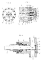
- FIG. 1 shows a bearing according to the invention with a two-way arrangement in cross-section
- Fig. 2 such a storage with two-way arrangement in view
- Fig. 3rd provides the detail of a static sealing part including seal carrier and slide rings in the Cross section in a two-way arrangement.
- Figures 4 to 6 relate Bearings according to the invention with a one-way arrangement: FIG. 4 shows a bearing in cross section, FIG. 5 a view and FIG. 6 the detail of a static sealing part together Seal carrier and slide rings in cross section.
- the static sealing part 1 is seated in the axis 2, which is in the bearing housing 3 is mounted on roller bearings 4.
- the cover 5 spans the screws 6 Intermediate cover 7, which receives the sealing element 8.
- the mother 9 spans the Ring 10 the inner ring of the bearing 4. With the connections 11 and 12, two rigid pipes (not shown) are arranged.
- the clamping sleeve 13 sits in the siphon tube 14 and is secured in two slots 15.
- the O-ring 21 is pressed through the housing cover 16 and the screws 17, whereby the Sealing is done.
- the cooling pressure medium (mostly water) passes through the connection 11 of the cover 5 into the arrangement and flows into the siphon tube 14, then cools the axis 2, returns in the Axis 2 around and flows back in the annular space between the siphon pipe 14 and the axis 2
- the pressure medium flows through the seal carrier 18, the floating slide ring 19, the static sealing part 1 and arrives at the connection 12, where it is in the rigid pipeline flows.
- Fig. 2 shows a view of the static sealing part 1 used, the screws 6 and Screws 17. Connections 11 and 12 open in cover 5.
- Fig. 3 shows a detail drawing of a section through the static sealing part 1.
- Das Coolant enters the assembly through port 11 and then flows into it Siphon tube 14.
- the cooling medium flows through the Seal carrier 18 finally to the connection 12, where it then in the (not shown) rigid pipeline flows.
- Fig. 4 shows in cross section an inventive bearing for axles with a one-way arrangement.
- the axis 22 is in a bearing housing 23 above one Roller bearings 24 stored.
- An intermediate cover 25 and the cover 26 are from Screws 27 held.
- the nut 28 holds the ring 29, which in turn is the inner ring spanned by the roller bearing 24.
- An intermediate bush 30 is screw 31 in the axis 22 held.
- the pressure medium (mostly water) emerges from a rigid pipe Terminal 32 of the lid 26 in the arrangement.
- the pressure medium flows in the static sealing part 33, which is located in the axis 22, passes the slide ring 34 and Seal carrier 35.
- the cooling pressure medium then flows through the Intermediate bushing 30 and the axis 22.
- the print medium flows through there, which is mirror-inverted arranged parts 23 to 35 until it is arranged at a connection to the 32nd Leaves mirror-inverted connection leaves to open into a fixed pipe.
- FIG. 5 shows a view of the static sealing part 33 used, the screws 27 and the Connection 32.
- FIG. 6 shows a detail drawing of a section through the static sealing part 33 already described above, the cooling medium reaches the port 32 in the Arrangement.
Landscapes
- General Engineering & Computer Science (AREA)
- Engineering & Computer Science (AREA)
- Mechanical Engineering (AREA)
- Sealing Of Bearings (AREA)
- Heat Treatment Of Articles (AREA)
- Vehicle Body Suspensions (AREA)
- Rolling Contact Bearings (AREA)
- Sealing Devices (AREA)
- Magnetic Bearings And Hydrostatic Bearings (AREA)
- Mounting Of Bearings Or Others (AREA)
- Spinning Or Twisting Of Yarns (AREA)
- Centrifugal Separators (AREA)
- Prostheses (AREA)
Abstract
Description
Claims (3)
- Lagerung für Achsen, Wellen oder dergleichen, der ein Druckmedium über ein oder mehrere Leitungen zugeführt wird, mit einem mit der oder den Leitungen verbundenen statischen Dichtteil, der mit einem schwebenden Gleitring versehen ist, dadurch gekennzeichnet, daß der statische Dichtteil (1 und 33) mit dem Dichtungsträger (18 und 35) und dem schwebenden Gleitring (19 und 34) ohne Lagerdemontage ausbaubar angeordnet ist
- Lagerung nach Anspruch 1, dadurch gekennzeichnet, daß zur Zufuhr von Druckmedium in der Achse (22) eine Zwischenbuchse (30) angeordnet ist.
- Lagerung nach Anspruch 1, dadurch gekennzeichnet, daß im statischen Dichtteil (1) zwei Wege angeordnet sind.
Priority Applications (3)
| Application Number | Priority Date | Filing Date | Title |
|---|---|---|---|
| DK00890135T DK1048880T3 (da) | 1999-04-28 | 2000-04-28 | Lejring til aksler, hjulaksler eller lignende |
| AT00890135T ATE269949T1 (de) | 1999-04-28 | 2000-04-28 | Lagerung für achsen, wellen oder dergleichen |
| DE20023231U DE20023231U1 (de) | 1999-04-28 | 2000-04-28 | Lagerung mit Drehdurchführung |
Applications Claiming Priority (2)
| Application Number | Priority Date | Filing Date | Title |
|---|---|---|---|
| AT75899 | 1999-04-28 | ||
| AT75899 | 1999-04-28 |
Publications (3)
| Publication Number | Publication Date |
|---|---|
| EP1048880A1 true EP1048880A1 (de) | 2000-11-02 |
| EP1048880B1 EP1048880B1 (de) | 2004-06-23 |
| EP1048880B2 EP1048880B2 (de) | 2015-11-04 |
Family
ID=3499027
Family Applications (1)
| Application Number | Title | Priority Date | Filing Date |
|---|---|---|---|
| EP00890135.7A Expired - Lifetime EP1048880B2 (de) | 1999-04-28 | 2000-04-28 | Lagerung für Achsen, Wellen oder dergleichen |
Country Status (6)
| Country | Link |
|---|---|
| EP (1) | EP1048880B2 (de) |
| AT (1) | ATE269949T1 (de) |
| DE (2) | DE20023231U1 (de) |
| DK (1) | DK1048880T3 (de) |
| ES (1) | ES2218100T3 (de) |
| PT (1) | PT1048880E (de) |
Cited By (5)
| Publication number | Priority date | Publication date | Assignee | Title |
|---|---|---|---|---|
| EP1613441A1 (de) | 2003-04-10 | 2006-01-11 | Fa. Georg Springmann Industrie- und Bergbautechnik GMBH | Vorrichtung zum ankuppeln einer kühlmittelzuführung an eine walze |
| EP1662191A1 (de) * | 2004-11-24 | 2006-05-31 | Deublin GmbH | Drehdurchführung |
| WO2011026957A1 (de) * | 2009-09-04 | 2011-03-10 | Georg Springmann Industrie- Und Bergbautechnik Gmbh | Rolle und rollenanordnung für eine stranggiessanlage |
| WO2011117383A1 (de) | 2010-03-26 | 2011-09-29 | Siemens Vai Metals Technologies Gmbh | Lagerung und dreheinführung für eine gekühlte rolle |
| CN103322204A (zh) * | 2013-06-29 | 2013-09-25 | 济钢集团有限公司 | 一种酸洗线破鳞拉矫机导向辊的轴承密封装置 |
Families Citing this family (2)
| Publication number | Priority date | Publication date | Assignee | Title |
|---|---|---|---|---|
| US7004509B2 (en) | 2001-07-02 | 2006-02-28 | The Johnson Corporation | Journal bearing mounted hub seal rotary joint |
| DE102015011978B4 (de) | 2015-09-14 | 2019-03-28 | M. E. E. GmbH | Drehdurchführung für die Durchführung eines fließfähigen Mediums |
Citations (11)
| Publication number | Priority date | Publication date | Assignee | Title |
|---|---|---|---|---|
| DE1915231A1 (de) * | 1969-03-26 | 1970-10-08 | Gottfried Svoboda | Dichtungskopf fuer rotierende Walzen |
| US3758179A (en) * | 1971-09-24 | 1973-09-11 | Basil Smith Seals Ltd | Mechanical shaft seal |
| DE2658134A1 (de) * | 1976-09-10 | 1977-12-01 | Rudisleben Chemieanlagenbau | Stationaere gleitringdichtung |
| DE3507819A1 (de) * | 1985-03-06 | 1986-09-11 | Manfred 4322 Sprockhövel Sade | Gleitringdichtung |
| EP0227282A1 (de) * | 1985-11-15 | 1987-07-01 | G.N. Burgess Engineering Limited | Vereinheitlichte Stirndichtungsvorrichtung |
| US4786061A (en) * | 1986-06-11 | 1988-11-22 | Hoechst Aktiengesellschaft | Safety rotary transmission with face seal |
| US4962577A (en) * | 1986-03-13 | 1990-10-16 | Eduard Kusters Maschinenfabrik Gmbh & Co. Kg | Work roll with improved support and lubricating system for an hydraulically supported roll |
| EP0519904B1 (de) | 1991-06-18 | 1995-07-19 | Voest-Alpine Industrieanlagenbau Gmbh | Anordnung zur Einführung von Druckmedien in Achsen, Wellen od. dgl. |
| AT400173B (de) | 1993-12-15 | 1995-10-25 | Hauer Ges M B H Ing | Lagerung für achsen, wellen od. dgl. |
| AT687U1 (de) | 1995-05-30 | 1996-03-25 | Deublin Gmbh | Anordnung zur einführung von druckmedien insbesondere in achsen oder wellen |
| DE29800616U1 (de) * | 1998-01-15 | 1998-03-05 | Depac Dichtungstechnik Gmbh, Bludenz | Sperrdruckdichtung |
-
2000
- 2000-04-28 DE DE20023231U patent/DE20023231U1/de not_active Expired - Lifetime
- 2000-04-28 DE DE50006867T patent/DE50006867D1/de not_active Expired - Lifetime
- 2000-04-28 PT PT00890135T patent/PT1048880E/pt unknown
- 2000-04-28 EP EP00890135.7A patent/EP1048880B2/de not_active Expired - Lifetime
- 2000-04-28 ES ES00890135T patent/ES2218100T3/es not_active Expired - Lifetime
- 2000-04-28 DK DK00890135T patent/DK1048880T3/da active
- 2000-04-28 AT AT00890135T patent/ATE269949T1/de active
Patent Citations (12)
| Publication number | Priority date | Publication date | Assignee | Title |
|---|---|---|---|---|
| DE1915231A1 (de) * | 1969-03-26 | 1970-10-08 | Gottfried Svoboda | Dichtungskopf fuer rotierende Walzen |
| US3758179A (en) * | 1971-09-24 | 1973-09-11 | Basil Smith Seals Ltd | Mechanical shaft seal |
| DE2658134A1 (de) * | 1976-09-10 | 1977-12-01 | Rudisleben Chemieanlagenbau | Stationaere gleitringdichtung |
| DE3507819A1 (de) * | 1985-03-06 | 1986-09-11 | Manfred 4322 Sprockhövel Sade | Gleitringdichtung |
| EP0227282A1 (de) * | 1985-11-15 | 1987-07-01 | G.N. Burgess Engineering Limited | Vereinheitlichte Stirndichtungsvorrichtung |
| US4962577A (en) * | 1986-03-13 | 1990-10-16 | Eduard Kusters Maschinenfabrik Gmbh & Co. Kg | Work roll with improved support and lubricating system for an hydraulically supported roll |
| US4786061A (en) * | 1986-06-11 | 1988-11-22 | Hoechst Aktiengesellschaft | Safety rotary transmission with face seal |
| EP0519904B1 (de) | 1991-06-18 | 1995-07-19 | Voest-Alpine Industrieanlagenbau Gmbh | Anordnung zur Einführung von Druckmedien in Achsen, Wellen od. dgl. |
| AT400173B (de) | 1993-12-15 | 1995-10-25 | Hauer Ges M B H Ing | Lagerung für achsen, wellen od. dgl. |
| AT687U1 (de) | 1995-05-30 | 1996-03-25 | Deublin Gmbh | Anordnung zur einführung von druckmedien insbesondere in achsen oder wellen |
| DE29609023U1 (de) | 1995-05-30 | 1996-08-22 | Deublin GmbH, 65719 Hofheim | Anordnung zur Einführung der Druckmedien in Achsen, Wellen o.dgl. |
| DE29800616U1 (de) * | 1998-01-15 | 1998-03-05 | Depac Dichtungstechnik Gmbh, Bludenz | Sperrdruckdichtung |
Cited By (16)
| Publication number | Priority date | Publication date | Assignee | Title |
|---|---|---|---|---|
| EP1613441B2 (de) † | 2003-04-10 | 2011-06-22 | Fa. Georg Springmann Industrie- und Bergbautechnik GMBH | Vorrichtung zum ankuppeln einer kühlmittelzuführung an eine walze |
| US7611169B2 (en) | 2003-04-10 | 2009-11-03 | Georg Springmann Industrie- Und Bergbautechnik Gmbh | Device for coupling a coolant supply to a roller |
| EP1613441A1 (de) | 2003-04-10 | 2006-01-11 | Fa. Georg Springmann Industrie- und Bergbautechnik GMBH | Vorrichtung zum ankuppeln einer kühlmittelzuführung an eine walze |
| EP1662191A1 (de) * | 2004-11-24 | 2006-05-31 | Deublin GmbH | Drehdurchführung |
| CN102216002B (zh) * | 2009-09-04 | 2015-03-04 | 乔格斯布林曼工业及采矿技术有限公司 | 用于连续铸造装置的滚轴及滚轴配置 |
| CN102216002A (zh) * | 2009-09-04 | 2011-10-12 | 乔格斯布林曼工业及采矿技术有限公司 | 用于连续铸造装置的滚轴及滚轴配置 |
| US8267154B2 (en) | 2009-09-04 | 2012-09-18 | Georg Springmann Industrie- Und Bergbautechnik Gmbh | Roll and roll arrangement for a continuous casting installation |
| TWI465302B (zh) * | 2009-09-04 | 2014-12-21 | Georg Springmann Ind Und Bergbautechnik Gmbh | 連續鑄造裝置用之滾軸及滾軸配置 |
| EA020786B1 (ru) * | 2009-09-04 | 2015-01-30 | Георг Шпрингманн Индустри-Унд Бергбаутехник Гмбх | Валок и валковая система для установки непрерывной разливки стали |
| WO2011026957A1 (de) * | 2009-09-04 | 2011-03-10 | Georg Springmann Industrie- Und Bergbautechnik Gmbh | Rolle und rollenanordnung für eine stranggiessanlage |
| EP2473298B1 (de) | 2009-09-04 | 2015-11-11 | Georg Springmann Industrie- und Bergbautechnik GMBH | Rolle und rollenanordnung für eine stranggiessanlage |
| WO2011117383A1 (de) | 2010-03-26 | 2011-09-29 | Siemens Vai Metals Technologies Gmbh | Lagerung und dreheinführung für eine gekühlte rolle |
| CN102812279A (zh) * | 2010-03-26 | 2012-12-05 | 西门子Vai金属科技有限责任公司 | 用于被冷却的辊子的支承结构和旋转引入机构 |
| CN102812279B (zh) * | 2010-03-26 | 2015-11-25 | 西门子Vai金属科技有限责任公司 | 用于被冷却的辊子的支承结构和旋转引入机构 |
| CN103322204A (zh) * | 2013-06-29 | 2013-09-25 | 济钢集团有限公司 | 一种酸洗线破鳞拉矫机导向辊的轴承密封装置 |
| CN103322204B (zh) * | 2013-06-29 | 2015-10-21 | 济钢集团有限公司 | 一种酸洗线破鳞拉矫机导向辊的轴承密封装置 |
Also Published As
| Publication number | Publication date |
|---|---|
| ES2218100T3 (es) | 2004-11-16 |
| EP1048880B2 (de) | 2015-11-04 |
| DE20023231U1 (de) | 2003-07-10 |
| EP1048880B1 (de) | 2004-06-23 |
| DE50006867D1 (de) | 2004-07-29 |
| DK1048880T3 (da) | 2004-11-08 |
| ATE269949T1 (de) | 2004-07-15 |
| PT1048880E (pt) | 2004-09-30 |
Similar Documents
| Publication | Publication Date | Title |
|---|---|---|
| DE69716879T2 (de) | Tankreinigungsvorrichtung | |
| EP1048880A1 (de) | Lagerung für Achsen, Wellen oder dergleichen | |
| DE2637179A1 (de) | Strangfuehrung an einer stranggiessanlage | |
| EP0498193B1 (de) | Einrichtung zur Montage einer Wannenbatterie in einer Einbaunische zwischen der Seitenwand einer Badewanne und einer Mauer des Badezimmers oder dergleichen | |
| DE2035698A1 (en) | Roll neck bearings - changed rapidly using a bayonet-type connection | |
| DE102004056818B3 (de) | Drehdurchführung | |
| DE19840043C1 (de) | Drehdurchführung mit Kugelkopf | |
| AT687U1 (de) | Anordnung zur einführung von druckmedien insbesondere in achsen oder wellen | |
| DE2823520A1 (de) | Dichtungsanordnung fuer in lagern gelagerte wellen | |
| EP0355301B1 (de) | Absperrschieber | |
| WO2003044415A1 (de) | Anschlussblock für hydraulik-versorgungsleitungen der hydrostatikanlage eines ölfilmlagers | |
| EP3917867B1 (de) | Vorrichtung zum auf- und abwickeln eines schlauchs | |
| DE2345637A1 (de) | Turbine | |
| DE9014487U1 (de) | Im Gehäuse eines Druckraumes drehbar gelagerte Welle | |
| DE9415871U1 (de) | Winkeldrehgelenk mit verbesserter Abdichtung | |
| DE19841712B4 (de) | Walzenanordnung | |
| DE2004392A1 (en) | Agitator shaft seal changeable withoutdepressurising vessel | |
| DE19823669C1 (de) | Kompensator-Dreheinführung | |
| DE19963496A1 (de) | Vorrichtung zum Reinigen mit einer rotierenden Düse | |
| DE1528725C3 (de) | Vorrichtung zur Entnahme von Zwischendruck an einer mehrstufigen Kreiselpumpe | |
| DE3514899A1 (de) | Vorrichtung zur umkehrung der stroemungsrichtung von fluessigkeiten | |
| DE4444719A1 (de) | Dichtungsvorrichtung für eine durch eine Wand geführte Welle | |
| EP0605778B1 (de) | Vorrichtung zum Auswechseln eines in einer Rohrleitung angeordneten Aggregates | |
| DE8712550U1 (de) | Steuerantrieb für eine in einer rotierenden Werkzeugmaschinenspindel axial verschiebbare, hohle Steuerstange | |
| DE1757921A1 (de) | Ruehrwerk mit verschiebbarer Ruehrerwelle |
Legal Events
| Date | Code | Title | Description |
|---|---|---|---|
| PUAI | Public reference made under article 153(3) epc to a published international application that has entered the european phase |
Free format text: ORIGINAL CODE: 0009012 |
|
| AK | Designated contracting states |
Kind code of ref document: A1 Designated state(s): AT BE CH CY DE DK ES FI FR GB GR IE IT LI LU MC NL PT SE |
|
| AX | Request for extension of the european patent |
Free format text: AL;LT;LV;MK;RO;SI |
|
| 17P | Request for examination filed |
Effective date: 20010427 |
|
| AKX | Designation fees paid |
Free format text: AT BE CH CY DE DK ES FI FR GB GR IE IT LI LU MC NL PT SE |
|
| 17Q | First examination report despatched |
Effective date: 20030530 |
|
| GRAP | Despatch of communication of intention to grant a patent |
Free format text: ORIGINAL CODE: EPIDOSNIGR1 |
|
| GRAS | Grant fee paid |
Free format text: ORIGINAL CODE: EPIDOSNIGR3 |
|
| GRAA | (expected) grant |
Free format text: ORIGINAL CODE: 0009210 |
|
| AK | Designated contracting states |
Kind code of ref document: B1 Designated state(s): AT BE CH CY DE DK ES FI FR GB GR IE IT LI LU MC NL PT SE |
|
| REG | Reference to a national code |
Ref country code: GB Ref legal event code: FG4D Free format text: NOT ENGLISH |
|
| REG | Reference to a national code |
Ref country code: CH Ref legal event code: EP |
|
| REG | Reference to a national code |
Ref country code: CH Ref legal event code: NV Representative=s name: BOVARD AG PATENTANWAELTE |
|
| REG | Reference to a national code |
Ref country code: IE Ref legal event code: FG4D Free format text: GERMAN |
|
| REF | Corresponds to: |
Ref document number: 50006867 Country of ref document: DE Date of ref document: 20040729 Kind code of ref document: P |
|
| GBT | Gb: translation of ep patent filed (gb section 77(6)(a)/1977) |
Effective date: 20040728 |
|
| REG | Reference to a national code |
Ref country code: SE Ref legal event code: TRGR |
|
| REG | Reference to a national code |
Ref country code: PT Ref legal event code: SC4A Free format text: AVAILABILITY OF NATIONAL TRANSLATION Effective date: 20040806 |
|
| REG | Reference to a national code |
Ref country code: GR Ref legal event code: EP Ref document number: 20040402966 Country of ref document: GR |
|
| REG | Reference to a national code |
Ref country code: DK Ref legal event code: T3 |
|
| REG | Reference to a national code |
Ref country code: ES Ref legal event code: FG2A Ref document number: 2218100 Country of ref document: ES Kind code of ref document: T3 |
|
| ET | Fr: translation filed | ||
| PLAQ | Examination of admissibility of opposition: information related to despatch of communication + time limit deleted |
Free format text: ORIGINAL CODE: EPIDOSDOPE2 |
|
| PLBI | Opposition filed |
Free format text: ORIGINAL CODE: 0009260 |
|
| PLBQ | Unpublished change to opponent data |
Free format text: ORIGINAL CODE: EPIDOS OPPO |
|
| PLAQ | Examination of admissibility of opposition: information related to despatch of communication + time limit deleted |
Free format text: ORIGINAL CODE: EPIDOSDOPE2 |
|
| PLAR | Examination of admissibility of opposition: information related to receipt of reply deleted |
Free format text: ORIGINAL CODE: EPIDOSDOPE4 |
|
| PLBQ | Unpublished change to opponent data |
Free format text: ORIGINAL CODE: EPIDOS OPPO |
|
| PLAB | Opposition data, opponent's data or that of the opponent's representative modified |
Free format text: ORIGINAL CODE: 0009299OPPO |
|
| PLAQ | Examination of admissibility of opposition: information related to despatch of communication + time limit deleted |
Free format text: ORIGINAL CODE: EPIDOSDOPE2 |
|
| PLAR | Examination of admissibility of opposition: information related to receipt of reply deleted |
Free format text: ORIGINAL CODE: EPIDOSDOPE4 |
|
| PLBI | Opposition filed |
Free format text: ORIGINAL CODE: 0009260 |
|
| PLBQ | Unpublished change to opponent data |
Free format text: ORIGINAL CODE: EPIDOS OPPO |
|
| PLAB | Opposition data, opponent's data or that of the opponent's representative modified |
Free format text: ORIGINAL CODE: 0009299OPPO |
|
| 26 | Opposition filed |
Opponent name: SMS DEMAG AG Effective date: 20050315 |
|
| PLAX | Notice of opposition and request to file observation + time limit sent |
Free format text: ORIGINAL CODE: EPIDOSNOBS2 |
|
| R26 | Opposition filed (corrected) |
Opponent name: SMS DEMAG AG Effective date: 20050315 |
|
| 26 | Opposition filed |
Opponent name: SMS DEMAG AG Effective date: 20050315 Opponent name: THE JOHNSON CORPORATION Effective date: 20050322 |
|
| R26 | Opposition filed (corrected) |
Opponent name: THE JOHNSON CORPORATION Effective date: 20050322 Opponent name: SMS DEMAG AG Effective date: 20050315 |
|
| NLR1 | Nl: opposition has been filed with the epo |
Opponent name: THE JOHNSON CORPORATION Opponent name: SMS DEMAG AG |
|
| NLR1 | Nl: opposition has been filed with the epo |
Opponent name: SMS DEMAG AG Opponent name: THE JOHNSON CORPORATION |
|
| PLBB | Reply of patent proprietor to notice(s) of opposition received |
Free format text: ORIGINAL CODE: EPIDOSNOBS3 |
|
| PLAB | Opposition data, opponent's data or that of the opponent's representative modified |
Free format text: ORIGINAL CODE: 0009299OPPO |
|
| R26 | Opposition filed (corrected) |
Opponent name: KADANT JOHNSON INC. Effective date: 20050322 Opponent name: SMS DEMAG AG Effective date: 20050315 |
|
| NLR1 | Nl: opposition has been filed with the epo |
Opponent name: SMS DEMAG AG Opponent name: KADANT JOHNSON INC. |
|
| PGFP | Annual fee paid to national office [announced via postgrant information from national office to epo] |
Ref country code: CY Payment date: 20070320 Year of fee payment: 8 |
|
| PGFP | Annual fee paid to national office [announced via postgrant information from national office to epo] |
Ref country code: PT Payment date: 20070321 Year of fee payment: 8 |
|
| PGFP | Annual fee paid to national office [announced via postgrant information from national office to epo] |
Ref country code: MC Payment date: 20070322 Year of fee payment: 8 |
|
| PLAB | Opposition data, opponent's data or that of the opponent's representative modified |
Free format text: ORIGINAL CODE: 0009299OPPO |
|
| PGFP | Annual fee paid to national office [announced via postgrant information from national office to epo] |
Ref country code: FI Payment date: 20070412 Year of fee payment: 8 Ref country code: IE Payment date: 20070412 Year of fee payment: 8 |
|
| PGFP | Annual fee paid to national office [announced via postgrant information from national office to epo] |
Ref country code: SE Payment date: 20070416 Year of fee payment: 8 |
|
| PGFP | Annual fee paid to national office [announced via postgrant information from national office to epo] |
Ref country code: LU Payment date: 20070417 Year of fee payment: 8 |
|
| PGFP | Annual fee paid to national office [announced via postgrant information from national office to epo] |
Ref country code: DK Payment date: 20070418 Year of fee payment: 8 Ref country code: ES Payment date: 20070418 Year of fee payment: 8 Ref country code: NL Payment date: 20070418 Year of fee payment: 8 |
|
| R26 | Opposition filed (corrected) |
Opponent name: KADANT JOHNSON INC. Effective date: 20050322 Opponent name: SMS DEMAG AG Effective date: 20050315 |
|
| NLR1 | Nl: opposition has been filed with the epo |
Opponent name: KADANT JOHNSON INC. Opponent name: SMS DEMAG AG |
|
| PGFP | Annual fee paid to national office [announced via postgrant information from national office to epo] |
Ref country code: GR Payment date: 20070329 Year of fee payment: 8 |
|
| PLAB | Opposition data, opponent's data or that of the opponent's representative modified |
Free format text: ORIGINAL CODE: 0009299OPPO |
|
| REG | Reference to a national code |
Ref country code: PT Ref legal event code: MM4A Free format text: LAPSE DUE TO NON-PAYMENT OF FEES Effective date: 20081028 |
|
| PG25 | Lapsed in a contracting state [announced via postgrant information from national office to epo] |
Ref country code: MC Free format text: LAPSE BECAUSE OF NON-PAYMENT OF DUE FEES Effective date: 20080430 |
|
| REG | Reference to a national code |
Ref country code: DK Ref legal event code: EBP |
|
| EUG | Se: european patent has lapsed | ||
| NLV4 | Nl: lapsed or anulled due to non-payment of the annual fee |
Effective date: 20081101 |
|
| PG25 | Lapsed in a contracting state [announced via postgrant information from national office to epo] |
Ref country code: NL Free format text: LAPSE BECAUSE OF NON-PAYMENT OF DUE FEES Effective date: 20081101 Ref country code: PT Free format text: LAPSE BECAUSE OF NON-PAYMENT OF DUE FEES Effective date: 20081028 |
|
| REG | Reference to a national code |
Ref country code: IE Ref legal event code: MM4A |
|
| PG25 | Lapsed in a contracting state [announced via postgrant information from national office to epo] |
Ref country code: FI Free format text: LAPSE BECAUSE OF NON-PAYMENT OF DUE FEES Effective date: 20080428 |
|
| PG25 | Lapsed in a contracting state [announced via postgrant information from national office to epo] |
Ref country code: CY Free format text: LAPSE BECAUSE OF NON-PAYMENT OF DUE FEES Effective date: 20080428 |
|
| PG25 | Lapsed in a contracting state [announced via postgrant information from national office to epo] |
Ref country code: IE Free format text: LAPSE BECAUSE OF NON-PAYMENT OF DUE FEES Effective date: 20080428 Ref country code: DK Free format text: LAPSE BECAUSE OF NON-PAYMENT OF DUE FEES Effective date: 20080430 |
|
| REG | Reference to a national code |
Ref country code: ES Ref legal event code: FD2A Effective date: 20080429 |
|
| PG25 | Lapsed in a contracting state [announced via postgrant information from national office to epo] |
Ref country code: GR Free format text: LAPSE BECAUSE OF NON-PAYMENT OF DUE FEES Effective date: 20081104 |
|
| PG25 | Lapsed in a contracting state [announced via postgrant information from national office to epo] |
Ref country code: ES Free format text: LAPSE BECAUSE OF NON-PAYMENT OF DUE FEES Effective date: 20080429 |
|
| PLAB | Opposition data, opponent's data or that of the opponent's representative modified |
Free format text: ORIGINAL CODE: 0009299OPPO |
|
| R26 | Opposition filed (corrected) |
Opponent name: SMS DEMAG AG Effective date: 20050315 Opponent name: KADANT JOHNSON INC. Effective date: 20050322 |
|
| PG25 | Lapsed in a contracting state [announced via postgrant information from national office to epo] |
Ref country code: LU Free format text: LAPSE BECAUSE OF NON-PAYMENT OF DUE FEES Effective date: 20080428 |
|
| PG25 | Lapsed in a contracting state [announced via postgrant information from national office to epo] |
Ref country code: SE Free format text: LAPSE BECAUSE OF NON-PAYMENT OF DUE FEES Effective date: 20080429 |
|
| APBM | Appeal reference recorded |
Free format text: ORIGINAL CODE: EPIDOSNREFNO |
|
| APBP | Date of receipt of notice of appeal recorded |
Free format text: ORIGINAL CODE: EPIDOSNNOA2O |
|
| APAH | Appeal reference modified |
Free format text: ORIGINAL CODE: EPIDOSCREFNO |
|
| APBQ | Date of receipt of statement of grounds of appeal recorded |
Free format text: ORIGINAL CODE: EPIDOSNNOA3O |
|
| REG | Reference to a national code |
Ref country code: CH Ref legal event code: PFA Owner name: DEUBLIN GMBH Free format text: DEUBLIN GMBH#NASSAUSTRASSE 10#65719 HOFHEIM-WALLAU (DE) -TRANSFER TO- DEUBLIN GMBH#NASSAUSTRASSE 10#65719 HOFHEIM-WALLAU (DE) |
|
| PLAB | Opposition data, opponent's data or that of the opponent's representative modified |
Free format text: ORIGINAL CODE: 0009299OPPO |
|
| R26 | Opposition filed (corrected) |
Opponent name: KADANT JOHNSON INC. Effective date: 20050322 Opponent name: SMS SIEMAG AKTIENGESELLSCHAFT Effective date: 20050315 |
|
| APBU | Appeal procedure closed |
Free format text: ORIGINAL CODE: EPIDOSNNOA9O |
|
| REG | Reference to a national code |
Ref country code: FR Ref legal event code: PLFP Year of fee payment: 16 |
|
| PLAB | Opposition data, opponent's data or that of the opponent's representative modified |
Free format text: ORIGINAL CODE: 0009299OPPO |
|
| R26 | Opposition filed (corrected) |
Opponent name: SMS GROUP GMBH Effective date: 20050315 |
|
| PUAH | Patent maintained in amended form |
Free format text: ORIGINAL CODE: 0009272 |
|
| STAA | Information on the status of an ep patent application or granted ep patent |
Free format text: STATUS: PATENT MAINTAINED AS AMENDED |
|
| 27A | Patent maintained in amended form |
Effective date: 20151104 |
|
| AK | Designated contracting states |
Kind code of ref document: B2 Designated state(s): AT BE CH CY DE DK ES FI FR GB GR IE IT LI LU MC NL PT SE |
|
| REG | Reference to a national code |
Ref country code: DE Ref legal event code: R102 Ref document number: 50006867 Country of ref document: DE |
|
| REG | Reference to a national code |
Ref country code: CH Ref legal event code: AELC |
|
| REG | Reference to a national code |
Ref country code: FR Ref legal event code: PLFP Year of fee payment: 17 |
|
| PG25 | Lapsed in a contracting state [announced via postgrant information from national office to epo] |
Ref country code: GR Free format text: LAPSE BECAUSE OF FAILURE TO SUBMIT A TRANSLATION OF THE DESCRIPTION OR TO PAY THE FEE WITHIN THE PRESCRIBED TIME-LIMIT Effective date: 20160205 |
|
| REG | Reference to a national code |
Ref country code: FR Ref legal event code: PLFP Year of fee payment: 18 |
|
| REG | Reference to a national code |
Ref country code: FR Ref legal event code: PLFP Year of fee payment: 19 |
|
| PGFP | Annual fee paid to national office [announced via postgrant information from national office to epo] |
Ref country code: DE Payment date: 20190427 Year of fee payment: 20 Ref country code: IT Payment date: 20190419 Year of fee payment: 20 |
|
| PGFP | Annual fee paid to national office [announced via postgrant information from national office to epo] |
Ref country code: FR Payment date: 20190423 Year of fee payment: 20 Ref country code: BE Payment date: 20190418 Year of fee payment: 20 |
|
| PGFP | Annual fee paid to national office [announced via postgrant information from national office to epo] |
Ref country code: CH Payment date: 20190424 Year of fee payment: 20 |
|
| PGFP | Annual fee paid to national office [announced via postgrant information from national office to epo] |
Ref country code: AT Payment date: 20190416 Year of fee payment: 20 Ref country code: GB Payment date: 20190424 Year of fee payment: 20 |
|
| REG | Reference to a national code |
Ref country code: DE Ref legal event code: R071 Ref document number: 50006867 Country of ref document: DE |
|
| REG | Reference to a national code |
Ref country code: CH Ref legal event code: PL |
|
| REG | Reference to a national code |
Ref country code: GB Ref legal event code: PE20 Expiry date: 20200427 |
|
| REG | Reference to a national code |
Ref country code: BE Ref legal event code: MK Effective date: 20200428 |
|
| REG | Reference to a national code |
Ref country code: AT Ref legal event code: MK07 Ref document number: 269949 Country of ref document: AT Kind code of ref document: T Effective date: 20200428 |
|
| PG25 | Lapsed in a contracting state [announced via postgrant information from national office to epo] |
Ref country code: GB Free format text: LAPSE BECAUSE OF EXPIRATION OF PROTECTION Effective date: 20200427 |