EP1048965A2 - Optischer Modul Verbinder - Google Patents
Optischer Modul Verbinder Download PDFInfo
- Publication number
- EP1048965A2 EP1048965A2 EP00303643A EP00303643A EP1048965A2 EP 1048965 A2 EP1048965 A2 EP 1048965A2 EP 00303643 A EP00303643 A EP 00303643A EP 00303643 A EP00303643 A EP 00303643A EP 1048965 A2 EP1048965 A2 EP 1048965A2
- Authority
- EP
- European Patent Office
- Prior art keywords
- connector
- optical
- connector module
- holder
- cover member
- Prior art date
- Legal status (The legal status is an assumption and is not a legal conclusion. Google has not performed a legal analysis and makes no representation as to the accuracy of the status listed.)
- Granted
Links
Images


Classifications
-
- G—PHYSICS
- G02—OPTICS
- G02B—OPTICAL ELEMENTS, SYSTEMS OR APPARATUS
- G02B6/00—Light guides; Structural details of arrangements comprising light guides and other optical elements, e.g. couplings
- G02B6/24—Coupling light guides
- G02B6/36—Mechanical coupling means
- G02B6/38—Mechanical coupling means having fibre to fibre mating means
- G02B6/3807—Dismountable connectors, i.e. comprising plugs
- G02B6/389—Dismountable connectors, i.e. comprising plugs characterised by the method of fastening connecting plugs and sockets, e.g. screw- or nut-lock, snap-in, bayonet type
- G02B6/3893—Push-pull type, e.g. snap-in, push-on
-
- G—PHYSICS
- G02—OPTICS
- G02B—OPTICAL ELEMENTS, SYSTEMS OR APPARATUS
- G02B6/00—Light guides; Structural details of arrangements comprising light guides and other optical elements, e.g. couplings
- G02B6/24—Coupling light guides
- G02B6/42—Coupling light guides with opto-electronic elements
-
- G—PHYSICS
- G02—OPTICS
- G02B—OPTICAL ELEMENTS, SYSTEMS OR APPARATUS
- G02B6/00—Light guides; Structural details of arrangements comprising light guides and other optical elements, e.g. couplings
- G02B6/24—Coupling light guides
- G02B6/42—Coupling light guides with opto-electronic elements
- G02B6/4201—Packages, e.g. shape, construction, internal or external details
- G02B6/4249—Packages, e.g. shape, construction, internal or external details comprising arrays of active devices and fibres
-
- G—PHYSICS
- G02—OPTICS
- G02B—OPTICAL ELEMENTS, SYSTEMS OR APPARATUS
- G02B6/00—Light guides; Structural details of arrangements comprising light guides and other optical elements, e.g. couplings
- G02B6/24—Coupling light guides
- G02B6/42—Coupling light guides with opto-electronic elements
- G02B6/4292—Coupling light guides with opto-electronic elements the light guide being disconnectable from the opto-electronic element, e.g. mutually self aligning arrangements
-
- G—PHYSICS
- G02—OPTICS
- G02B—OPTICAL ELEMENTS, SYSTEMS OR APPARATUS
- G02B6/00—Light guides; Structural details of arrangements comprising light guides and other optical elements, e.g. couplings
- G02B6/24—Coupling light guides
- G02B6/36—Mechanical coupling means
- G02B6/38—Mechanical coupling means having fibre to fibre mating means
- G02B6/3807—Dismountable connectors, i.e. comprising plugs
- G02B6/381—Dismountable connectors, i.e. comprising plugs of the ferrule type, e.g. fibre ends embedded in ferrules, connecting a pair of fibres
- G02B6/3817—Dismountable connectors, i.e. comprising plugs of the ferrule type, e.g. fibre ends embedded in ferrules, connecting a pair of fibres containing optical and electrical conductors
-
- G—PHYSICS
- G02—OPTICS
- G02B—OPTICAL ELEMENTS, SYSTEMS OR APPARATUS
- G02B6/00—Light guides; Structural details of arrangements comprising light guides and other optical elements, e.g. couplings
- G02B6/24—Coupling light guides
- G02B6/36—Mechanical coupling means
- G02B6/38—Mechanical coupling means having fibre to fibre mating means
- G02B6/3807—Dismountable connectors, i.e. comprising plugs
- G02B6/3873—Connectors using guide surfaces for aligning ferrule ends, e.g. tubes, sleeves, V-grooves, rods, pins, balls
- G02B6/3885—Multicore or multichannel optical connectors, i.e. one single ferrule containing more than one fibre, e.g. ribbon type
Definitions
- the present invention relates to an optical connector module for coupling optical devices and optical fibers, and more particularly, to an optical connector module having a slim design.
- Optical connector modules guide light transmission by coupling optical fibers and optical devices.
- the optical devices serve as a light source for converting electrical signals into optical signals and/or a photodetector for receiving light transmitted through optical fibers and converting the optical signals into electrical signals.
- the light devices are usually in the form of an array.
- Such an optical connector module is installed between devices for information transfer through optical transmission, for example, between a computer and a bus or a monitor, or between buses.
- the optical connector module is adapted to an optical transmission module employing a plurality of channels in the form of an array for independent light transmission.
- FIG. 1 illustrates an optical connector module suggested by the inventors of the present application.
- the optical connector module includes a holder 30 having an optical device 21 and an electrode 23, a connector 50 for receiving optical fibers 60, and a housing 40 having an opening 43 for insertion of the holder 20 and the connector 50 thereinto.
- a coupling side 33 carrying the optical device 21 is inserted into the opening 43 of the housing 40.
- the connector 50 has a pair of flexible portions 51 with latches 53 at the sides thereof.
- the latches 53 of the connector 50 interact with latch-receiving grooves 45 formed at the housing 40, which maintains the connector 50 within the housing 40.
- reference posts 41 disposed at one side of the housing 40 engage with corresponding reference holes 31 formed at the holder 30, which ensures accurate alignment between the optical device 21 and the optical fibers 60.
- the optical device 21 must be attached to the holder 30 by die bonding and subjected to wire bonding, prior to the insertion of the holder 30 into the housing 40.
- the bonding process there are difficulties during the bonding process in jigging a relatively small holder 30 and in accurately aligning optical fibers to optical devices due to the absence of reference points for guiding the coupling.
- an optical connector module comprising: a holder including at least one optical device and electrode; a connector having at least one optical fiber for light transmission, to correspond to the optical device, and latches; and a body in an open structure without top and bottom plates, having a base, a pair of sidewall portions extending from the base, a binding space for receiving the holder and the connector such that the input/output ends of the optical fiber of the connector are aligned to the optical device of the holder, and latch-receiving grooves on the sidewall portions to receive the latches of the connector.
- the optical connector module further comprises means for guiding the connector to an accurate position within the binding space of the body.
- the means for guiding the connector may comprise: guide projections on both the outer sides of the connector or on both the inner sides of the sidewall portions of the body; and guide grooves on both the inner sides of the side wall portions of the body or on both the outer sides of the connector, the guide grooves for slidably receiving corresponding guide projections.
- the means for guiding the connector may comprise: a pair of round guide portions at at least the leading parts on the sides of the connector; and a pair of round guide grooves on the inner walls of the sidewall portions of the body, to correspond to the round guide portions, the round guide grooves for slidably receiving the round guide portions.
- the pair of round guide grooves have different curvatures
- the pair of round guide portions on the connector have different curvatures to correspond to those of the round guide grooves, to indicate an appropriate insertion direction of the connector into the body.
- the optical connector module further comprises: a first electrode member on the leading side of the connector, on which the input/output ends of the optical fiber are arranged, the first electrode member being electrically connected to electric wires supported by the connector; and a second electrode member on the holder, being formed corresponding to the first electrode member, wherein as the holder and the connector are combined with the body, the first and second electrode members are electrically coupled to transmit an electrical signal.
- the optical connector module further comprises a cover member being opened downward to cap the body with the connector and holder.
- the cover member may have flanges at the bottom edges of both sides thereof, for use in attaching the optical connector module to a predetermined device.
- an optical connector module comprising: a connecting unit in which at least one optical device is coupled to at least one optical fiber; and a cover member being opened downward, capping the top and two sides of the connecting unit and fixed to the top of the substrate of a predetermined device to stably maintain the combination of the connecting unit within the cover member, wherein the cover member forms a support structure of the connecting unit along with the substrate of the device.
- the connecting unit is designed to enable attachment and detachment of the optical fiber or the optical device to and from the connecting unit
- the cover member has at least one open side to enable attachment and detachment of the optical fiber or the optical device to and from the connecting unit.
- an optical connector module in accordance with a preferred embodiment of the present invention includes a holder 120 for receiving at least one optical device 121 and leads 125, a connector 140 for receiving at least one optical fiber for light transmission, and a body 100 for accommodating the holder 120 and the connector 140 such that the optical devices 121 mate with the input/output ends of optical fibers 150. It is preferable that the optical connector module further includes a cover member 160 for holding the combination of the holder 120 and the connector 140 in the body 110 and attaching the optical connector module to a predetermined device. In this case, the holder 120, the connector 140 and the body 110 constitute a connecting unit which allows separation of the optical devices 121 and the optical fibers 150 as needed.
- the holder 120 has predetermined electrode patterns 123a and 123b at the optical device receiving side.
- the optical device 121 which is a light emitter for emitting a light signal from an electrical signal applied through the leads 125, and/or a light receiver for receiving a light signal and converting the same into an electrical signal for transmission through the leads 125, is mounted over the base electrode pattern 123b and wire bonded to the electrode pattern 123a.
- the optical devices 121 are arranged in the form of an array suitable for signal transmission through multiple channels.
- the light receiver is a photo diode and the light emitter is a vertical cavity surface emitting laser for irradiating light in the semiconductor stack direction.
- the vertical cavity surface emitting laser is characterized in that the output beam thereof is almost circular, and thus its optical coupling efficiency is high without need for an additional coupling means.
- the optical fibers 150 are aligned in an array, corresponding to the optical device 121, and flexible portions 141 are formed at both sides thereof to surround the optical fibers 150.
- latches 143 are formed which allow for slidable combination with the body 100 without need for additional coupling means.
- guide projections 145 for guiding the connector 140 into a predetermined position of the body 100 are formed at the flexible portions 141.
- an indicator 147 which indicates the correct insertion direction of the connector 140 into the body is disposed on the connector 140.
- the optical fibers 150 may be plastic optical fibers having a diameter of approximately 0.5 mm.
- the connector 140 may be formed of a common plastic mold, and the optical fibers 100 may be fixed to the connector 140 with an adhesive.
- the optical fibers 150 may be fixed to the connector 140 in an insert-and-mold manner during the manufacture of the connector 140.
- the body 100 has a base 111 and a pair of sidewall portions 113 extending from the base 111. On the inner walls of the sidewall portions 113, latch-receiving grooves 103 are formed for receiving the latches 143 of the connector 140, together with guide grooves 105 that slidably receive the guide projections 145 of the connector 140 until the connector 140 is seated at an appropriate position.
- the body 100 adopts an open structure without top and bottom plates.
- the base 111 and the pair of sidewall portions 113 form a binding space 110 for receiving the holder 120 and the connector 140.
- the binding space 110 provides for a combination of the holder 120 and the connector 140, and allows accurate coupling of the input/output ends 150a of the optical fibers 150 to the optical device 121.
- the body 100 adopting such a structure may be manufactured of a plastic mold having a thickness t , which is thin enough as shown in Figure 2.
- the holder 120 also can be manufactured of a plastic mold, thereby lowering the cost of the optical connector module.
- the body 100 can be manufactured to have a thickness of 2 mm or less, but preferably a thickness of 1.7 mm.
- the thicknesses of the connector 140 and the holder 120 may be smaller than or equal to the thickness of the body 100, such that the thickness of the entire optical connector module including the cover member 160 is 2 mm or less.
- the optical connector module according to the present invention is applicable to a flat display device, and particularly, to a display for notebook computers which requires a thin connector having a thickness of 2 mm or less, in order to convert an optical image signal from the main body to an electrical image signal, which allows for a high-speed transmission/reception of image signals.
- the optical device 121 mounted on the holder 120 can be subjected to die bonding and wire bonding operations after the holder 120 is set up the base 111 of the body 100.
- the body 100 and the holder 120 of the optical connector module may be designed as a combination type, rather than as the separate type shown in the present embodiment.
- the guide grooves 105 of the body 100 can be used as a reference point for bonding operations, which ensures easy assembling and accurate alignment between the optical fibers 150 and the optical device 121.
- the flexible portions 141 of the connector 140 are pushed inward in contact with the sidewall portions 113 of the body 100 and then restored as soon as the latches 143 engage with the latch-receiving grooves 103, which provides a locking mechanism to maintain the connector 140 within the body 100 after insertion. Also, the engagement between the latches 140 and the latch-receiving grooves 103 are released by intentionally further pushing the flexible portion 141 inward.
- the cover member 160 firmly maintains the combination of the body 100, the holder 120 and the connector 140 and simultaneously acts as a means for attaching the optical connector module, i.e., the connecting unit, according to the present invention to a predetermined device.
- the cover member 160 is opened downward to accommodate the connecting unit in contact with the top and sides of the same, and is attached to the substrate of a predetermined device while holding the connecting unit therein.
- the cover member 160 forms a support structure of the connecting unit along with the substrate of the device, for example, a printed circuit board 170 (see Figure 3), which will be described later, to which the cover member 160 has been fastened.
- the cover member 160 may be formed by bending a thin metal plate having a thickness of 0.2 to 0.3 mm such that the bottom thereof is opened as described previously. Also, one side of the cover member 160 may be opened to allow for optional attachment or detachment of the connector 140 with the optical fibers 150 to or from the connecting unit. Contrary, the other side of the cover member 160 may be opened to allow for optional attachment or detachment of the holder 120 with the optical device 121 to or from the connecting unit.
- the cover member 160 surrounds the outer sides of the sidewall portions 103 and the top of the body 100, and the connecting unit is kept within the cover member 100 by restoring forces on the body 100.
- the optical connector module according to the present invention including the cover member 160, can be manufactured to have a thickness t' of a total of 2 mm or less.
- the cover member 160 has flanges 161 at the bottom edges of both sides thereof, which are used to fasten the optical connector module according to the present invention to a device such as a printed circuit board (PCB).
- the optical connector module can be attached to the PCB 170 by welding the flanges 161 on the PCB 170 with solder 165.
- fastener openings may be formed in the flanges 161 and then coupled to a PCB with screws (not shown). Even after the optical connector module is attached to the PCB 170, the connector 140 can be easily detached from the body 100 by intentionally pushing flexible portions 141 inward.
- the device to be coupled with the optical connector module according to the present invention may be a PCB for driving a liquid crystal display of a notebook computer.
- the optical connector module according to the present invention can be applied to any device which needs a relatively thin connector for high-speed signal transmission.
- the holder 120 is mounted onto the base 111 of the body 100, and the optical device 121 is attached to the holder 120 by die bonding and then wire bonded to the electrode 125 for electrical connection.
- the connector 140 with the optical fibers 150 is appropriately positioned in front of the binding space 110 of the body 100 such that the guide projections 145 of the connector 140 are slidably inserted into the guide grooves 105 of the body 100, which results in engagement between the latches 143 and the latch-receiving grooves 103, and in turn locking of the connector 140 in the body 100.
- the optical device 121 and the input/output end 150 of the optical fibers 150 are aligned face-to-face.
- the cover member 160 is capped on the body 100, thereby resulting in a completed optical connector module.
- the completed optical connector module is fixed to a device such as a PCB by solder welding the flanges 161 of the cover member 160 on the device, or by screw coupling the same to the device.
- the shape of the cover member 160 may be varied with different binding configurations to the body 100.
- guide rails 265 are formed on the inner walls of a cover member 260, and rail-receiving grooves 215 extending from the base 111 toward the connector 140 are formed on the outer sides of sidewall portions 213 of a body 200.
- the cover member 260 is slidably coupled with the body 200 in the opposite direction to the insertion of the connection 140 into the body 200, which assures a more stable combination between the cover member 260 and the body 200.
- Figure 5 is an exploded perspective view of another embodiment of the optical connector module according to the present invention.
- the feature of the present embodiment lies in that an electrical signal coupling means is further incorporated for electrical signal transmission by the combination of the holder 220 and the connector 240 within the body 200.
- like reference numerals are used to designate identical or corresponding parts in Figures 2 and 4.
- the present embodiment of the optical connector module includes a first electrode member 255 on the connector 240 and a second electrode member 230 at corresponding positions on the holder 220.
- the first electrode member 255 is formed in the form of a projection type on the leading end of the connector 240 on which the input/output ends 150a of the optical fibers 150 has been exposed to the outside.
- the plurality of electrodes of the first electrode member 255 are coupled to a plurality of electric wires 250 parallel to the optical fibers 250 via a spring (not shown) which allows elastic movement to the first electrode member 255.
- the second electrode member 230 is positioned at one side of the optical device 121. As the connector 240 becomes close to the holder 220 in the body 200, the first electrode member 255 is pushed backward by the second electrode member 230 of the holder 220 and stably contacts the second electrode member 230.
- first and second electrode members 255 and 230 are arranged side by side with respect to the input/output ends 150a of the optical fibers 150, and the optical device 121, respectively, in view of the need for a slim design. Also, although the present embodiment is described with reference to the electrical signal coupling means for a pair of transmission paths, the shape and the number of signal transmission paths can be varied as needed.
- the optical connector module adopting the electrical coupling means can drive the optical device 121 by supplying the power through the electric wires 250 and the electrical signal coupling means. If the electrode 125 connected to the second electrode member 230 is electrically coupled to a device with the optical connector module, driving power for the device can be supplied through the optical connector module. Alternatively, power from other devices can be supplied to the optical device through the optical module connector.
- an optical connector module according to the present invention positioned at the main body converts an electrical image signal from the main body to an optical image signal and transfers the electrical image signal through the optical fibers 150
- another optical connector module according to the present invention positioned at the display device for example, an LCD, converts the received optical signal back to an electrical image signal to display an image.
- power for driving the LCD can be simultaneously provided along with the image signal transfer.
- Figure 6 shows another embodiment of means for guiding the connector into the body, which allows for alignment between the optical fibers and the optical device.
- the connector 340 shown in Figure 6 has a pair of round guide portions 245 at the leading ends of the flexible portions 141, and the body 300 has a pair of round guide grooves 305, corresponding to the round guide portions 245, at the inner sides of the sidewall portions 312 of the body 300. It is preferable that the curvature of one of the round guide grooves 305 is not identical to the curvature of the other round guide groove, and each of the round guide portions 245 is formed to have a curvature corresponding to the round guide grooves 304.
- Shaping the round guide portions 245 and the round guide grooves 305 to have different curvatures at facing sides indicates the appropriate insertion direction of the connector 340 into the body 300.
- the connector 340 is engaged with the body 300 and in turn the optical fibers 150 are accurately aligned with the optical device.
- Such a guiding means is applicable to the optical connector modules shown in Figures 2, 4 and 5.
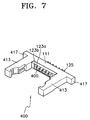
- the body 400 for the optical connector module according to the present invention may further have jaws 417 on extensions of its base 111.
- the jaws 417 are useful for accurate installation of the body on the jig, and simultaneously allows the jig to easily hold the body 400.
- the shape of the cover member is varied according to the shape of the body.
- the body for receiving both the connector and the holder to couple the optical fibers with the optical device is constructed to have an open structure without top and bottom plates, which reduces the thickness of the body.
- the cover member is opened downward.
- the optical connector module according to the present invention can be manufactured to be slim.
- the optical connector module according to the present invention can be adapted for high-speed signal reception and transmission to a device which requires such a slim optical connector module, for example, a display unit of notebook computers.
- the open configuration of the body with a binding space therein allows bonding operations after the combination of the holder with the body. If bonding operations can be carried out after insertion of the holder into the body, it is possible for a jig to hold the body, rather than the holder which is relatively smaller than the body, which facilitates bonding operations.
- guide grooves formed on the inner sides of the body can be used as a reference point for bonding of optical devices, so that the optical device can be accurately aligned with optical fibers, which also allows easy bonding operations.
Landscapes
- Physics & Mathematics (AREA)
- General Physics & Mathematics (AREA)
- Optics & Photonics (AREA)
- Optical Couplings Of Light Guides (AREA)
- Mechanical Coupling Of Light Guides (AREA)
Applications Claiming Priority (2)
| Application Number | Priority Date | Filing Date | Title |
|---|---|---|---|
| KR1543299 | 1999-04-29 | ||
| KR1019990015432A KR100677065B1 (ko) | 1999-04-29 | 1999-04-29 | 광커넥터 모듈 |
Publications (3)
| Publication Number | Publication Date |
|---|---|
| EP1048965A2 true EP1048965A2 (de) | 2000-11-02 |
| EP1048965A3 EP1048965A3 (de) | 2000-12-13 |
| EP1048965B1 EP1048965B1 (de) | 2008-01-30 |
Family
ID=19582913
Family Applications (1)
| Application Number | Title | Priority Date | Filing Date |
|---|---|---|---|
| EP00303643A Expired - Lifetime EP1048965B1 (de) | 1999-04-29 | 2000-04-28 | Optisches Verbindermodul |
Country Status (6)
| Country | Link |
|---|---|
| US (1) | US6386768B1 (de) |
| EP (1) | EP1048965B1 (de) |
| JP (1) | JP3636634B2 (de) |
| KR (1) | KR100677065B1 (de) |
| CN (1) | CN1166969C (de) |
| DE (1) | DE60037920T2 (de) |
Cited By (14)
| Publication number | Priority date | Publication date | Assignee | Title |
|---|---|---|---|---|
| DE10055683A1 (de) * | 2000-11-03 | 2002-05-29 | Infineon Technologies Ag | Vorrichtung zum Entriegeln eines in eine Aufnahmevorrichtung einsteckbaren elektronischen Bauelements |
| EP1244052A1 (de) * | 2001-03-21 | 2002-09-25 | Hewlett-Packard Company | System und Methode ein Kabel an die Oberfläche eines Bauteils anzuheften |
| DE10114143A1 (de) * | 2001-03-16 | 2002-10-02 | Infineon Technologies Ag | Emissionsarmes elektrisches Bauteil |
| US6612858B1 (en) | 2000-11-03 | 2003-09-02 | Infineon Technologies Ag | Device for unlocking an electronic component that is insertible into a receiving device |
| WO2006039184A3 (en) * | 2004-09-30 | 2006-06-01 | Intel Corp | Fiber optic communication assembly |
| WO2006039200A3 (en) * | 2004-09-30 | 2006-06-22 | Intel Corp | Optical transceiver module |
| WO2006039050A3 (en) * | 2004-09-30 | 2006-06-29 | Intel Corp | Apparatus for an electro-optical device connection |
| US7342841B2 (en) | 2004-12-21 | 2008-03-11 | Intel Corporation | Method, apparatus, and system for active refresh management |
| US7371014B2 (en) | 2006-08-21 | 2008-05-13 | Intel Corporation | Monolithic active optical cable assembly for data device applications and various connector types |
| US7452139B2 (en) | 2006-08-21 | 2008-11-18 | Intel Corporation | Aligning lens carriers and ferrules with alignment frames |
| US7660128B2 (en) | 2004-09-30 | 2010-02-09 | Emcore Corporation | Apparatus for electrical and optical interconnection |
| CN104516062A (zh) * | 2014-11-28 | 2015-04-15 | 中航光电科技股份有限公司 | 光纤插座模块及使用该光纤插座模块的集成插座 |
| EP2273570B1 (de) * | 2002-09-05 | 2019-08-07 | Nichia Corporation | Halbleitervorrichtung |
| EP4485027A1 (de) * | 2023-06-29 | 2025-01-01 | INTEL Corporation | Architektur und verfahren zur passiven aktiven optischen ausrichtung einer photonischen integrierten schaltung (pic) und einer faserarrayeinheit (fau) |
Families Citing this family (52)
| Publication number | Priority date | Publication date | Assignee | Title |
|---|---|---|---|---|
| JP2001042170A (ja) * | 1999-07-28 | 2001-02-16 | Canon Inc | 光配線装置、その駆動方法およびそれを用いた電子機器 |
| US6975663B2 (en) * | 2001-02-26 | 2005-12-13 | Ricoh Company, Ltd. | Surface-emission laser diode operable in the wavelength band of 1.1-7μm and optical telecommunication system using such a laser diode |
| KR100440948B1 (ko) * | 2000-02-24 | 2004-07-21 | 삼성전자주식회사 | 휴대용 pc와 도킹 스테이션의 광 접속장치 |
| JP2002064212A (ja) * | 2000-08-18 | 2002-02-28 | Sumitomo Electric Ind Ltd | 光受信モジュール |
| US7590159B2 (en) | 2001-02-26 | 2009-09-15 | Ricoh Company, Ltd. | Surface-emission laser diode operable in the wavelength band of 1.1-1.7 micrometers and optical telecommunication system using such a laser diode |
| US7040814B2 (en) * | 2001-10-15 | 2006-05-09 | The Furukawa Electric Co., Ltd. | Functional optical module |
| US6722791B2 (en) * | 2002-04-19 | 2004-04-20 | Hon Hai Precision Ind. Co., Ltd. | Multi-fiber ferrule |
| US6851868B2 (en) * | 2003-06-20 | 2005-02-08 | Japan Aviation Electronics Industry, Limited | Optical connector module |
| JP4619067B2 (ja) * | 2004-09-02 | 2011-01-26 | 株式会社アドバンテスト | 光モジュール用ソケット |
| US7575380B2 (en) | 2004-10-15 | 2009-08-18 | Emcore Corporation | Integrated optical fiber and electro-optical converter |
| JP3960330B2 (ja) * | 2004-11-12 | 2007-08-15 | セイコーエプソン株式会社 | 光デバイスの接続構造、光デバイス、電子機器 |
| JP4699155B2 (ja) * | 2005-09-29 | 2011-06-08 | 日本電信電話株式会社 | 光モジュール |
| US7905664B1 (en) * | 2008-09-25 | 2011-03-15 | Lockheed Martin Corporation | Input/output connector having an active electrical/optical communication component |
| US8307010B2 (en) * | 2008-09-26 | 2012-11-06 | Microsoft Corporation | Data feature tracking through hierarchical node sets |
| JP4891981B2 (ja) * | 2008-12-12 | 2012-03-07 | ホシデン株式会社 | 光配線モジュール |
| KR200471776Y1 (ko) | 2008-12-24 | 2014-03-12 | 대성전기공업 주식회사 | 차량용 커넥터 조립체 |
| US20100266245A1 (en) * | 2009-04-16 | 2010-10-21 | Hon Hai Precision Ind. Co., Ltd. | Fiber termination for fiber optic connection system |
| JP2011017985A (ja) * | 2009-07-10 | 2011-01-27 | Molex Inc | 光コネクタ組立体、光コネクタ組立体用のケーブル及び光コネクタ組立体用のプラグ |
| JP5290074B2 (ja) | 2009-07-13 | 2013-09-18 | モレックス インコーポレイテド | 光コネクタ |
| JP2011022198A (ja) | 2009-07-13 | 2011-02-03 | Molex Inc | 光コネクタ |
| EP2478597B1 (de) * | 2009-09-18 | 2020-07-01 | Intel Corporation | Kombinierte optische und elektrische schnittstelle |
| CN102313933B (zh) * | 2010-07-08 | 2015-07-01 | 鸿富锦精密工业(深圳)有限公司 | 光纤耦合连接器 |
| TWM449965U (zh) * | 2011-06-14 | 2013-04-01 | Molex Inc | 具有一體扣合機構的套管組件 |
| US8529140B2 (en) * | 2011-11-01 | 2013-09-10 | Avago Technologies General Ip (Singapore) Pte. Ltd. | Method and apparatus for use in a parallel optical communications system for passively aligning an optics module with optoelectronic devices of the parallel optical communications module |
| KR101292746B1 (ko) * | 2012-07-04 | 2013-08-02 | 한국몰렉스 주식회사 | 오프셋 타입 와이어 투 보드 커넥터 |
| US9383519B2 (en) * | 2012-12-07 | 2016-07-05 | Avago Technologies General Ip (Singapore) Pte. Ltd. | Optical communication module with fiber submount and latching optics assembly |
| CN103090303A (zh) * | 2013-01-08 | 2013-05-08 | 深圳市华星光电技术有限公司 | 背光模块 |
| US9188753B2 (en) * | 2013-03-12 | 2015-11-17 | Intel Corporation | Optical connector assembly |
| KR101443562B1 (ko) * | 2013-03-27 | 2014-11-03 | 옵티시스 주식회사 | 광 커넥터 |
| KR101477379B1 (ko) * | 2013-03-27 | 2014-12-29 | 엘에스엠트론 주식회사 | 광전 배선 모듈 |
| CN103293609B (zh) * | 2013-05-22 | 2015-05-20 | 武汉电信器件有限公司 | 一种模块锁扣卸载装置 |
| TWI521248B (zh) * | 2014-08-07 | 2016-02-11 | 光興國際股份有限公司 | 光學收發器 |
| CN105445869B (zh) | 2014-09-01 | 2017-08-11 | 富士康(昆山)电脑接插件有限公司 | 光模组 |
| US10114184B2 (en) | 2014-12-31 | 2018-10-30 | Ls Mtron Ltd. | Optical connector |
| KR102019740B1 (ko) * | 2014-12-31 | 2019-09-09 | 엘에스엠트론 주식회사 | 광 커넥터 |
| US9658409B2 (en) | 2015-03-03 | 2017-05-23 | Senko Advanced Components, Inc. | Optical fiber connector with changeable polarity |
| CN104808298B (zh) * | 2015-05-04 | 2016-08-24 | 长芯盛(武汉)科技有限公司 | 有源光纤耦合器件 |
| CN104991318A (zh) * | 2015-05-29 | 2015-10-21 | 长芯盛(武汉)科技有限公司 | 一种有源光缆光纤耦合器件 |
| KR102137704B1 (ko) * | 2015-06-17 | 2020-07-24 | 엘에스엠트론 주식회사 | 광전 하이브리드 커넥터 |
| JP2018091946A (ja) * | 2016-12-01 | 2018-06-14 | 日本航空電子工業株式会社 | 光モジュール |
| US10158194B2 (en) | 2016-01-15 | 2018-12-18 | Senko Advanced Components, Inc. | Narrow width adapters and connectors with spring loaded remote release |
| US9726830B1 (en) | 2016-06-28 | 2017-08-08 | Senko Advanced Components, Inc. | Connector and adapter system for two-fiber mechanical transfer type ferrule |
| JP6655523B2 (ja) * | 2016-10-26 | 2020-02-26 | 京セラ株式会社 | 光路変換部品 |
| US10228521B2 (en) | 2016-12-05 | 2019-03-12 | Senko Advanced Components, Inc. | Narrow width adapters and connectors with modular latching arm |
| US11333836B2 (en) | 2017-01-30 | 2022-05-17 | Senko Advanced Components, Inc. | Adapter for optical connectors |
| KR102322877B1 (ko) * | 2017-04-13 | 2021-11-04 | 엘에스엠트론 주식회사 | 광전 커넥터 |
| US11822133B2 (en) | 2017-07-14 | 2023-11-21 | Senko Advanced Components, Inc. | Ultra-small form factor optical connector and adapter |
| US12001064B2 (en) | 2017-07-14 | 2024-06-04 | Senko Advanced Components, Inc. | Small form factor fiber optic connector with multi-purpose boot |
| US10281668B2 (en) | 2017-07-14 | 2019-05-07 | Senko Advanced Components, Inc. | Ultra-small form factor optical connectors |
| US11579379B2 (en) | 2019-03-28 | 2023-02-14 | Senko Advanced Components, Inc. | Fiber optic adapter assembly |
| CN116325370A (zh) * | 2020-10-13 | 2023-06-23 | 申泰公司 | 用于高速数据传输的具有环形连接器的竖直插入互连系统 |
| KR102571515B1 (ko) * | 2022-10-18 | 2023-08-29 | 주식회사 엘티전자 | 광섬유 접속장치 및 그가 적용되는 디스플레이 장치 |
Family Cites Families (7)
| Publication number | Priority date | Publication date | Assignee | Title |
|---|---|---|---|---|
| US4233724A (en) * | 1979-04-20 | 1980-11-18 | Amp Incorporated | Method of accurately positioning fiber cables within ferrules |
| JPS58111008A (ja) * | 1981-12-24 | 1983-07-01 | Toshiba Corp | 光モジユ−ル |
| JPS62152378U (de) * | 1986-03-18 | 1987-09-26 | ||
| US5005939A (en) * | 1990-03-26 | 1991-04-09 | International Business Machines Corporation | Optoelectronic assembly |
| US5071219A (en) * | 1990-11-09 | 1991-12-10 | General Motors Corporation | Fiber optic connection system and method |
| US5168537A (en) * | 1991-06-28 | 1992-12-01 | Digital Equipment Corporation | Method and apparatus for coupling light between an optoelectronic device and a waveguide |
| JP2000121889A (ja) * | 1998-10-21 | 2000-04-28 | Nec Corp | 光モジュール及び該光モジュールの製造方法 |
-
1999
- 1999-04-29 KR KR1019990015432A patent/KR100677065B1/ko not_active Expired - Fee Related
-
2000
- 2000-04-28 EP EP00303643A patent/EP1048965B1/de not_active Expired - Lifetime
- 2000-04-28 JP JP2000131232A patent/JP3636634B2/ja not_active Expired - Fee Related
- 2000-04-28 DE DE60037920T patent/DE60037920T2/de not_active Expired - Fee Related
- 2000-04-29 CN CNB001192337A patent/CN1166969C/zh not_active Expired - Fee Related
- 2000-05-01 US US09/561,924 patent/US6386768B1/en not_active Expired - Fee Related
Cited By (23)
| Publication number | Priority date | Publication date | Assignee | Title |
|---|---|---|---|---|
| DE10055683A1 (de) * | 2000-11-03 | 2002-05-29 | Infineon Technologies Ag | Vorrichtung zum Entriegeln eines in eine Aufnahmevorrichtung einsteckbaren elektronischen Bauelements |
| US6612858B1 (en) | 2000-11-03 | 2003-09-02 | Infineon Technologies Ag | Device for unlocking an electronic component that is insertible into a receiving device |
| US6854997B2 (en) | 2000-11-03 | 2005-02-15 | Infineon Technologies Ag | Device for unlocking an electronic component that is insertible into a receiving device |
| DE10055683B4 (de) * | 2000-11-03 | 2006-05-11 | Infineon Technologies Ag | Vorrichtung zum Entriegeln eines in eine Aufnahmevorrichtung einsteckbaren elektronischen Bauelements |
| DE10114143A1 (de) * | 2001-03-16 | 2002-10-02 | Infineon Technologies Ag | Emissionsarmes elektrisches Bauteil |
| DE10114143C2 (de) * | 2001-03-16 | 2003-05-22 | Infineon Technologies Ag | opto-elektronisches Sende- und/oder Empfangsbauteil |
| EP1244052A1 (de) * | 2001-03-21 | 2002-09-25 | Hewlett-Packard Company | System und Methode ein Kabel an die Oberfläche eines Bauteils anzuheften |
| US6643225B2 (en) | 2001-03-21 | 2003-11-04 | Hewlett-Packard Development Company, L.P. | System and method for retaining a first part against a second part |
| EP2273570B1 (de) * | 2002-09-05 | 2019-08-07 | Nichia Corporation | Halbleitervorrichtung |
| WO2006039050A3 (en) * | 2004-09-30 | 2006-06-29 | Intel Corp | Apparatus for an electro-optical device connection |
| US7661886B2 (en) | 2004-09-30 | 2010-02-16 | Emcore Corporation | Apparatus for electro-optical device connection |
| US7352969B2 (en) | 2004-09-30 | 2008-04-01 | Intel Corporation | Fiber optic communication assembly |
| WO2006039200A3 (en) * | 2004-09-30 | 2006-06-22 | Intel Corp | Optical transceiver module |
| US7373031B2 (en) | 2004-09-30 | 2008-05-13 | Intel Corporation | Apparatus for an electro-optical device connection |
| WO2006039184A3 (en) * | 2004-09-30 | 2006-06-01 | Intel Corp | Fiber optic communication assembly |
| US7660128B2 (en) | 2004-09-30 | 2010-02-09 | Emcore Corporation | Apparatus for electrical and optical interconnection |
| US7342841B2 (en) | 2004-12-21 | 2008-03-11 | Intel Corporation | Method, apparatus, and system for active refresh management |
| US8289797B2 (en) | 2004-12-21 | 2012-10-16 | Intel Corporation | Method, apparatus, and system for active refresh management |
| US7371014B2 (en) | 2006-08-21 | 2008-05-13 | Intel Corporation | Monolithic active optical cable assembly for data device applications and various connector types |
| US7578623B2 (en) | 2006-08-21 | 2009-08-25 | Intel Corporation | Aligning lens carriers and ferrules with alignment frames |
| US7452139B2 (en) | 2006-08-21 | 2008-11-18 | Intel Corporation | Aligning lens carriers and ferrules with alignment frames |
| CN104516062A (zh) * | 2014-11-28 | 2015-04-15 | 中航光电科技股份有限公司 | 光纤插座模块及使用该光纤插座模块的集成插座 |
| EP4485027A1 (de) * | 2023-06-29 | 2025-01-01 | INTEL Corporation | Architektur und verfahren zur passiven aktiven optischen ausrichtung einer photonischen integrierten schaltung (pic) und einer faserarrayeinheit (fau) |
Also Published As
| Publication number | Publication date |
|---|---|
| EP1048965B1 (de) | 2008-01-30 |
| US6386768B1 (en) | 2002-05-14 |
| DE60037920D1 (de) | 2008-03-20 |
| DE60037920T2 (de) | 2009-02-05 |
| EP1048965A3 (de) | 2000-12-13 |
| JP2000321467A (ja) | 2000-11-24 |
| JP3636634B2 (ja) | 2005-04-06 |
| KR20000067536A (ko) | 2000-11-25 |
| CN1273367A (zh) | 2000-11-15 |
| CN1166969C (zh) | 2004-09-15 |
| KR100677065B1 (ko) | 2007-02-01 |
Similar Documents
| Publication | Publication Date | Title |
|---|---|---|
| EP1048965A2 (de) | Optischer Modul Verbinder | |
| US8414199B2 (en) | Optical connector and lens block connecting structure, and optical module | |
| EP1919041B1 (de) | Lampenfassung und Anzeigevorrichtung damit | |
| CN101176024B (zh) | 连接器座、带连接器座的光电转换器、光连接器固定结构、以及连接器座的组装方法 | |
| US8465213B2 (en) | Optical module | |
| US20070140643A1 (en) | Cable connector type transceiver module | |
| JP3455168B2 (ja) | レセプタクルモジュール | |
| JPH0922021A (ja) | 液晶表示装置 | |
| JP2009223063A (ja) | 光モジュール | |
| JP2007286553A (ja) | 電気光変換モジュール | |
| JP4543561B2 (ja) | 光モジュールの製造方法、及び光モジュール | |
| JP5246534B2 (ja) | 光モジュール | |
| CN101167005A (zh) | 光背板连接器、光电转换模块和光背板 | |
| TW401517B (en) | A light transmission module | |
| JP5352864B2 (ja) | 光コネクタとレンズブロックの接続構造、及び光モジュール | |
| JP5109087B2 (ja) | 光モジュール | |
| JP4867047B2 (ja) | 光モジュール | |
| JP2009053281A (ja) | 光モジュール | |
| JP2009198921A (ja) | 光モジュール | |
| JP2015032556A (ja) | 光コネクタ | |
| JP5246535B2 (ja) | 光モジュール | |
| JP5246537B2 (ja) | 光素子・電子部品実装ボード | |
| JP2009053276A (ja) | 光モジュール | |
| JP2004109324A (ja) | 光モジュール | |
| JP5223047B2 (ja) | 光モジュール |
Legal Events
| Date | Code | Title | Description |
|---|---|---|---|
| PUAI | Public reference made under article 153(3) epc to a published international application that has entered the european phase |
Free format text: ORIGINAL CODE: 0009012 |
|
| PUAL | Search report despatched |
Free format text: ORIGINAL CODE: 0009013 |
|
| 17P | Request for examination filed |
Effective date: 20000524 |
|
| AK | Designated contracting states |
Kind code of ref document: A2 Designated state(s): DE FR GB |
|
| AX | Request for extension of the european patent |
Free format text: AL;LT;LV;MK;RO;SI |
|
| AK | Designated contracting states |
Kind code of ref document: A3 Designated state(s): AT BE CH CY DE DK ES FI FR GB GR IE IT LI LU MC NL PT SE |
|
| AX | Request for extension of the european patent |
Free format text: AL;LT;LV;MK;RO;SI |
|
| AKX | Designation fees paid |
Free format text: DE FR GB |
|
| 17Q | First examination report despatched |
Effective date: 20051011 |
|
| GRAP | Despatch of communication of intention to grant a patent |
Free format text: ORIGINAL CODE: EPIDOSNIGR1 |
|
| GRAS | Grant fee paid |
Free format text: ORIGINAL CODE: EPIDOSNIGR3 |
|
| GRAA | (expected) grant |
Free format text: ORIGINAL CODE: 0009210 |
|
| AK | Designated contracting states |
Kind code of ref document: B1 Designated state(s): DE FR GB |
|
| REG | Reference to a national code |
Ref country code: GB Ref legal event code: FG4D |
|
| REF | Corresponds to: |
Ref document number: 60037920 Country of ref document: DE Date of ref document: 20080320 Kind code of ref document: P |
|
| PGFP | Annual fee paid to national office [announced via postgrant information from national office to epo] |
Ref country code: GB Payment date: 20080313 Year of fee payment: 9 |
|
| PGFP | Annual fee paid to national office [announced via postgrant information from national office to epo] |
Ref country code: FR Payment date: 20080313 Year of fee payment: 9 Ref country code: DE Payment date: 20080530 Year of fee payment: 9 |
|
| ET | Fr: translation filed | ||
| PLBE | No opposition filed within time limit |
Free format text: ORIGINAL CODE: 0009261 |
|
| STAA | Information on the status of an ep patent application or granted ep patent |
Free format text: STATUS: NO OPPOSITION FILED WITHIN TIME LIMIT |
|
| 26N | No opposition filed |
Effective date: 20081031 |
|
| GBPC | Gb: european patent ceased through non-payment of renewal fee |
Effective date: 20090428 |
|
| REG | Reference to a national code |
Ref country code: FR Ref legal event code: ST Effective date: 20091231 |
|
| PG25 | Lapsed in a contracting state [announced via postgrant information from national office to epo] |
Ref country code: DE Free format text: LAPSE BECAUSE OF NON-PAYMENT OF DUE FEES Effective date: 20091103 |
|
| PG25 | Lapsed in a contracting state [announced via postgrant information from national office to epo] |
Ref country code: GB Free format text: LAPSE BECAUSE OF NON-PAYMENT OF DUE FEES Effective date: 20090428 Ref country code: FR Free format text: LAPSE BECAUSE OF NON-PAYMENT OF DUE FEES Effective date: 20091222 |