EP1049852B1 - Frässystem und verfahren im bohrloch - Google Patents
Frässystem und verfahren im bohrloch Download PDFInfo
- Publication number
- EP1049852B1 EP1049852B1 EP99901718A EP99901718A EP1049852B1 EP 1049852 B1 EP1049852 B1 EP 1049852B1 EP 99901718 A EP99901718 A EP 99901718A EP 99901718 A EP99901718 A EP 99901718A EP 1049852 B1 EP1049852 B1 EP 1049852B1
- Authority
- EP
- European Patent Office
- Prior art keywords
- mill
- hook
- wellbore
- whipstock
- shoulder
- Prior art date
- Legal status (The legal status is an assumption and is not a legal conclusion. Google has not performed a legal analysis and makes no representation as to the accuracy of the status listed.)
- Expired - Lifetime
Links
- 238000000034 method Methods 0.000 title claims description 9
- 238000003801 milling Methods 0.000 title description 15
- 239000000463 material Substances 0.000 claims description 8
- 238000000926 separation method Methods 0.000 claims description 2
- 125000006850 spacer group Chemical group 0.000 claims description 2
- 238000005520 cutting process Methods 0.000 description 7
- 239000011159 matrix material Substances 0.000 description 5
- 238000005553 drilling Methods 0.000 description 2
- 239000012530 fluid Substances 0.000 description 2
- 238000004519 manufacturing process Methods 0.000 description 1
- 238000010008 shearing Methods 0.000 description 1
Images
Classifications
-
- E—FIXED CONSTRUCTIONS
- E21—EARTH OR ROCK DRILLING; MINING
- E21B—EARTH OR ROCK DRILLING; OBTAINING OIL, GAS, WATER, SOLUBLE OR MELTABLE MATERIALS OR A SLURRY OF MINERALS FROM WELLS
- E21B29/00—Cutting or destroying pipes, packers, plugs or wire lines, located in boreholes or wells, e.g. cutting of damaged pipes, of windows; Deforming of pipes in boreholes or wells; Reconditioning of well casings while in the ground
- E21B29/06—Cutting windows, e.g. directional window cutters for whipstock operations
Definitions
- This invention relates to a system and a method for lowering at least one member into a wellbore.
- Milling tools are used to cut out windows or pockets from a tubular, e.g. for directional drilling and sidetracking; and to remove materials downhole in a well bore, such as pipe, casing, casing liners, tubing, or jammed tools.
- the prior art discloses various types of milling or cutting tools provided for cutting or milling existing pipe or casing previously installed in a well. These tools have cutting blades or surfaces and are lowered into the well or casing and then rotated in a cutting operation. With certain tools, a suitable drilling fluid is pumped down a central bore of a tool for discharge adjacent or beneath the cutting blades. An upward flow of the discharged fluid in the annulus outside the tool removes cuttings or chips from the well resulting from the milling operation.
- Prior art sidetracking methods employ a variety of wellbore mills, including, but not limited to, well known starting mills and window mills.
- a whipstock deflects a mill laterally while it is being moved downwardly in a well during rotation of the mill to cut an elongated opening pocket, or window in well casing.
- Certain prior art well sidetracking operations which employ a whipstock also employ a variety of different mills and milling systems used in a certain sequence.
- This sequence of operation may require a plurality of "trips" into the wellbore.
- an anchor, slip mechanism, or an anchor-packer is set in a wellbore at a desired location.
- a whipstock-mill combination tool is then run into the wellbore by first properly orienting a stinger at the bottom of the tool with respect to a concave face of the tool's whipstock.
- a starting mill or a window mill is releasably secured at the top of the whips took, e.g. with a shearable member, e.g.
- This setting stud bears the entire load of whatever is connected beneath the lowermost mill.
- the tool is then lowered into the wellbore oriented and anchored.
- Putting weight down on the tool then shears the setting stud, freeing the lowermost mill, e.g. a window mill or a starting mill from the tool.
- the mill is diverted into the casing and the casing is milled in some cases as the pilot lug is milled off.
- the mill moves downwardly while contacting the concave portion and cuts an initial window in the casing. If a starting mill is the lowermost mill, it is then removed from the wellbore.
- a window mill e.g. on a flexible joint of drill pipe, is lowered into the wellbore and rotated to mill down from the initial window formed by the starting mill. Then additional mills may be used behind the window mill to lengthen and/or finish the casing window
- US-A-5,109,924 discloses a system for lowering a whipstock attached to a mill into a wellbore.
- a system for use with a wellbore comprising a mill and at least one member supported therefrom and intended for being lowered into the wellbore, characterised in that one of said mill and said at least one member is provided with a shoulder and the other of said mill and at least one member is provided with a hook, such that, in use, said shoulder and hook engage to inhibit separation of said mill and said at least one member.
- said system comprises a shear pin arranged between said mill and said at least one member.
- said system comprises a latch arranged between said mill and said at least one member.
- the latch is hydraulically actuable.
- said hook and said shoulder are disengagable by rotation of said mill.
- said hook is provided with a lip extension.
- said shoulder is formed on a lug.
- said lug is made from a millable material.
- mill comprises a starting mill, a window mill or both.
- said at least one member comprises a whipstook.
- said at least one member also comprises at least one of an anchor, a packer, anchor-packer, an orienting device, a plug, one or more tubulars, one or more spacers for repositioning said whipstock.
- a method for lowering at least one member into a wellbore using the system of the invention comprising the step of lowering said at least one member on a mill and disengaging said hook from said shoulder to detach the at least one member from said hook.
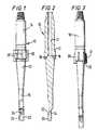
- FIG. 1 and 2 there is shown a starting mill 10 according to the present invention with a main body 12 having a top 14 and a bottom 16 with a flow bore 17 therethrough extending from the top 14 to exhaust ports 18.
- a lower tapered part of the mill 10 ends in a hook portion 20 that has a lip 22 sized and configured for positioning below a top lug 44 of a whipstock 40 so that the lug 44 can rest thereon, thereby allowing the whipstock 40 to hang from the hook portion 20.
- a hole 24 through the bottom 16 of the mill 10 permits a shear stud 42 to be arranged through the mill 10 with part projecting into a corresponding hole in lug 44.
- the mill 10 may include any known blade and/or milling matrix material to provide cutting action.
- a plurality of milling blades 30 are secured to or formed of the main body 12.
- the bladas are dressed with matrix milling material (e.g. KUTRITE (tm) material); with milling inserts; or with both - in any known pattern, array, or combination.
- matrix milling material e.g. KUTRITE (tm) material
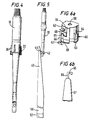
- Blades 30 are dressed with matrix miling material 31 and with inserts 32.
- Blades 30 are dressed with matrix milling material 33.
- FIG. 5 shows a starting mill (e.g. the mill 10) secured by a shear stud 42 to a lug 44 of a whipstock 40.
- Numeral 50 indicates schematically a whipstock anchor mechanism (e.g. anchor - hydraulically and/or mechanically settable, settable slip device, anchor-packer) and
- numeral 52 indicates schematically, one or more tubulars secured below the anchor mechanism.
- any mill, mill system, or mill-drill tool may have a hook portion as described above and be used with a whipstock as shown in Figure 5.
- Figure 6a shows a window mill 60 with a body 62 and a milling end 63. At least one hook recess 64 is formed in the body 62 providing a shoulder 69 and, in one aspect as shown there are a plurality of such recesses spaced-apart around the mill body 62. A corresponding top hook portion 65 of a lug 66 of a whipstock 67 is releasably held in he recess 64. In one aspect an hydraulically actuable latch 68 projects movably and outwardly over the top of the top hook portion to releasably maintain the top hook portion in the recess.
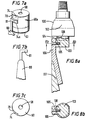
- Figure 7a shows a window mill 60a with a hook recess 74 providing a shoulder 74a, the hook recess 74 having a tapered end portion 70 so that mill rotation facilitates release of the top hook portion 81 of a whipstock 80 shown in Fig. 7b.
- Figures 8a and 8b show a mill 100 according to the present invention with a body 102 and a pilot end 103 having a support shoulder 104.
- a shear stud 105 extends through a top lug 106 of a whipstock 107 into the pilot end 103 of the mill 100.
- the support shoulder 104 underlies a projecting portion 108 of the top lug 106 and thereby supports the whipstock 107 (and anything connected therebeneath).
- the mill body and milling surfaces of the mill 100 and/or of the pilot end 103 may be dressed with any known matrix milling material and/or inserts in any known arrangement, combination, array or pattern by any known method.
Landscapes
- Life Sciences & Earth Sciences (AREA)
- Engineering & Computer Science (AREA)
- Geology (AREA)
- Mining & Mineral Resources (AREA)
- Physics & Mathematics (AREA)
- Environmental & Geological Engineering (AREA)
- Fluid Mechanics (AREA)
- General Life Sciences & Earth Sciences (AREA)
- Geochemistry & Mineralogy (AREA)
- Earth Drilling (AREA)
Claims (12)
- System zur Verwendung mit einem Bohrloch, wobei das System einen Fräser (10; 60; 60a; 100) und wenigstens ein von demselben gehaltenes und zum Absenken in das Bohrloch vorgesehenes Element (40; 67; 80; 107) umfaßt, dadurch gekennzeichnet, daß eines der Teile Fräser (10; 60; 60a; 100) und wenigstens ein Element (40; 67; 80; 107) mit einem Absatz (44; 69; 74a; 104) versehen ist und das andere der Teile Fräser (10; 60; 60a; 100) und wenigstens ein Element (40; 67; 80; 107) mit einem Haken (22; 65; 81; 108) versehen ist, wobei die Anordnung derart ist, daß bei der Verwendung der Absatz (44; 69; 74a; 104) und der Haken (20; 65; 81; 108) ineinandergreifen, um eine Trennung des Fräsers (10; 60; 60a; 100) und des wenigstens einen Elements (40; 67; 80; 107) zu hemmen.
- System nach Anspruch 1, bei dem das System einen Abscherbolzen (42) umfaßt, der zwischen dem Fräser (10; 60; 60a; 100) und dem wenigstens einen Element (40; 67; 80; 107) angeordnet ist.
- System nach Anspruch 1 oder 2, bei dem das System eine Fallklinke (68) umfaßt, die zwischen dem Fräser (10; 60; 60a; 100) und dem wenigstens einen Element (40; 67; 80; 107) angeordnet ist.
- System nach Anspruch 3, bei dem die Fallklinke (68) hydraulisch betätigt werden kann.
- System nach einem der vorhergehenden Ansprüche, bei dem der Haken (65; 81) und der Absatz (69; 74a) durch eine Drehung des Fräsers (60; 60a) außer Eingriff gebracht werden können.
- System nach einem der vorhergehenden Ansprüche, bei dem der Haken (65) mit einer Lippenerweiterung versehen ist.
- System nach einem der vorhergehenden Ansprüche, bei dem der Absatz (44; 108) auf einem Ansatz (44; 106) oder durch denselben gebildet wird.
- System nach Anspruch 7, bei dem der Ansatz (44; 106) aus einem fräsbaren Material hergestellt wird.
- System nach einem der vorhergehenden Ansprüche, bei dem der Fräser (10; 60; 60a; 100) einen Anlauffräser, einen Pensterfräser oder beides umfaßt.
- System nach einem der vorhergehenden Ansprüche, bei dem das wenigstens eine Element (40; 67; 80; 107) einen Ablenkkeil (40) umfaßt.
- System nach Anspruch 10, bei dem das wenigstens eine Element (40; 67; 80; 107) außerdem wenigstens eins der Teile Anker, Einfachschieber, Anker-Einfachschieber, Ausrichtungsvorrichtung, Stopfen, ein oder mehrere Rohrabschnitte, ein oder mehrere Abstandsstücke zum Repositionieren des Ablenkkeils (40) umfaßt.
- Verfahren zum Absenken wenigstens eines Elements (40; 67; 80; 107) in ein Bohrloch unter Verwendung des Systems nach einem der vorhergehenden Ansprüche, wobei das Verfahren den Schritt des Absenkens des wenigstens einen Elements (40; 67; 80; 107) auf einem Fräser (10; 60; 60a; 100) und des Außereingriffbringens des Hakens (22; 65; 81; 108) vom Absatz (44; 69; 74a; 104) umfaßt, um das wenigstens eine Element vom Haken zu lösen.
Applications Claiming Priority (3)
| Application Number | Priority Date | Filing Date | Title |
|---|---|---|---|
| US09/012,337 US6032740A (en) | 1998-01-23 | 1998-01-23 | Hook mill systems |
| US12337 | 1998-01-23 | ||
| PCT/GB1999/000078 WO1999037882A1 (en) | 1998-01-23 | 1999-01-25 | Milling system and method in a wellbore |
Publications (2)
| Publication Number | Publication Date |
|---|---|
| EP1049852A1 EP1049852A1 (de) | 2000-11-08 |
| EP1049852B1 true EP1049852B1 (de) | 2003-04-02 |
Family
ID=21754490
Family Applications (1)
| Application Number | Title | Priority Date | Filing Date |
|---|---|---|---|
| EP99901718A Expired - Lifetime EP1049852B1 (de) | 1998-01-23 | 1999-01-25 | Frässystem und verfahren im bohrloch |
Country Status (6)
| Country | Link |
|---|---|
| US (1) | US6032740A (de) |
| EP (1) | EP1049852B1 (de) |
| AU (1) | AU2172499A (de) |
| CA (1) | CA2319260A1 (de) |
| DE (1) | DE69906485T2 (de) |
| WO (1) | WO1999037882A1 (de) |
Families Citing this family (16)
| Publication number | Priority date | Publication date | Assignee | Title |
|---|---|---|---|---|
| US6715567B2 (en) * | 2001-05-02 | 2004-04-06 | Weatherford/Lamb, Inc. | Apparatus and method for forming a pilot hole in a formation |
| US8069920B2 (en) * | 2009-04-02 | 2011-12-06 | Knight Information Systems, L.L.C. | Lateral well locator and reentry apparatus and method |
| CA2830721C (en) | 2011-03-01 | 2016-06-28 | Smith International, Inc. | High performance wellbore departure and drilling system |
| CA2832296C (en) * | 2011-04-05 | 2016-05-24 | Smith International Inc. | System and method for coupling a drill bit to a whipstock |
| WO2012142543A2 (en) | 2011-04-15 | 2012-10-18 | Smith International, Inc. | System and method for coupling an impregnated drill bit to a whipstock |
| US9835011B2 (en) | 2013-01-08 | 2017-12-05 | Knight Information Systems, Llc | Multi-window lateral well locator/reentry apparatus and method |
| US10871034B2 (en) * | 2016-02-26 | 2020-12-22 | Halliburton Energy Services, Inc. | Whipstock assembly with a support member |
| US11136843B1 (en) | 2020-03-25 | 2021-10-05 | Baker Hughes Oilfield Operations Llc | Casing exit anchor with redundant activation system |
| US11414943B2 (en) | 2020-03-25 | 2022-08-16 | Baker Hughes Oilfield Operations Llc | On-demand hydrostatic/hydraulic trigger system |
| US11162315B2 (en) | 2020-03-25 | 2021-11-02 | Baker Hughes Oilfield Operations Llc | Window mill and whipstock connector for a resource exploration and recovery system |
| US11421496B1 (en) * | 2020-03-25 | 2022-08-23 | Baker Hughes Oilfield Operations Llc | Mill to whipstock connection system |
| US11162314B2 (en) | 2020-03-25 | 2021-11-02 | Baker Hughes Oilfield Operations Llc | Casing exit anchor with redundant activation system |
| US11131159B1 (en) | 2020-03-25 | 2021-09-28 | Baker Hughes Oilfield Operations Llc | Casing exit anchor with redundant setting system |
| US11702888B2 (en) | 2020-03-25 | 2023-07-18 | Baker Hughes Oilfield Operations Llc | Window mill and whipstock connector for a resource exploration and recovery system |
| US12241311B2 (en) | 2023-06-12 | 2025-03-04 | Halliburton Energy Services, Inc. | Splined/grooved 2 piece bit assembly |
| US12331607B2 (en) * | 2023-06-12 | 2025-06-17 | Halliburton Energy Services, Inc. | Downhole tool including related lug slots and lugs for coupling a milling tool and whipstock assembly |
Family Cites Families (29)
| Publication number | Priority date | Publication date | Assignee | Title |
|---|---|---|---|---|
| US2807440A (en) * | 1953-08-10 | 1957-09-24 | J E Hill | Directional window cutter for whipstocks |
| US2882015A (en) * | 1957-06-10 | 1959-04-14 | J E Hill | Directional window cutter for whipstocks |
| US3908759A (en) * | 1974-05-22 | 1975-09-30 | Standard Oil Co | Sidetracking tool |
| US4796709A (en) * | 1986-01-06 | 1989-01-10 | Tri-State Oil Tool Industries, Inc. | Milling tool for cutting well casing |
| US5038859A (en) * | 1988-04-15 | 1991-08-13 | Tri-State Oil Tools, Inc. | Cutting tool for removing man-made members from well bore |
| US4938291A (en) * | 1986-01-06 | 1990-07-03 | Lynde Gerald D | Cutting tool for cutting well casing |
| US4978260A (en) * | 1986-01-06 | 1990-12-18 | Tri-State Oil Tools, Inc. | Cutting tool for removing materials from well bore |
| US5014778A (en) * | 1986-01-06 | 1991-05-14 | Tri-State Oil Tools, Inc. | Milling tool for cutting well casing |
| US4717290A (en) * | 1986-12-17 | 1988-01-05 | Homco International, Inc. | Milling tool |
| DE3942438A1 (de) * | 1989-12-22 | 1991-07-11 | Eastman Christensen Co | Vorrichtung zum bohren einer neben- oder ablenkbohrung eines insbesondere verrohrten bohrlochs |
| GB9003047D0 (en) * | 1990-02-10 | 1990-04-11 | Tri State Oil Tool Uk | Insert type window mill |
| GB9120298D0 (en) * | 1991-09-24 | 1991-11-06 | Homco International Inc | Casing cutting and retrieving tool |
| US5341873A (en) * | 1992-09-16 | 1994-08-30 | Weatherford U.S., Inc. | Method and apparatus for deviated drilling |
| DE4395361T1 (de) * | 1992-10-19 | 1994-11-10 | Baker Hughes Inc | Wiederausbaubares Richtkeilsystem |
| US5720349A (en) * | 1995-10-12 | 1998-02-24 | Weatherford U.S., Inc. | Starting mill and operations |
| US5429187A (en) * | 1994-03-18 | 1995-07-04 | Weatherford U.S., Inc. | Milling tool and operations |
| US5425417A (en) * | 1993-09-10 | 1995-06-20 | Weatherford U.S., Inc. | Wellbore tool setting system |
| US5531271A (en) * | 1993-09-10 | 1996-07-02 | Weatherford Us, Inc. | Whipstock side support |
| US5727629A (en) * | 1996-01-24 | 1998-03-17 | Weatherford/Lamb, Inc. | Wellbore milling guide and method |
| US5425419A (en) * | 1994-02-25 | 1995-06-20 | Sieber; Bobby G. | Whipstock apparatus and methods of use |
| US5431220A (en) * | 1994-03-24 | 1995-07-11 | Smith International, Inc. | Whipstock starter mill assembly |
| US5443129A (en) * | 1994-07-22 | 1995-08-22 | Smith International, Inc. | Apparatus and method for orienting and setting a hydraulically-actuatable tool in a borehole |
| US5535822A (en) * | 1994-09-08 | 1996-07-16 | Enterra Corporation | Apparatus for retrieving whipstock |
| US5676206A (en) * | 1995-09-14 | 1997-10-14 | Baker Hughes Incorporated | Window-cutting system for downhole tubulars |
| US5678634A (en) * | 1995-10-17 | 1997-10-21 | Baker Hughes Incorporated | Method and apparatus for retrieving a whipstock |
| US5771972A (en) * | 1996-05-03 | 1998-06-30 | Smith International, Inc., | One trip milling system |
| US5816324A (en) * | 1996-05-03 | 1998-10-06 | Smith International, Inc. | Whipstock accelerator ramp |
| US5806596A (en) * | 1996-11-26 | 1998-09-15 | Baker Hughes Incorporated | One-trip whipstock setting and squeezing method |
| US5832997A (en) * | 1996-12-05 | 1998-11-10 | Halliburton Energy Services, Inc. | Retrievable milling guide anchor apparatus and associated methods |
-
1998
- 1998-01-23 US US09/012,337 patent/US6032740A/en not_active Expired - Lifetime
-
1999
- 1999-01-25 EP EP99901718A patent/EP1049852B1/de not_active Expired - Lifetime
- 1999-01-25 WO PCT/GB1999/000078 patent/WO1999037882A1/en not_active Ceased
- 1999-01-25 AU AU21724/99A patent/AU2172499A/en not_active Abandoned
- 1999-01-25 CA CA002319260A patent/CA2319260A1/en not_active Abandoned
- 1999-01-25 DE DE69906485T patent/DE69906485T2/de not_active Expired - Fee Related
Also Published As
| Publication number | Publication date |
|---|---|
| DE69906485D1 (de) | 2003-05-08 |
| CA2319260A1 (en) | 1999-07-29 |
| DE69906485T2 (de) | 2004-02-12 |
| EP1049852A1 (de) | 2000-11-08 |
| US6032740A (en) | 2000-03-07 |
| AU2172499A (en) | 1999-08-09 |
| WO1999037882A1 (en) | 1999-07-29 |
Similar Documents
| Publication | Publication Date | Title |
|---|---|---|
| EP1049852B1 (de) | Frässystem und verfahren im bohrloch | |
| CA2262106C (en) | Apparatus and method for milling a hole in casing | |
| US5887668A (en) | Wellbore milling-- drilling | |
| US6612383B2 (en) | Method and apparatus for milling well casing and drilling formation | |
| AU710673B2 (en) | Single trip whipstock assembly | |
| EP0960260B1 (de) | Werkzeug zum herstellen einer öffnung in einem rohr in einem bohrloch | |
| US8739900B2 (en) | System and method for coupling a drill bit to a whipstock | |
| EP1815102B1 (de) | Einmaldurchlauffrässystem | |
| EP0815345B1 (de) | Fräswerkzeug, ablenkkeil, frässystem und verfahren zum erstellen eines fensters in einem rohr | |
| US5584350A (en) | Wellbore sidetracking methods | |
| EP0888490B1 (de) | Fräswerkzeug zum fräsen in bohrlöchern | |
| EP1222357B1 (de) | Ein-marsch frässystem | |
| US20260078638A1 (en) | Whipstock for use with a mill bit including varying material removal rates | |
| CA3047252A1 (en) | Fixed cutter completions bit | |
| US20250179877A1 (en) | Cutting element including one or more asymmetric relief surfaces | |
| US20250179878A1 (en) | Cutting element including two or more shaped cutting features, each having a convex and inwardly/downwardly angled shape |
Legal Events
| Date | Code | Title | Description |
|---|---|---|---|
| PUAI | Public reference made under article 153(3) epc to a published international application that has entered the european phase |
Free format text: ORIGINAL CODE: 0009012 |
|
| 17P | Request for examination filed |
Effective date: 20000714 |
|
| AK | Designated contracting states |
Kind code of ref document: A1 Designated state(s): DE FR GB IT NL |
|
| 17Q | First examination report despatched |
Effective date: 20010517 |
|
| GRAG | Despatch of communication of intention to grant |
Free format text: ORIGINAL CODE: EPIDOS AGRA |
|
| GRAG | Despatch of communication of intention to grant |
Free format text: ORIGINAL CODE: EPIDOS AGRA |
|
| GRAH | Despatch of communication of intention to grant a patent |
Free format text: ORIGINAL CODE: EPIDOS IGRA |
|
| GRAH | Despatch of communication of intention to grant a patent |
Free format text: ORIGINAL CODE: EPIDOS IGRA |
|
| GRAA | (expected) grant |
Free format text: ORIGINAL CODE: 0009210 |
|
| AK | Designated contracting states |
Designated state(s): DE FR GB IT NL |
|
| PG25 | Lapsed in a contracting state [announced via postgrant information from national office to epo] |
Ref country code: IT Free format text: LAPSE BECAUSE OF FAILURE TO SUBMIT A TRANSLATION OF THE DESCRIPTION OR TO PAY THE FEE WITHIN THE PRE;WARNING: LAPSES OF ITALIAN PATENTS WITH EFFECTIVE DATE BEFORE 2007 MAY HAVE OCCURRED AT ANY TIME BEFORE 2007. THE CORRECT EFFECTIVE DATE MAY BE DIFFERENT FROM THE ONE RECORDED.SCRIBED TIME-LIMIT Effective date: 20030402 |
|
| REG | Reference to a national code |
Ref country code: GB Ref legal event code: FG4D |
|
| REF | Corresponds to: |
Ref document number: 69906485 Country of ref document: DE Date of ref document: 20030508 Kind code of ref document: P |
|
| ET | Fr: translation filed | ||
| PLBE | No opposition filed within time limit |
Free format text: ORIGINAL CODE: 0009261 |
|
| STAA | Information on the status of an ep patent application or granted ep patent |
Free format text: STATUS: NO OPPOSITION FILED WITHIN TIME LIMIT |
|
| 26N | No opposition filed |
Effective date: 20040105 |
|
| PG25 | Lapsed in a contracting state [announced via postgrant information from national office to epo] |
Ref country code: NL Free format text: LAPSE BECAUSE OF NON-PAYMENT OF DUE FEES Effective date: 20040801 |
|
| PG25 | Lapsed in a contracting state [announced via postgrant information from national office to epo] |
Ref country code: DE Free format text: LAPSE BECAUSE OF NON-PAYMENT OF DUE FEES Effective date: 20040803 |
|
| PG25 | Lapsed in a contracting state [announced via postgrant information from national office to epo] |
Ref country code: FR Free format text: LAPSE BECAUSE OF NON-PAYMENT OF DUE FEES Effective date: 20040930 |
|
| NLV4 | Nl: lapsed or anulled due to non-payment of the annual fee |
Effective date: 20040801 |
|
| REG | Reference to a national code |
Ref country code: FR Ref legal event code: ST |
|
| REG | Reference to a national code |
Ref country code: GB Ref legal event code: 732E Free format text: REGISTERED BETWEEN 20151022 AND 20151028 |
|
| PGFP | Annual fee paid to national office [announced via postgrant information from national office to epo] |
Ref country code: GB Payment date: 20180124 Year of fee payment: 20 |
|
| REG | Reference to a national code |
Ref country code: GB Ref legal event code: PE20 Expiry date: 20190124 |
|
| PG25 | Lapsed in a contracting state [announced via postgrant information from national office to epo] |
Ref country code: GB Free format text: LAPSE BECAUSE OF EXPIRATION OF PROTECTION Effective date: 20190124 |