EP1050244A2 - Verbindungselement für Möbelgestelle - Google Patents
Verbindungselement für Möbelgestelle Download PDFInfo
- Publication number
- EP1050244A2 EP1050244A2 EP00103699A EP00103699A EP1050244A2 EP 1050244 A2 EP1050244 A2 EP 1050244A2 EP 00103699 A EP00103699 A EP 00103699A EP 00103699 A EP00103699 A EP 00103699A EP 1050244 A2 EP1050244 A2 EP 1050244A2
- Authority
- EP
- European Patent Office
- Prior art keywords
- joint
- relative
- extensions
- adapter
- adapter means
- Prior art date
- Legal status (The legal status is an assumption and is not a legal conclusion. Google has not performed a legal analysis and makes no representation as to the accuracy of the status listed.)
- Granted
Links
- 230000013011 mating Effects 0.000 claims abstract description 16
- 239000002184 metal Substances 0.000 claims description 5
- 230000002596 correlated effect Effects 0.000 claims description 2
- 238000003754 machining Methods 0.000 description 3
- 230000008878 coupling Effects 0.000 description 2
- 238000010168 coupling process Methods 0.000 description 2
- 238000005859 coupling reaction Methods 0.000 description 2
- 230000000694 effects Effects 0.000 description 2
- 238000004519 manufacturing process Methods 0.000 description 2
- 239000000463 material Substances 0.000 description 2
- 230000035515 penetration Effects 0.000 description 2
- 230000000750 progressive effect Effects 0.000 description 2
- 239000007787 solid Substances 0.000 description 2
- 238000007792 addition Methods 0.000 description 1
- 239000000956 alloy Substances 0.000 description 1
- 229910045601 alloy Inorganic materials 0.000 description 1
- 238000013459 approach Methods 0.000 description 1
- 230000015572 biosynthetic process Effects 0.000 description 1
- 230000001419 dependent effect Effects 0.000 description 1
- 239000011888 foil Substances 0.000 description 1
- 230000005923 long-lasting effect Effects 0.000 description 1
- 239000000203 mixture Substances 0.000 description 1
- 238000012986 modification Methods 0.000 description 1
- 230000004048 modification Effects 0.000 description 1
- 230000002028 premature Effects 0.000 description 1
- 238000002360 preparation method Methods 0.000 description 1
- 230000002787 reinforcement Effects 0.000 description 1
- 230000003014 reinforcing effect Effects 0.000 description 1
Images


Classifications
-
- F—MECHANICAL ENGINEERING; LIGHTING; HEATING; WEAPONS; BLASTING
- F16—ENGINEERING ELEMENTS AND UNITS; GENERAL MEASURES FOR PRODUCING AND MAINTAINING EFFECTIVE FUNCTIONING OF MACHINES OR INSTALLATIONS; THERMAL INSULATION IN GENERAL
- F16B—DEVICES FOR FASTENING OR SECURING CONSTRUCTIONAL ELEMENTS OR MACHINE PARTS TOGETHER, e.g. NAILS, BOLTS, CIRCLIPS, CLAMPS, CLIPS OR WEDGES; JOINTS OR JOINTING
- F16B12/00—Jointing of furniture or the like, e.g. hidden from exterior
- F16B12/44—Leg joints; Corner joints
-
- A—HUMAN NECESSITIES
- A47—FURNITURE; DOMESTIC ARTICLES OR APPLIANCES; COFFEE MILLS; SPICE MILLS; SUCTION CLEANERS IN GENERAL
- A47B—TABLES; DESKS; OFFICE FURNITURE; CABINETS; DRAWERS; GENERAL DETAILS OF FURNITURE
- A47B13/00—Details of tables or desks
- A47B13/02—Underframes
-
- A—HUMAN NECESSITIES
- A47—FURNITURE; DOMESTIC ARTICLES OR APPLIANCES; COFFEE MILLS; SPICE MILLS; SUCTION CLEANERS IN GENERAL
- A47B—TABLES; DESKS; OFFICE FURNITURE; CABINETS; DRAWERS; GENERAL DETAILS OF FURNITURE
- A47B47/00—Cabinets, racks or shelf units, characterised by features related to dismountability or building-up from elements
- A47B47/0008—Three-dimensional corner connectors, the legs thereof being received within hollow, elongated frame members
-
- F—MECHANICAL ENGINEERING; LIGHTING; HEATING; WEAPONS; BLASTING
- F16—ENGINEERING ELEMENTS AND UNITS; GENERAL MEASURES FOR PRODUCING AND MAINTAINING EFFECTIVE FUNCTIONING OF MACHINES OR INSTALLATIONS; THERMAL INSULATION IN GENERAL
- F16B—DEVICES FOR FASTENING OR SECURING CONSTRUCTIONAL ELEMENTS OR MACHINE PARTS TOGETHER, e.g. NAILS, BOLTS, CIRCLIPS, CLAMPS, CLIPS OR WEDGES; JOINTS OR JOINTING
- F16B12/00—Jointing of furniture or the like, e.g. hidden from exterior
- F16B12/40—Joints for furniture tubing
-
- A—HUMAN NECESSITIES
- A47—FURNITURE; DOMESTIC ARTICLES OR APPLIANCES; COFFEE MILLS; SPICE MILLS; SUCTION CLEANERS IN GENERAL
- A47B—TABLES; DESKS; OFFICE FURNITURE; CABINETS; DRAWERS; GENERAL DETAILS OF FURNITURE
- A47B2230/00—Furniture jointing; Furniture with such jointing
- A47B2230/03—Nodal three-dimensional corner pieces for desks
Definitions
- This invention concerns an assembly joint for furniture frames as set forth in the main claim.
- the invention refers to a joint used to assemble frames comprising tubular elements associated to each other and defining the bearing structure of furniture such as tables, desks, work-benches, sinks, shelves or similar.
- the state of the art includes different types of joints for furniture frames comprising tubular elements made of metal or plastic, by means of which the tubular elements are assembled.
- the joints allow to connect together, normally at 90°, two or more tubular elements, constituting the legs or supports for the plane surfaces of furniture, arranged in a line and/or at an angle.
- the joints differ from each other not only in how the tubular elements are connected and in how said elements are constrained (mortised, screwed, etc.), but also according to the type, and particularly the section, of the tubular elements for which they are used.
- the same joint can usually be used only for a single type of tubular element (round, square, rectangular, etc.), and therefore it is necessary to prepare various different joints even within the same line of furniture which uses tubular elements of different types.
- the tubular elements have to be subjected to specific machining in correspondence with the ends so as to make them suitable to be connected to the relative joints for the furniture to be assembled.
- Such machining entails additional production costs and makes it necessary to prepare tubular elements of a specific length for each piece of furniture to be made; this prevents the tubular elements from being cut to size in the event that this operation is necessary during the assembly step or even at subsequent times.
- This document describes a joint comprising a main body with three wings arranged orthogonally with respect to each other; respective tubular elements constituting the frame of the piece of furniture are able to be anchored thereon.
- the wings are conical in shape, narrowing towards the outside of the main body; each one is suitable to cooperate with a conical assembly element, opposite and specular thereto.
- an expansion bushing consisting of a plurality of clamping wedges shaped as a double cone; the wedges are connected to each other by means of connection ribs.
- connection rib of the wedges is subject to considerable loads during the expansion step and the clamping of the tube, and therefore it is easily subject to premature wear and breakage.
- connection element for tubular structures wherein there are connection arms with a square section; the conical end is able to cooperate with expansion locking elements equipped with mating angled surfaces.
- This solution has a very limited clamping stability, and may cause troublesome play and looseness, because of the extremely limited coupling surface between the joint and the surface of the clamping elements.
- the purpose of the invention is to achieve a joint for furniture frames which will allow to achieve a safe and stable assembly of tubular elements, even with a different section.
- Another purpose of the invention is to achieve a joint which is economical to make and practical to use, which will allow to use tubular elements of a standardized type and simply cut to size, without needing to do any preparatory machining.
- a further purpose of the invention is to achieve a joint consisting of an extremely limited number of components, characterized in that it is very solid, subject to limited wear, extremely easy to assemble/dis-assemble, versatile and that there is substantially no limit to its use.
- the joint according to the invention comprises a main body with at least two extensions shaped like a truncated cone or a truncated pyramid and converging towards the outside of the main body.
- the extensions are able to cooperate with respective expanding adapter means, of the inter-changeable type, with an outer shape mating with the tubular elements which are to be employed and an inner shape mating with the truncated cone or truncated pyramid extensions.
- each of the adapter means is able to be inserted and clamped through interference inside the respective tubular elements to be connected to the joint and defines an axial cavity inside which one of the extensions with which the joint is equipped is able to be inserted and clamped.
- said axial cavity has a length correlated to that of the relative extension so that, in the assembled position, the extensions are entirely contained inside the relative adapter means.
- the truncated pyramid extensions have a square or rectangular base.
- the adapter means are able to be attached definitively to the respective extensions by means of screw elements or similar, arranged substantially axially along the relative extensions; the axis coincides with the axis of the tube to be assembled.
- the adapter means are able to couple in a snug fit with the relative extensions.
- each of the adapter means consists of a plurality of longitudinal shaped profiles, constrained elastically together and cooperating centrally with a traction plate, made at least temporally solid with the shaped profiles so as to constitute substantially a single piece therewith; each of the shaped profiles defines an angular portion of the axial cavity.
- the rear ends of the shaped profiles are shaped so as to define an elastic seating to contain and retain the plate, which can easily be removed once the adapter means has been extracted from the relative tube.
- the traction plate has a central, threaded hole, and it functions substantially as a nut to allow the adapter element to be screwed to the main body of the joint.
- the progressive screwing of the plate which draws the relative adapter means towards the main body of the joint, causes the shaped profiles to slide on the truncated pyramid surfaces of the extensions of the joint; this causes the shaped profiles to progressively expand towards the outside and to press against the inner wall of the tube.
- the adapter means are pre-assembled on the relative extensions of the main body of the joint, with a partial penetration of the extensions inside the relative axial cavities, and the tubular elements which are to be assembled are inserted onto the adapter means.
- the adapter means are constrained through interference to the inner walls of the tubular elements.
- the traction plate has a lateral play inside the relative housing seating when the adapter means is not clamped by the tube, and performs a function of reciprocal centering and positioning of the shaped profiles; it ensures that the radial expansion of the adapter means inside the relative tubular element occurs in a perfectly parallel manner along the whole longitudinal extension thereof.
- tubular elements are therefore stably associated with the joint and it is substantially impossible to disassociate them therefrom, unless the adapter means are removed or at least partly unscrewed.
- the invention allows to assemble tubular elements of different sections simply by replacing the adapter means.
- the adapter means are advantageously made of plastic, even though it comes within the field of the invention to make them in metal, alloy or other appropriate material.
- the reference number 10 denotes the joint for furniture frames 11 comprising a plurality of tubular elements 12 made of metal or plastic and assembled together.
- the joint 10 allows to assemble two or more tubular elements 12 of any section whatsoever, arranged either at an angle or in a line, either horizontal or vertical, normally at a reciprocal angle of 90°.
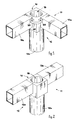
- Fig. 1 shows the example of a joint 10 with which two tubular elements with a rectangular section 12a are assembled, horizontal and arranged at a right angle, defining for example the supports of the plane surface of a table or a shelf, and a tubular element with a round section 12b, vertical and constituting for example a leg or an upright.
- the joint 10 shown in Fig. 2 allows to assemble in line two horizontal tubular elements with a rectangular section 12a, and a vertical round tubular element 12b.
- the joint 10 shown in a partly exploded view in Fig. 3 (the left portion of the joint is exploded while the right portion has the tube 12 assembled), comprises a main body 13, substantially cubic or parallelepiped in shape, provided in correspondence with its two faces with two lateral extensions 14 (of which only one is visible in the Figure) and a lower extension 15.
- the lateral extensions 14 are arranged orthogonal to each other on a substantially horizontal plane and are shaped like a truncated pyramid with a rectangular section.
- the lateral extensions 14 are able to be coupled with respective adapter elements 16 (of which only one is shown), which allow tubular elements with a rectangular section 12a to be clamped thereon.
- the lower extension 15 is substantially vertical, shaped like a truncated pyramid with a square section and is able to be coupled with an adapter element 17 which allows a tubular element 12b with a round section to be clamped thereon.
- the adapter elements 16, 17 have an inner shape mating with that of the extensions 14, 15 onto which they are inserted, and an outer shape mating with that of the relative tubular elements 12a, 12b.
- the extensions 14, 15 axially include respective through holes 14a, 15a communicating with a cavity 18 made on the main body 13 and open upwards.
- each of the two holes 14a has a wider part 114a defining a circumferential edge 30; in correspondence with the end of the hole 15a facing the cavity 18, on the contrary, there is in this case a ridge 31.
- the main body 13 also has a pair of through holes 29, communicating at one end with the cavity 18 and at the other end with the outside, aligned with the through holes 14a of the lateral extensions 14.
- a corner bracket 32 On the inner corner of the main body 13 there is a corner bracket 32 in a single piece therewith, equipped with through holes 33, which serves to facilitate the positioning and attachment of a plane associated above the joint 10; the bracket 32 also functions as a structural reinforcement.
- Each of the two adapter elements 16 comprises four longitudinal profiles 19, substantially identical, arranged in corner positions around a square or rectangular central plate 22, which functions as a traction nut; the profiles 19 are also reciprocally brought together or distanced by means of blocks or foils made of an at least partly elastic and/or yielding material.
- the blocks consist of arch-shaped bridges 21, able to elastically connect the profiles 19 two by two, and to permit a controlled elastic expansion.
- the front ends of the profiles 19 are shaped as teeth and, in their entirety, define a housing seating 23 for the plate 22.
- the teeth have a front edge 19c of a certain thickness which extends beyond the plate 22 and has a reinforcing and stiffening function, since the plate 22 is affected by the stresses deriving from the clamping of the tubular elements 12 to the joint 10.
- the adapter elements 16 are made of plastic, so as to have greater elasticity which will encourage expansion during the assembly step and a better grip on the inner wall of the tubes 12, whereas the plate 22 is made of metal.
- the plate 22 is made in a single piece with the profiles 19.
- the positioning of the plate 22 in the seating 23 defined between the profiles 19 is possible because the profiles 19 can be reciprocally moved elastically, thanks to the hinge function performed by the bridges 21, and to the presence of the undercuts 119 which allow to bring the profiles 19 closer together.
- Each profile 19 substantially comprises a rear extension 19a, with a right-angled longitudinal development, an intermediate plate 19b and a protruding front edge 19c (Fig. 4a).
- each profile 19 is able to cooperate, due to its having the same shape, with a respective edge 14b of the lateral extension 14 during the assembly step.
- the central plate 22 is constrained with a certain lateral play in the housing seating 23 made between the intermediate plates 19b and the front edges 19c of the profiles 19.
- the plate 22 has an axial threaded hole 24, of a diameter mating with the hole 14a of the lateral extension 14.
- the profiles 19, and in particular their extensions 19a define internally an axial cavity 20, shaped like a truncated pyramid, mating with the lateral extension 14, inside which the latter is able to be inserted.
- the profiles 19 also define an outer transverse section of the adapter element 16 with a shape mating with the inner section of the tubular element 12a.
- the profiles 19 are able to expand progressively outwards, distancing themselves from each other in correspondence with the rear extensions 19a, thanks to the bridges 21, but remaining in any case associated with the central plate 22, which is actually locked between the edges 19c which close towards each other when the extensions expand.
- the adapter element 17 comprises four profiles 27 associated radially, in a similar way to the profiles 19 of the adapter element 16, around a central plate (not shown here) which has an axial threaded hole with a diameter mating with the through hole 15a of the lower extension 15.
- the profiles 27, like the similar profiles 19, define an axial cavity 28, of a shape mating with that of the lower extension 15; the profiles 27 also have a circular outer development defining an outer conformation of the adapter element 17 mating with the inner section of the tubular element 12b.
- the adapter elements 16 and 17 are inserted and pre-assembled on the relative extensions 14 and 15, and then the tubular elements 12a and 12b are inserted on the relative adapter elements 16 and 17.
- the adapter elements 16 are assembled on the relative lateral extensions 14, with a first, slight radial expansion due to the truncated pyramid shape of the latter.
- the length of the axial cavity 20 substantially coincides with the length of the extension 14 so that, in the assembled position, the whole inner surface of the adapter element 16 is coupled with the relative outer surface of the relative extension.
- tubular elements 12a are inserted on the elements 16 and are clamped thereon due to the interference of the inner walls 112a with the profiles 19.
- tubular elements 12a are definitively assembled by inserting a screw 25 through the hole 29 into the through hole 14a and screwing it into the threaded hole 24 of the plate 22 (Fig. 4b) which substantially functions as a nut.
- the screw 25 abuts against the circumferential edge 30 with the head 25a, and hence its progressive tightening causes the adapter/tubular element combination to exert a traction effect on the lateral extension 14, and therefore a further radial expansion of the adapter element 16 caused as it approaches the main body 13 and consequently the relative profiles 19 expand due to the truncated pyramid shape of the relative extension 14.
- the tubular element 12b is assembled in the same way, coupling the adapter element 17 to the lower extension 15 and using a screw 26 inserted, through the cavity 18, into the through hole 15a with the head 26a abutting on the ridge 31.
- the joint 10 allows to assemble tubular elements 12 of different section in correspondence with the extensions 14, 15 by replacing only the adapter elements 16, 17 by adapter elements with the same axial cavity, but with an outer conformation mating with the section of the specific tubular element 12 to be assembled.
- the extensions 14 and 15 may have a converging polyhedral conformation different from the truncated pyramid with a rectangular section, cooperating with adapter elements composed of a different number of profiles.
- the joint 10 may be completed with covering elements which can be associated in a snug fit with the cavity 18 and/or the faces of the main body 13 which have the holes 29.
Landscapes
- Engineering & Computer Science (AREA)
- General Engineering & Computer Science (AREA)
- Mechanical Engineering (AREA)
- Furniture Connections (AREA)
- Mutual Connection Of Rods And Tubes (AREA)
- Supports Or Holders For Household Use (AREA)
Applications Claiming Priority (2)
| Application Number | Priority Date | Filing Date | Title |
|---|---|---|---|
| ITUD990041 | 1999-02-23 | ||
| IT1999UD000041A IT1310997B1 (it) | 1999-02-23 | 1999-02-23 | Giunto di assemblaggio per telai di mobili. |
Publications (3)
| Publication Number | Publication Date |
|---|---|
| EP1050244A2 true EP1050244A2 (de) | 2000-11-08 |
| EP1050244A3 EP1050244A3 (de) | 2000-11-15 |
| EP1050244B1 EP1050244B1 (de) | 2004-09-29 |
Family
ID=11422884
Family Applications (1)
| Application Number | Title | Priority Date | Filing Date |
|---|---|---|---|
| EP00103699A Expired - Lifetime EP1050244B1 (de) | 1999-02-23 | 2000-02-22 | Verbindungselement für Möbelgestelle |
Country Status (5)
| Country | Link |
|---|---|
| EP (1) | EP1050244B1 (de) |
| AT (1) | ATE277545T1 (de) |
| DE (1) | DE60014228T2 (de) |
| ES (1) | ES2229979T3 (de) |
| IT (1) | IT1310997B1 (de) |
Cited By (23)
| Publication number | Priority date | Publication date | Assignee | Title |
|---|---|---|---|---|
| US4521510A (en) * | 1982-06-30 | 1985-06-04 | E. I. Du Pont De Nemours And Company | Hybridoma cell lines and monoclonal antibodies to theophylline |
| US4524025A (en) * | 1982-06-30 | 1985-06-18 | E. I. Du Pont De Nemours And Company | Hybridoma cell lines and monoclonal antibodies to theophylline |
| DE20105551U1 (de) * | 2001-03-29 | 2002-08-08 | Eisfink Max Maier GmbH & Co. KG, 71636 Ludwigsburg | Knotenelement für Gestellkonstruktion |
| WO2002099292A1 (en) * | 2001-06-07 | 2002-12-12 | Ideassociates (Iom) Limited | A connector device for releasable connecting of tube or rod members |
| EP1447023A1 (de) * | 2003-02-12 | 2004-08-18 | Robur International srl | Halterungsvorrichtung zur Befestigung eines länglichen Elements mit einer ebenen Fläche |
| EP1559921A1 (de) * | 2004-01-27 | 2005-08-03 | Formenti & Giovenzana S.p.A. | Verbindung für die Zusammensetzung von drei-dimensionale Strukture |
| RU2293891C2 (ru) * | 2002-01-31 | 2007-02-20 | Сеан Компани С.П.А. | Соединительное устройство для трубчатых элементов |
| EP1892366A1 (de) * | 2006-08-25 | 2008-02-27 | Tesa AG | Rahmen, bevorzugter Weise Fliegengitterrahmen |
| EP2138069A3 (de) * | 2008-06-19 | 2010-01-20 | Sedus Systems GmbH | Bausatz zur Erzeugung eines Mehrfunktionen-Schreib- oder -Arbeitstisches |
| GB2463126A (en) * | 2008-09-05 | 2010-03-10 | William Andrew Makinson | Box beam jointing system |
| EP1722112A3 (de) * | 2005-04-28 | 2011-04-06 | VS Vereinigte Spezialmöbelfabriken GmbH & Co. KG | Leichtbau-Verbindungsvorrichtung |
| ITUD20100187A1 (it) * | 2010-10-15 | 2012-04-16 | Sinetica Ind S R L | Giunto di collegamento per elementi tubolari di una struttura componibile e relativo procedimento di montaggio |
| DE102010042955A1 (de) * | 2010-10-26 | 2012-06-06 | Sedus Stoll Ag | Vorrichtung zum Befestigen eines rohrförmigen ersten Möbelbauteils an einem zweiten Möbelbauteil, Knotenbauteil für ein Möbel, Möbel sowie Verfahren |
| ITMI20110602A1 (it) * | 2011-04-11 | 2012-10-12 | Muzzin S P A | Tavolo con aggancio gambe semplificato |
| KR200463947Y1 (ko) * | 2010-05-13 | 2012-12-06 | 김명환 | 조립식 가구의 지지프레임 |
| TWI496704B (de) * | 2013-02-05 | 2015-08-21 | ||
| CN107165910A (zh) * | 2017-06-23 | 2017-09-15 | 震旦(中国)有限公司 | 一种桌子的横梁与桌脚连接结构及桌子 |
| EP3506440A1 (de) * | 2017-12-27 | 2019-07-03 | Quanta Computer Inc. | Modulares schrankdesign |
| KR102058675B1 (ko) * | 2019-01-09 | 2019-12-24 | (주)아모스아인스가구 | 테이블 지지각에 대한 프레임연결구의 이중 조립구조 |
| KR102146338B1 (ko) * | 2020-02-17 | 2020-08-20 | 유연순 | 비노출형 체결구조를 갖는 테이블 프레임 조립체 |
| US20220120309A1 (en) * | 2020-10-20 | 2022-04-21 | Fortress Iron, Lp | Internal connector system for structural members |
| WO2024100204A1 (en) * | 2022-11-11 | 2024-05-16 | Mladen Pintur | Furniture structure made from metal |
| US12060712B2 (en) | 2020-10-20 | 2024-08-13 | Fortress Iron, Lp | Structural post with internal connector system |
Families Citing this family (2)
| Publication number | Priority date | Publication date | Assignee | Title |
|---|---|---|---|---|
| ES2311377B1 (es) * | 2006-10-25 | 2009-12-02 | Akaba, S.A. | Armazon-bastidor para mesas de configuracion variable. |
| IT202100009431A1 (it) * | 2021-04-14 | 2022-10-14 | Emmeallaenne S R L | Giunto di connessione |
Citations (2)
| Publication number | Priority date | Publication date | Assignee | Title |
|---|---|---|---|---|
| EP0403852A2 (de) | 1989-06-22 | 1990-12-27 | Siemens Nixdorf Informationssysteme Aktiengesellschaft | Eckverbinder für aus Profilrohren bestehende Gestelle |
| GB2264517A (en) | 1992-01-31 | 1993-09-01 | Ergotrak Building Systems Ltd | Connector for e.g. building modules |
Family Cites Families (11)
| Publication number | Priority date | Publication date | Assignee | Title |
|---|---|---|---|---|
| NL137879C (de) * | 1962-03-05 | 1978-06-15 | ||
| GB1264534A (de) * | 1966-09-06 | 1972-02-23 | ||
| FR1544860A (fr) * | 1967-09-29 | 1968-11-08 | Dispositif d'assemblage d'éléments profilés, tubulaires notamment pour la fabrication de meubles | |
| CH564930A5 (en) * | 1972-11-02 | 1975-08-15 | Mueller Walter Innenarchitekte | Joint for furniture tubular members - clamps tubes by expanding rubber bush between conical washers |
| DE2339337C2 (de) * | 1973-08-03 | 1975-07-31 | Veyhl-Produktion, 7261 Zwerenberg | Verbindung für die Rohre von Rahmengestellen |
| FR2247926A5 (en) * | 1973-10-15 | 1975-05-09 | Somnier Daniel | Junction piece for three table frame tubes - has circular tapering translation nuts expanding arms within tube ends |
| FR2562176B3 (fr) * | 1984-03-29 | 1986-07-18 | Applic Plastiques Equip Ele | Dispositif pour l'assemblage de barres profilees tubulaires, notamment pour la construction d'armoires electriques ou d'armoires industrielles |
| US4921370A (en) * | 1988-06-27 | 1990-05-01 | Hirsh Company | Tube connector |
| FR2642799B1 (fr) * | 1989-02-07 | 1991-05-03 | Merlin Gerin | Armoire pour appareillage electrique a ossature assemblee par vissage |
| DE9308677U1 (de) * | 1993-06-10 | 1993-10-14 | Hestex Systems B.V., Apeldoorn | Befestigungselement zum lösbaren Verbinden eines Mehrkantrohres, vorzugsweise eines Vierkantrohres |
| US5556218A (en) * | 1995-04-14 | 1996-09-17 | Homer; John L. | Tubing connector |
-
1999
- 1999-02-23 IT IT1999UD000041A patent/IT1310997B1/it active
-
2000
- 2000-02-22 DE DE60014228T patent/DE60014228T2/de not_active Expired - Fee Related
- 2000-02-22 EP EP00103699A patent/EP1050244B1/de not_active Expired - Lifetime
- 2000-02-22 ES ES00103699T patent/ES2229979T3/es not_active Expired - Lifetime
- 2000-02-22 AT AT00103699T patent/ATE277545T1/de not_active IP Right Cessation
Patent Citations (2)
| Publication number | Priority date | Publication date | Assignee | Title |
|---|---|---|---|---|
| EP0403852A2 (de) | 1989-06-22 | 1990-12-27 | Siemens Nixdorf Informationssysteme Aktiengesellschaft | Eckverbinder für aus Profilrohren bestehende Gestelle |
| GB2264517A (en) | 1992-01-31 | 1993-09-01 | Ergotrak Building Systems Ltd | Connector for e.g. building modules |
Cited By (30)
| Publication number | Priority date | Publication date | Assignee | Title |
|---|---|---|---|---|
| US4524025A (en) * | 1982-06-30 | 1985-06-18 | E. I. Du Pont De Nemours And Company | Hybridoma cell lines and monoclonal antibodies to theophylline |
| US4521510A (en) * | 1982-06-30 | 1985-06-04 | E. I. Du Pont De Nemours And Company | Hybridoma cell lines and monoclonal antibodies to theophylline |
| DE20105551U1 (de) * | 2001-03-29 | 2002-08-08 | Eisfink Max Maier GmbH & Co. KG, 71636 Ludwigsburg | Knotenelement für Gestellkonstruktion |
| WO2002099292A1 (en) * | 2001-06-07 | 2002-12-12 | Ideassociates (Iom) Limited | A connector device for releasable connecting of tube or rod members |
| RU2293891C2 (ru) * | 2002-01-31 | 2007-02-20 | Сеан Компани С.П.А. | Соединительное устройство для трубчатых элементов |
| EP1447023A1 (de) * | 2003-02-12 | 2004-08-18 | Robur International srl | Halterungsvorrichtung zur Befestigung eines länglichen Elements mit einer ebenen Fläche |
| EP1559921A1 (de) * | 2004-01-27 | 2005-08-03 | Formenti & Giovenzana S.p.A. | Verbindung für die Zusammensetzung von drei-dimensionale Strukture |
| EP1722112A3 (de) * | 2005-04-28 | 2011-04-06 | VS Vereinigte Spezialmöbelfabriken GmbH & Co. KG | Leichtbau-Verbindungsvorrichtung |
| EP1892366A1 (de) * | 2006-08-25 | 2008-02-27 | Tesa AG | Rahmen, bevorzugter Weise Fliegengitterrahmen |
| EP2138069A3 (de) * | 2008-06-19 | 2010-01-20 | Sedus Systems GmbH | Bausatz zur Erzeugung eines Mehrfunktionen-Schreib- oder -Arbeitstisches |
| GB2463255A (en) * | 2008-09-05 | 2010-03-10 | William Andrew Makinson | Box beam jointing system |
| GB2463126A (en) * | 2008-09-05 | 2010-03-10 | William Andrew Makinson | Box beam jointing system |
| GB2463126B (en) * | 2008-09-05 | 2012-07-25 | William Andrew Makinson | Box beam jointing system |
| KR200463947Y1 (ko) * | 2010-05-13 | 2012-12-06 | 김명환 | 조립식 가구의 지지프레임 |
| ITUD20100187A1 (it) * | 2010-10-15 | 2012-04-16 | Sinetica Ind S R L | Giunto di collegamento per elementi tubolari di una struttura componibile e relativo procedimento di montaggio |
| EP2441349A1 (de) * | 2010-10-15 | 2012-04-18 | Sinetica Industries Srl | Verbindungsanschluss für rohrförmige Elemente einer modularen Struktur und zugehöriges Anordnungsverfahren |
| DE102010042955A1 (de) * | 2010-10-26 | 2012-06-06 | Sedus Stoll Ag | Vorrichtung zum Befestigen eines rohrförmigen ersten Möbelbauteils an einem zweiten Möbelbauteil, Knotenbauteil für ein Möbel, Möbel sowie Verfahren |
| DE102010042955B4 (de) * | 2010-10-26 | 2017-02-16 | Sedus Stoll Ag | Vorrichtung zum Befestigen eines rohrförmigen ersten Möbelbauteils an einem zweiten Möbelbauteil, Knotenbauteil für ein Möbel, Möbel sowie Verfahren |
| ITMI20110602A1 (it) * | 2011-04-11 | 2012-10-12 | Muzzin S P A | Tavolo con aggancio gambe semplificato |
| TWI496704B (de) * | 2013-02-05 | 2015-08-21 | ||
| CN107165910A (zh) * | 2017-06-23 | 2017-09-15 | 震旦(中国)有限公司 | 一种桌子的横梁与桌脚连接结构及桌子 |
| CN109982541B (zh) * | 2017-12-27 | 2021-03-16 | 广达电脑股份有限公司 | 机柜结构及其框架元件组件 |
| CN109982541A (zh) * | 2017-12-27 | 2019-07-05 | 广达电脑股份有限公司 | 机柜结构及其框架元件组件 |
| US10610013B2 (en) | 2017-12-27 | 2020-04-07 | Quanta Computer Inc. | Modular cabinet design |
| EP3506440A1 (de) * | 2017-12-27 | 2019-07-03 | Quanta Computer Inc. | Modulares schrankdesign |
| KR102058675B1 (ko) * | 2019-01-09 | 2019-12-24 | (주)아모스아인스가구 | 테이블 지지각에 대한 프레임연결구의 이중 조립구조 |
| KR102146338B1 (ko) * | 2020-02-17 | 2020-08-20 | 유연순 | 비노출형 체결구조를 갖는 테이블 프레임 조립체 |
| US20220120309A1 (en) * | 2020-10-20 | 2022-04-21 | Fortress Iron, Lp | Internal connector system for structural members |
| US12060712B2 (en) | 2020-10-20 | 2024-08-13 | Fortress Iron, Lp | Structural post with internal connector system |
| WO2024100204A1 (en) * | 2022-11-11 | 2024-05-16 | Mladen Pintur | Furniture structure made from metal |
Also Published As
| Publication number | Publication date |
|---|---|
| IT1310997B1 (it) | 2002-02-27 |
| DE60014228D1 (de) | 2004-11-04 |
| ITUD990041A1 (it) | 2000-08-23 |
| DE60014228T2 (de) | 2005-10-06 |
| EP1050244B1 (de) | 2004-09-29 |
| EP1050244A3 (de) | 2000-11-15 |
| ES2229979T3 (es) | 2005-05-01 |
| ATE277545T1 (de) | 2004-10-15 |
Similar Documents
| Publication | Publication Date | Title |
|---|---|---|
| EP1050244B1 (de) | Verbindungselement für Möbelgestelle | |
| US4616953A (en) | Knock down pivot fastener | |
| US4501512A (en) | Furniture article with compression hub for joining radial members | |
| US7223045B2 (en) | Device and method for detachably connecting abutting structural parts and tie member for use to form said device | |
| US2926941A (en) | Device for connecting members together | |
| US3901612A (en) | Releaseable joint | |
| DE69301237T2 (de) | Möbel mit rohrförmigem untergestell | |
| EP1135616B1 (de) | T-verbindung zweier profilstäbe | |
| US6808334B2 (en) | Connecting system for modular furniture structures | |
| US5348414A (en) | Connection system for two structural component parts constructed as pipe or rod and/or nodal elements | |
| WO2019182457A1 (en) | A structural support system and a method for providing a node section for use in a structural support system | |
| US4726705A (en) | Knock down pivot fastener | |
| EP0477707B1 (de) | Verbindungseinrichtung für ein insbesondere rohrförmiges Bauteil | |
| GB2185798A (en) | Composite tubular structures | |
| DE4422211C1 (de) | Bausatz, insbesondere für Busse | |
| US20040101358A1 (en) | Joint for modular frames of furnishing elements such as tables, desks, shelves or the like | |
| EP1615528B1 (de) | Verbindungselement und gestellsystem | |
| JP4046259B2 (ja) | 支保工用の部材連結装置 | |
| DE3507157C2 (de) | Standmöbelsatz | |
| DE60117277T2 (de) | Verbindungsvorrichtung zum lösbaren verbinden von rohr- oder stangengliedern | |
| KR102058671B1 (ko) | 가구용 프레임 연결 고정구 | |
| CN210068660U (zh) | 板料连接组件及板料连接结构 | |
| DE10030919A1 (de) | Zerlegbarer Profilrahmen sowie Tischsystem mit einem solchen Profilrohrrahmen | |
| KR200398021Y1 (ko) | 가구용 금속 부재의 직결볼트 구조 | |
| EP1612433A1 (de) | Anschlussverbindung für ein Möbelgestell |
Legal Events
| Date | Code | Title | Description |
|---|---|---|---|
| PUAI | Public reference made under article 153(3) epc to a published international application that has entered the european phase |
Free format text: ORIGINAL CODE: 0009012 |
|
| PUAL | Search report despatched |
Free format text: ORIGINAL CODE: 0009013 |
|
| AK | Designated contracting states |
Kind code of ref document: A2 Designated state(s): AT BE CH CY DE DK ES FI FR GB GR IE IT LI LU MC NL PT SE |
|
| AX | Request for extension of the european patent |
Free format text: AL;LT;LV;MK;RO;SI |
|
| AK | Designated contracting states |
Kind code of ref document: A3 Designated state(s): AT BE CH CY DE DK ES FI FR GB GR IE IT LI LU MC NL PT SE |
|
| AX | Request for extension of the european patent |
Free format text: AL;LT;LV;MK;RO;SI |
|
| RIC1 | Information provided on ipc code assigned before grant |
Free format text: 7A 47B 47/00 A, 7F 16B 12/40 B, 7F 16B 12/44 B, 7A 47B 13/02 B |
|
| 17P | Request for examination filed |
Effective date: 20010226 |
|
| AKX | Designation fees paid |
Free format text: AT BE CH CY DE DK ES FI FR GB GR IE IT LI LU MC NL PT SE |
|
| 17Q | First examination report despatched |
Effective date: 20020909 |
|
| GRAP | Despatch of communication of intention to grant a patent |
Free format text: ORIGINAL CODE: EPIDOSNIGR1 |
|
| GRAS | Grant fee paid |
Free format text: ORIGINAL CODE: EPIDOSNIGR3 |
|
| GRAA | (expected) grant |
Free format text: ORIGINAL CODE: 0009210 |
|
| AK | Designated contracting states |
Kind code of ref document: B1 Designated state(s): AT BE CH CY DE DK ES FI FR GB GR IE IT LI LU MC NL PT SE |
|
| PG25 | Lapsed in a contracting state [announced via postgrant information from national office to epo] |
Ref country code: NL Free format text: LAPSE BECAUSE OF FAILURE TO SUBMIT A TRANSLATION OF THE DESCRIPTION OR TO PAY THE FEE WITHIN THE PRESCRIBED TIME-LIMIT Effective date: 20040929 Ref country code: LI Free format text: LAPSE BECAUSE OF FAILURE TO SUBMIT A TRANSLATION OF THE DESCRIPTION OR TO PAY THE FEE WITHIN THE PRESCRIBED TIME-LIMIT Effective date: 20040929 Ref country code: FI Free format text: LAPSE BECAUSE OF FAILURE TO SUBMIT A TRANSLATION OF THE DESCRIPTION OR TO PAY THE FEE WITHIN THE PRESCRIBED TIME-LIMIT Effective date: 20040929 Ref country code: CH Free format text: LAPSE BECAUSE OF FAILURE TO SUBMIT A TRANSLATION OF THE DESCRIPTION OR TO PAY THE FEE WITHIN THE PRESCRIBED TIME-LIMIT Effective date: 20040929 Ref country code: BE Free format text: LAPSE BECAUSE OF FAILURE TO SUBMIT A TRANSLATION OF THE DESCRIPTION OR TO PAY THE FEE WITHIN THE PRESCRIBED TIME-LIMIT Effective date: 20040929 Ref country code: AT Free format text: LAPSE BECAUSE OF FAILURE TO SUBMIT A TRANSLATION OF THE DESCRIPTION OR TO PAY THE FEE WITHIN THE PRESCRIBED TIME-LIMIT Effective date: 20040929 |
|
| REG | Reference to a national code |
Ref country code: GB Ref legal event code: FG4D |
|
| REG | Reference to a national code |
Ref country code: CH Ref legal event code: EP |
|
| REG | Reference to a national code |
Ref country code: IE Ref legal event code: FG4D |
|
| REF | Corresponds to: |
Ref document number: 60014228 Country of ref document: DE Date of ref document: 20041104 Kind code of ref document: P |
|
| PG25 | Lapsed in a contracting state [announced via postgrant information from national office to epo] |
Ref country code: SE Free format text: LAPSE BECAUSE OF FAILURE TO SUBMIT A TRANSLATION OF THE DESCRIPTION OR TO PAY THE FEE WITHIN THE PRESCRIBED TIME-LIMIT Effective date: 20041229 Ref country code: GR Free format text: LAPSE BECAUSE OF FAILURE TO SUBMIT A TRANSLATION OF THE DESCRIPTION OR TO PAY THE FEE WITHIN THE PRESCRIBED TIME-LIMIT Effective date: 20041229 Ref country code: DK Free format text: LAPSE BECAUSE OF FAILURE TO SUBMIT A TRANSLATION OF THE DESCRIPTION OR TO PAY THE FEE WITHIN THE PRESCRIBED TIME-LIMIT Effective date: 20041229 |
|
| PGFP | Annual fee paid to national office [announced via postgrant information from national office to epo] |
Ref country code: DE Payment date: 20050204 Year of fee payment: 6 |
|
| PGFP | Annual fee paid to national office [announced via postgrant information from national office to epo] |
Ref country code: ES Payment date: 20050208 Year of fee payment: 6 |
|
| PGFP | Annual fee paid to national office [announced via postgrant information from national office to epo] |
Ref country code: FR Payment date: 20050209 Year of fee payment: 6 |
|
| PG25 | Lapsed in a contracting state [announced via postgrant information from national office to epo] |
Ref country code: LU Free format text: LAPSE BECAUSE OF NON-PAYMENT OF DUE FEES Effective date: 20050222 Ref country code: IT Free format text: LAPSE BECAUSE OF NON-PAYMENT OF DUE FEES Effective date: 20050222 Ref country code: GB Free format text: LAPSE BECAUSE OF NON-PAYMENT OF DUE FEES Effective date: 20050222 Ref country code: CY Free format text: LAPSE BECAUSE OF FAILURE TO SUBMIT A TRANSLATION OF THE DESCRIPTION OR TO PAY THE FEE WITHIN THE PRESCRIBED TIME-LIMIT Effective date: 20050222 |
|
| PG25 | Lapsed in a contracting state [announced via postgrant information from national office to epo] |
Ref country code: MC Free format text: LAPSE BECAUSE OF NON-PAYMENT OF DUE FEES Effective date: 20050228 |
|
| NLV1 | Nl: lapsed or annulled due to failure to fulfill the requirements of art. 29p and 29m of the patents act | ||
| REG | Reference to a national code |
Ref country code: CH Ref legal event code: PL |
|
| REG | Reference to a national code |
Ref country code: ES Ref legal event code: FG2A Ref document number: 2229979 Country of ref document: ES Kind code of ref document: T3 |
|
| ET | Fr: translation filed | ||
| PLBE | No opposition filed within time limit |
Free format text: ORIGINAL CODE: 0009261 |
|
| STAA | Information on the status of an ep patent application or granted ep patent |
Free format text: STATUS: NO OPPOSITION FILED WITHIN TIME LIMIT |
|
| 26N | No opposition filed |
Effective date: 20050630 |
|
| GBPC | Gb: european patent ceased through non-payment of renewal fee |
Effective date: 20050222 |
|
| REG | Reference to a national code |
Ref country code: IE Ref legal event code: MM4A |
|
| PG25 | Lapsed in a contracting state [announced via postgrant information from national office to epo] |
Ref country code: ES Free format text: LAPSE BECAUSE OF NON-PAYMENT OF DUE FEES Effective date: 20060223 |
|
| PG25 | Lapsed in a contracting state [announced via postgrant information from national office to epo] |
Ref country code: DE Free format text: LAPSE BECAUSE OF NON-PAYMENT OF DUE FEES Effective date: 20060901 |
|
| REG | Reference to a national code |
Ref country code: FR Ref legal event code: ST Effective date: 20061031 |
|
| REG | Reference to a national code |
Ref country code: ES Ref legal event code: FD2A Effective date: 20060223 |
|
| PG25 | Lapsed in a contracting state [announced via postgrant information from national office to epo] |
Ref country code: PT Free format text: LAPSE BECAUSE OF NON-PAYMENT OF DUE FEES Effective date: 20050228 |
|
| PG25 | Lapsed in a contracting state [announced via postgrant information from national office to epo] |
Ref country code: FR Free format text: LAPSE BECAUSE OF NON-PAYMENT OF DUE FEES Effective date: 20060228 |