EP1050247A1 - Armoire - Google Patents
Armoire Download PDFInfo
- Publication number
- EP1050247A1 EP1050247A1 EP99810392A EP99810392A EP1050247A1 EP 1050247 A1 EP1050247 A1 EP 1050247A1 EP 99810392 A EP99810392 A EP 99810392A EP 99810392 A EP99810392 A EP 99810392A EP 1050247 A1 EP1050247 A1 EP 1050247A1
- Authority
- EP
- European Patent Office
- Prior art keywords
- frame
- cabinet element
- cabinet
- attached
- side wall
- Prior art date
- Legal status (The legal status is an assumption and is not a legal conclusion. Google has not performed a legal analysis and makes no representation as to the accuracy of the status listed.)
- Withdrawn
Links
- 238000005096 rolling process Methods 0.000 claims description 3
- 238000006073 displacement reaction Methods 0.000 claims description 2
- 238000004519 manufacturing process Methods 0.000 description 1
Images







Classifications
-
- A—HUMAN NECESSITIES
- A47—FURNITURE; DOMESTIC ARTICLES OR APPLIANCES; COFFEE MILLS; SPICE MILLS; SUCTION CLEANERS IN GENERAL
- A47B—TABLES; DESKS; OFFICE FURNITURE; CABINETS; DRAWERS; GENERAL DETAILS OF FURNITURE
- A47B81/00—Cabinets or racks specially adapted for other particular purposes, e.g. for storing guns or skis
- A47B81/002—Corner cabinets; Cabinets designed for being placed in a corner or a niche
Definitions
- the present invention relates to a cabinet element, in particular an upper cabinet of a kitchen device that is essentially one right-angled corner forms, according to the preamble of the claim 1.
- Kitchen facilities usually consist of base cabinets, which are provided with a cover, in which sink and hot plates are recessed, and in addition to a large storage area also work surfaces offer for kitchen users.
- These base cabinets are designed that they not only go from wall to wall in kitchens, but also around them Corners are guided.
- the corner area in the corresponding base cabinet is only difficult to access because the two rear sides of the corresponding angle Cabinet element are hidden by the walls of the kitchen while the two front sides through the angular continuation elements of the base cabinet are covered.
- Like access to corner elements of base cabinets can be guaranteed, for example EP-A-0 441 919.
- the object of the present invention is now a Cupboard element, in particular an upper cupboard of a kitchen device, which forms an essentially right - angled corner so that the Space utilization is optimal and good accessibility is achieved.
- the depth of the cabinet element can be fully exploited accessibility is achieved by pivoting around the vertical Optimal axis, especially on the rear part of the first storage compartments.
- a carriage which is provided with a vertical frame, which other storage compartments can be attached to.
- This car can be used in the Corner area of the cabinet element are pushed back, which in the front Area of the cabinet element in which the access is located, Space is created for the inserted first frame with the first Storage compartments. If the first frame with the first storage compartments from the Cabinet element is pulled out, the trolley with the other storage compartments be moved into the area of access to the cabinet element. This will make the other storage compartments accessible in the locked Condition of the cabinet element in the rear area of the cabinet element are optimally achieved.
- Another advantageous embodiment of the invention consists in that the car is equipped with four wheels, of which the two to the rear wall the cabinet element arranged in a parallel to the rear wall extending in the cabinet element preferably attached to the floor element Guide rail are guided longitudinally. The other two roles are free-rolling supported on the bottom element of the cabinet element. This will optimal guidance of the car achieved, the space required by this Leadership can be used, kept to a minimum.
- Another advantageous embodiment of the invention consists in that the vertical frame is attached to the carriage so that it is against the rear Side wall directed and parallel to this side wall. With this Arrangement, the depth of the cabinet element can be fully exploited.
- a guideway which is related to is stationary on the vertical axis, and along which a guide element is guided, in the end region of the first frame facing away from the door element attached to this.
- the guideway is shaped so that when Pull the first frame out of the cabinet element first a little Swiveling of the first frame around the vertical axis takes place and in End area of the pull-out path swiveling into the fully swung out Position. This can be achieved during the Pulling out the first frame with the first storage compartments suspended in it there is already a slight pivoting, which means that the door element from the door element of the abutting the cabinet element further cabinet element, which is aligned parallel to the pull-out direction, is moved away. This allows, for example, a handle on this Door element of the further cabinet element is attached to be bypassed.
- the guideway is formed from a piece of wire, which is provided with the desired bends
- the guide element may have the shape of a pin which is rotatable in the first frame is used and is provided with a recess which encompasses the wire piece at least partially.
- Another advantageous embodiment of the invention consists in that the vertical axis is attached to a second frame, which is parallel to the front side wall and by means of linear guides this side wall is slidable in the pull-out direction.
- This allows the vertical Axis when pulling out and swiveling the first frame out be moved out of the cabinet element, which enables that the swivel angle around which the first frame with the storage compartments can be swung out, enlarged and thus the accessibility to the Access can be improved.
- Another advantageous embodiment of the invention results from that the second frame interacts with a locking device, which locks the second frame in the extended state and this when inserting and swiveling the first frame back into the cabinet element holds in the advanced end position.
- This locking device will only be solved if the first frame is just before reaching the inserted position, after which the first frame and the second Frame essentially together in the inserted position in the Cabinet element can be pushed. This ensures an optimal movement reached.
- the first frame is advantageously provided by a snap device held in the retracted position. This will avoid that the first frame with the door element attached to it and the in first frame hooked first storage compartments independently from the Cabinet element can extend.
- FIGS. 1 to 4 there is Cabinet element 1 from a rear wall 2, a rear side wall 3, one front side wall 4 and an upper cover 5 and a lower Floor element 6 (Fig. 12).
- a region 7 of the front 8 of this cabinet element 1 is covered by the adjoining further cabinet element 9.
- the other area of the front 8 of the cabinet element 1 forms the access 10 into the interior 11 of the cabinet element 1.
- This access 10 is closable by a door element 12.
- the door element 12 is attached to a first frame 13.
- This first frame 13 can be composed, for example, of metallic profiles be and forms the shape of a rectangle.
- brackets 14 are attached, which are perpendicular to the first frame 13 and on which the door element 12, for example by screwing is attached.
- first storage compartments in a known manner 15, for example in the form of wire baskets, which can be suspended in the 1 to 4 are shown in broken lines.
- the first frame 13 is equipped with guide means 16 (FIG. 4), which will be described in detail later, through which the first frame 13 in the cabinet element 1 can be pushed in and pulled out of it.
- This Guide means 16 interact with further guide means 17 (FIG. 4), which will also be described in more detail later, and which in one order a vertical axis 18 pivotable wing 19 are attached.
- the vertical axis 18 is held in a second frame 20.
- This second frame 20, which also has a rectangular shape and is made of metallic profiles can be composed is with linear guides 21st equipped, which is attached to the front side wall 4 of the cabinet element 1 are.
- linear guides 21 can be designed as ball guides be in a known manner with stops to limit the displacement are equipped.
- the door element 12 is provided with a handle 22.
- this Handle 22 can now the door element 12 with the first frame 13th and the second frame 20 are pulled out by a dimension a, shown in FIG Fig. 2.
- the second frame 20 moves over the linear guides 21 with respect to the front side wall 4.
- the first frame 13 remains relative with respect to of the second frame 20 during this phase.
- the vertical axis 18 from the Cabinet element 1 moved out.
- a guide track 23 is attached to the second frame 20.
- This guideway 23 is formed from a piece of wire 24.
- a guide element 25 is arranged in the end region of the first frame 13, which has the shape of a pin 26.
- this combined movement "Pulling out - pivoting" can be achieved that the door element 12
- a door handle 27 that protrudes from the further cabinet element 9 is appropriate, can dodge.
- Withdrawing and pivoting the first frame 13 with the door element 12 can be designed up to an end position. In the illustration 4, this end position is almost reached. When the end position is reached the accessibility to the access 10 of the cabinet element 1 is optimal Way achieved. Due to the possibility of moving the vertical Axis 18 by a dimension a from the cabinet element 1, the swivel angle, around which the first frame 13 can be pivoted, even more than 90 °.
- FIGS. 1 to 4 is in the rear corner area Cabinet element 1 a carriage 28 is provided.
- This car 28 is with one Vertical frame 29 provided, which is aligned parallel to the rear side wall 3 is.
- This vertical frame 29 are further storage compartments in a known manner 30 attachable, which are shown in dash-dot lines.
- the car 28 is with four rollers 31 to 34 equipped.
- the two rollers 31 and 32 are in one Guide rail 35, which is attached to the bottom element 6 and parallel to Rear wall 2 runs longitudinally.
- the other two rollers 33 and 34 are supported rolling on the floor element 6 of the cabinet element 1.
- first storage compartments 15 and the others Storage compartments 30, which can be designed, for example, as wire baskets practically the entire depth and essentially the width of the cabinet element 1 cover, which allows an optimal use of space, such as this can be seen in particular from FIG. 1.
- the first frame in an enlarged view 13, the second frame 20 and the guide track 23 with the guide element 25 can be seen.
- the first frame has guide means 16, which are formed by runways 36. These runways 36 cooperate with guide rollers 37 which guide the further guide means 17 form, which are attached to the wing 19. As previously described, can thus the first frame 13 with respect to the wing 19 in the pull-out direction be moved.
- the wing 19 is pivotable about the vertical axis 18.
- This vertical Axis 18 is attached to the second frame 20.
- the second frame 20 is connected via ball guides 21 to the front side wall 4 and leaves thus advance with respect to this side wall 4 by the dimension a (FIG. 6).
- the piece of wire 24 When pulling out and swiveling the first frame 13 out the cabinet element 1 is, as already mentioned, by the piece of wire 24, the serves as a guideway 23, in cooperation with the pin 26, which as Guide element 25 is used and runs along the wire piece 24, a Forced guidance achieved during the extension of the first frame 13 pivoting about the vertical axis 18 causes.
- the wire piece 24 that with the corresponding bends is on the second frame 20th attached, which is achieved via schematically shown bracket 38.
- the fully pivoted position can be limited by a stop 48 which can be formed by the second frame 20 or by a peg placed on the second frame, on which the first Frame 13 abuts.
- a roller 41 is rotatably attached to the end of the pivot lever 40.
- the front one The end of the pivot lever 40 has an angled part 42.
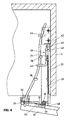
- in the inserted state of the first frame 13 and the second frame 20 is the first frame 13 over the angled part 42, that is Swivel lever 40 is in the rear part with the roller 41 in the raised state.
- the roller 41 runs over a web 43 attached to the base element 6.
- the angled part 42 released, the rear part with the roller 41 of the Swivel lever 40 lowers and comes in front of the web 43.
- the second Frame 20 is thus locked in the advanced position, as shown in the 6 to 8 is shown.
- Snap device 44 is provided, which is fastened to the base element 6, in which can retract a bolt 45 which is fastened to the first frame 13, as can be seen in FIGS. 5 to 8.
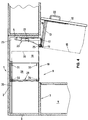
- the arrangement of the first frame 13, the second frame 20 and the wing 19 in the cabinet element 1 with the rear wall 2, the upper cover element 5 and the lower base element 6 can be seen.
- the first frame 13 has two guide rails 35, which are equipped with roller conveyors 36, on which the rollers 37, which are attached to the wing 19, roll.
- This can also be seen as a guideway serving wire piece 24, which with the formed as a pin 26 Interacting guide element.
- the pin 26 is rotatable on the first frame 13 attached and is provided with a recess 46 in which the Wire piece 24 comes to rest.
- the arrangement is also from FIGS. 9 and 10 the locking device 39 and the web 43 can be seen.
- This locking device 39 is shown again in FIG. 11, the pivoting of the pivot lever 14 under the influence of the first Frame 13 is visible, and the roller 41 is shown in the lowered state due to the solid lines, is present on the web 43 and thus pushing back of the second frame 20 is impossible, while with dash-dotted lines Lines the raised position of the pivot lever 40 is shown, in which the roller 41 can run over the web 43, which is an unlocked position corresponds.
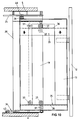
- the carriage 28 consists of a bottom part 47, in which the rollers 31 to 34 are rotatably attached.
- the rollers 31 to 34 are rotatably attached.
- the vertical frame 29 is attached, for example made of metallic Profiles can be formed, which are essentially the shape of a rectangle form.
- the further storage compartments 30 are in this vertical frame 29 attachable, which are formed for example from wire baskets.
- the rollers 31 and 32 run along the guide rail 35 along the bottom element 6 the rear wall 2 is attached.
- the rollers 33 and 34 roll freely on the floor element 6 supported.
- this carriage 28 if the first frame 13 is pulled out of the cabinet element and pivoted away is to be moved against the access 10, what by hand or can optionally be done by other means. This makes accessibility reached on the other storage compartments 30. Before the first frame 13 with the first storage compartments 15 suspended therein again in the cabinet element 1 is pivoted and pushed in, the carriage 28 with the Storage compartments 30 retracted into the corner area of the cabinet element 1 become.
Landscapes
- Cabinets, Racks, Or The Like Of Rigid Construction (AREA)
- Casings For Electric Apparatus (AREA)
- Led Device Packages (AREA)
- Surgical Instruments (AREA)
Priority Applications (8)
| Application Number | Priority Date | Filing Date | Title |
|---|---|---|---|
| EP99810392A EP1050247A1 (fr) | 1999-05-05 | 1999-05-05 | Armoire |
| AT00810212T ATE297671T1 (de) | 1999-05-05 | 2000-03-13 | Schrankelement |
| EP00810212A EP1050246B1 (fr) | 1999-05-05 | 2000-03-13 | Placard |
| DE50010542T DE50010542D1 (de) | 1999-05-05 | 2000-03-13 | Schrankelement |
| ES00810212T ES2241567T3 (es) | 1999-05-05 | 2000-03-13 | Armario. |
| CNB001061232A CN1153536C (zh) | 1999-05-05 | 2000-04-26 | 家具组件 |
| TW089108217A TW503090B (en) | 1999-05-05 | 2000-04-29 | Furnishing element |
| KR10-2000-0023456A KR100384083B1 (ko) | 1999-05-05 | 2000-05-02 | 가구 부품 |
Applications Claiming Priority (1)
| Application Number | Priority Date | Filing Date | Title |
|---|---|---|---|
| EP99810392A EP1050247A1 (fr) | 1999-05-05 | 1999-05-05 | Armoire |
Publications (1)
| Publication Number | Publication Date |
|---|---|
| EP1050247A1 true EP1050247A1 (fr) | 2000-11-08 |
Family
ID=8242811
Family Applications (1)
| Application Number | Title | Priority Date | Filing Date |
|---|---|---|---|
| EP99810392A Withdrawn EP1050247A1 (fr) | 1999-05-05 | 1999-05-05 | Armoire |
Country Status (4)
| Country | Link |
|---|---|
| EP (1) | EP1050247A1 (fr) |
| AT (1) | ATE297671T1 (fr) |
| DE (1) | DE50010542D1 (fr) |
| ES (1) | ES2241567T3 (fr) |
Cited By (2)
| Publication number | Priority date | Publication date | Assignee | Title |
|---|---|---|---|---|
| WO2004091344A1 (fr) * | 2003-04-15 | 2004-10-28 | Vauth-Sagel Holding Gmbh & Co. Kg | Armoire de coin a elements integres mobiles |
| EP1479315A1 (fr) * | 2003-05-23 | 2004-11-24 | Peka-Metall Ag | Tiroir d'armoire |
Citations (5)
| Publication number | Priority date | Publication date | Assignee | Title |
|---|---|---|---|---|
| DE2936601A1 (de) * | 1978-10-09 | 1980-04-17 | Elfa Syst | Zur aufbewahrung von gegenstaenden geeignetes gestell fuer den einbau in einen schrank |
| EP0441919A1 (fr) | 1989-09-04 | 1991-08-21 | Pekametall Ag | Element de meuble pour la mise en place dans un coin rectangulaire d'une piece. |
| DE19514009A1 (de) * | 1995-04-13 | 1996-10-17 | Vauth Sagel Gmbh & Co | Eckschrank zum Aufstellen in einer Raumecke |
| EP0806161A1 (fr) * | 1996-05-06 | 1997-11-12 | Peka-Metall Ag | Système de liens pour le déplacement d'un élément amovible intérieur dans un placard de coin |
| DE29902660U1 (de) * | 1999-02-15 | 1999-04-29 | Yang, Oni, Taipeh/TČai-pei | Speichereinrichtung zur Installation in Ecken von Räumen |
-
1999
- 1999-05-05 EP EP99810392A patent/EP1050247A1/fr not_active Withdrawn
-
2000
- 2000-03-13 AT AT00810212T patent/ATE297671T1/de active
- 2000-03-13 ES ES00810212T patent/ES2241567T3/es not_active Expired - Lifetime
- 2000-03-13 DE DE50010542T patent/DE50010542D1/de not_active Expired - Lifetime
Patent Citations (5)
| Publication number | Priority date | Publication date | Assignee | Title |
|---|---|---|---|---|
| DE2936601A1 (de) * | 1978-10-09 | 1980-04-17 | Elfa Syst | Zur aufbewahrung von gegenstaenden geeignetes gestell fuer den einbau in einen schrank |
| EP0441919A1 (fr) | 1989-09-04 | 1991-08-21 | Pekametall Ag | Element de meuble pour la mise en place dans un coin rectangulaire d'une piece. |
| DE19514009A1 (de) * | 1995-04-13 | 1996-10-17 | Vauth Sagel Gmbh & Co | Eckschrank zum Aufstellen in einer Raumecke |
| EP0806161A1 (fr) * | 1996-05-06 | 1997-11-12 | Peka-Metall Ag | Système de liens pour le déplacement d'un élément amovible intérieur dans un placard de coin |
| DE29902660U1 (de) * | 1999-02-15 | 1999-04-29 | Yang, Oni, Taipeh/TČai-pei | Speichereinrichtung zur Installation in Ecken von Räumen |
Cited By (2)
| Publication number | Priority date | Publication date | Assignee | Title |
|---|---|---|---|---|
| WO2004091344A1 (fr) * | 2003-04-15 | 2004-10-28 | Vauth-Sagel Holding Gmbh & Co. Kg | Armoire de coin a elements integres mobiles |
| EP1479315A1 (fr) * | 2003-05-23 | 2004-11-24 | Peka-Metall Ag | Tiroir d'armoire |
Also Published As
| Publication number | Publication date |
|---|---|
| ES2241567T3 (es) | 2005-11-01 |
| ATE297671T1 (de) | 2005-07-15 |
| DE50010542D1 (de) | 2005-07-21 |
Similar Documents
| Publication | Publication Date | Title |
|---|---|---|
| EP3926136B1 (fr) | Système de guidage pour pièces de meuble | |
| AT519902B1 (de) | Führungssystem zur Führung eines Türflügels | |
| EP3066959B1 (fr) | Tiroir, element de meuble comprenant un tiroir et procede d'ouverture d'un tiroir | |
| DE60110111T2 (de) | Gelenkanordnung für eine schranktür | |
| DE2251560A1 (de) | Schrank mit versenkbarer verschlusswand | |
| WO2008135270A1 (fr) | Ferrure pour armoire d'angle comprenant un plateau monobloc extractible | |
| AT505022B1 (de) | Schrank | |
| EP3500133B1 (fr) | Étagère extractible pour placard | |
| EP2799651B1 (fr) | Ferrure de porte coulissante pour meuble | |
| EP0790022A2 (fr) | Glissière pour tiroirs placée sous le fond du tiroir | |
| EP1050246B1 (fr) | Placard | |
| EP0820244B1 (fr) | Armoire d'angle a placer dans l'angle d'une piece | |
| EP2992157A1 (fr) | Ferrure fonctionnelle pour porte coulissante | |
| DE102009027242A1 (de) | Bewegliche Trennwand | |
| EP1384420B1 (fr) | Mécanisme de fermeture automatique amorti | |
| DE3110110C1 (de) | Duschabtrennung | |
| DE102005017417B4 (de) | Schubladenführung | |
| DE202004007109U1 (de) | Schubladenführung | |
| DE19518499A1 (de) | Schiebetüranordnung | |
| EP1989953B1 (fr) | Armature pour une armoire angulaire dotée d'une étagère en une partie amovible | |
| DE2851094A1 (de) | Schrank mit wenigstens zwei schiebetueren | |
| DE2639304C2 (de) | Schubladenschrank | |
| DE10105847A1 (de) | Mitnahmevorrichtung für ausziehbaren Möbelboden | |
| EP1449999A1 (fr) | Porte pivotante | |
| DE8710798U1 (de) | Türbeschlag |
Legal Events
| Date | Code | Title | Description |
|---|---|---|---|
| PUAI | Public reference made under article 153(3) epc to a published international application that has entered the european phase |
Free format text: ORIGINAL CODE: 0009012 |
|
| AK | Designated contracting states |
Kind code of ref document: A1 Designated state(s): AT BE CH CY DE DK ES FI FR GB GR IE IT LI LU MC NL PT SE |
|
| AX | Request for extension of the european patent |
Free format text: AL;LT;LV;MK;RO;SI |
|
| AKX | Designation fees paid | ||
| REG | Reference to a national code |
Ref country code: DE Ref legal event code: 8566 |
|
| STAA | Information on the status of an ep patent application or granted ep patent |
Free format text: STATUS: THE APPLICATION IS DEEMED TO BE WITHDRAWN |
|
| 18D | Application deemed to be withdrawn |
Effective date: 20010509 |