EP1050341B1 - Röhrenelektrofilter mit beweglichen Elektroden - Google Patents
Röhrenelektrofilter mit beweglichen Elektroden Download PDFInfo
- Publication number
- EP1050341B1 EP1050341B1 EP00109289A EP00109289A EP1050341B1 EP 1050341 B1 EP1050341 B1 EP 1050341B1 EP 00109289 A EP00109289 A EP 00109289A EP 00109289 A EP00109289 A EP 00109289A EP 1050341 B1 EP1050341 B1 EP 1050341B1
- Authority
- EP
- European Patent Office
- Prior art keywords
- electrodes
- tubular
- holder
- shaped
- electrode
- Prior art date
- Legal status (The legal status is an assumption and is not a legal conclusion. Google has not performed a legal analysis and makes no representation as to the accuracy of the status listed.)
- Expired - Lifetime
Links
- 239000000428 dust Substances 0.000 claims abstract description 6
- 238000001556 precipitation Methods 0.000 claims description 9
- 239000012716 precipitator Substances 0.000 claims 3
- SGPGESCZOCHFCL-UHFFFAOYSA-N Tilisolol hydrochloride Chemical compound [Cl-].C1=CC=C2C(=O)N(C)C=C(OCC(O)C[NH2+]C(C)(C)C)C2=C1 SGPGESCZOCHFCL-UHFFFAOYSA-N 0.000 claims 1
- 238000010276 construction Methods 0.000 claims 1
- 238000004140 cleaning Methods 0.000 description 10
- 239000007789 gas Substances 0.000 description 9
- 239000012717 electrostatic precipitator Substances 0.000 description 6
- 239000002245 particle Substances 0.000 description 6
- 230000000694 effects Effects 0.000 description 2
- 150000002500 ions Chemical class 0.000 description 2
- 239000002244 precipitate Substances 0.000 description 2
- 239000007787 solid Substances 0.000 description 2
- 239000002551 biofuel Substances 0.000 description 1
- 230000008021 deposition Effects 0.000 description 1
- 238000006073 displacement reaction Methods 0.000 description 1
- 230000005684 electric field Effects 0.000 description 1
- 239000003546 flue gas Substances 0.000 description 1
- 239000007788 liquid Substances 0.000 description 1
- 238000000034 method Methods 0.000 description 1
- 230000010355 oscillation Effects 0.000 description 1
- 238000000746 purification Methods 0.000 description 1
Images
Classifications
-
- B—PERFORMING OPERATIONS; TRANSPORTING
- B03—SEPARATION OF SOLID MATERIALS USING LIQUIDS OR USING PNEUMATIC TABLES OR JIGS; MAGNETIC OR ELECTROSTATIC SEPARATION OF SOLID MATERIALS FROM SOLID MATERIALS OR FLUIDS; SEPARATION BY HIGH-VOLTAGE ELECTRIC FIELDS
- B03C—MAGNETIC OR ELECTROSTATIC SEPARATION OF SOLID MATERIALS FROM SOLID MATERIALS OR FLUIDS; SEPARATION BY HIGH-VOLTAGE ELECTRIC FIELDS
- B03C3/00—Separating dispersed particles from gases or vapour, e.g. air, by electrostatic effect
- B03C3/02—Plant or installations having external electricity supply
- B03C3/04—Plant or installations having external electricity supply dry type
- B03C3/06—Plant or installations having external electricity supply dry type characterised by presence of stationary tube electrodes
-
- B—PERFORMING OPERATIONS; TRANSPORTING
- B03—SEPARATION OF SOLID MATERIALS USING LIQUIDS OR USING PNEUMATIC TABLES OR JIGS; MAGNETIC OR ELECTROSTATIC SEPARATION OF SOLID MATERIALS FROM SOLID MATERIALS OR FLUIDS; SEPARATION BY HIGH-VOLTAGE ELECTRIC FIELDS
- B03C—MAGNETIC OR ELECTROSTATIC SEPARATION OF SOLID MATERIALS FROM SOLID MATERIALS OR FLUIDS; SEPARATION BY HIGH-VOLTAGE ELECTRIC FIELDS
- B03C3/00—Separating dispersed particles from gases or vapour, e.g. air, by electrostatic effect
- B03C3/34—Constructional details or accessories or operation thereof
- B03C3/40—Electrode constructions
- B03C3/41—Ionising-electrodes
-
- B—PERFORMING OPERATIONS; TRANSPORTING
- B03—SEPARATION OF SOLID MATERIALS USING LIQUIDS OR USING PNEUMATIC TABLES OR JIGS; MAGNETIC OR ELECTROSTATIC SEPARATION OF SOLID MATERIALS FROM SOLID MATERIALS OR FLUIDS; SEPARATION BY HIGH-VOLTAGE ELECTRIC FIELDS
- B03C—MAGNETIC OR ELECTROSTATIC SEPARATION OF SOLID MATERIALS FROM SOLID MATERIALS OR FLUIDS; SEPARATION BY HIGH-VOLTAGE ELECTRIC FIELDS
- B03C3/00—Separating dispersed particles from gases or vapour, e.g. air, by electrostatic effect
- B03C3/34—Constructional details or accessories or operation thereof
- B03C3/74—Cleaning the electrodes
-
- B—PERFORMING OPERATIONS; TRANSPORTING
- B03—SEPARATION OF SOLID MATERIALS USING LIQUIDS OR USING PNEUMATIC TABLES OR JIGS; MAGNETIC OR ELECTROSTATIC SEPARATION OF SOLID MATERIALS FROM SOLID MATERIALS OR FLUIDS; SEPARATION BY HIGH-VOLTAGE ELECTRIC FIELDS
- B03C—MAGNETIC OR ELECTROSTATIC SEPARATION OF SOLID MATERIALS FROM SOLID MATERIALS OR FLUIDS; SEPARATION BY HIGH-VOLTAGE ELECTRIC FIELDS
- B03C3/00—Separating dispersed particles from gases or vapour, e.g. air, by electrostatic effect
- B03C3/34—Constructional details or accessories or operation thereof
- B03C3/86—Electrode-carrying means
-
- B—PERFORMING OPERATIONS; TRANSPORTING
- B03—SEPARATION OF SOLID MATERIALS USING LIQUIDS OR USING PNEUMATIC TABLES OR JIGS; MAGNETIC OR ELECTROSTATIC SEPARATION OF SOLID MATERIALS FROM SOLID MATERIALS OR FLUIDS; SEPARATION BY HIGH-VOLTAGE ELECTRIC FIELDS
- B03C—MAGNETIC OR ELECTROSTATIC SEPARATION OF SOLID MATERIALS FROM SOLID MATERIALS OR FLUIDS; SEPARATION BY HIGH-VOLTAGE ELECTRIC FIELDS
- B03C2201/00—Details of magnetic or electrostatic separation
- B03C2201/10—Ionising electrode with two or more serrated ends or sides
Definitions
- the invention relates to a tubular electrostatic precipitator with at least one tubular collecting electrode and in each case a coaxially arranged wire or rod-shaped discharge electrode.
- Electrostatic precipitators are systems for dedusting of mostly industrial gases, such as top gas, flue gases or the like. Named.
- the mode of operation is based on the corona effect and refers to an electrical discharge form that occurs on sharp edges, tips or wires at atmospheric pressure and high voltages.
- Electrostatic precipitators consist of a discharge electrode, which is usually charged to 35 to 75 kV, which faces a grounded collecting electrode at a suitable distance.
- the precipitation electrode must have a sufficiently large surface area for the precipitation of the filtered-out dust particles and is usually connected to a device for shaking off the precipitate.
- the gas flowing through is ionized, wherein in the electric force field between the two electrodes a directed stream of negative gas ions migrate in the direction of the earthed tube. If a gas with solid or liquid suspended particles is now conveyed by such an electrostatic precipitator, they are bombarded by the ions and likewise charge themselves negatively. As a result of the electric field, the charged particles are driven to the collecting electrode.
- tube electrostatic filters in which a wire-shaped discharge electrode is surrounded by a grounded cylinder, other types, such as plate electrostatic precipitators, are also known.
- EP 397 208 A2 describes a tubular electrostatic filter whose wire-shaped discharge electrodes are fixed on the one hand to a rigid support plate and on the other hand via a magnetic connection to a movable support.
- the holder is hereby centered in the housing, whereby a centering of the Ausströmelektroden is associated within the associated collecting electrodes.
- the holder can be displaced in the plane and, for example, placed in radial oscillations or in circular movements. Accordingly, the wire-shaped Ausströmelektroden be deflected or vibrated.
- the invention now aims to provide a tubular electrostatic filter of the type mentioned, which is also suitable for use in biofuels and can be mechanically cleaned in a particularly simple manner.
- the tube electrostatic filter according to the invention is designed so that the discharge electrode is fixed on both sides to a pivotable or displaceable holding part and from the coaxial to the collecting electrode layer in one of the inner wall of the tubular collecting electrode adjacent position is displaced or pivoted.
- the Ausströmelektrode which may be formed as a wire or rope, can be moved or pivoted in a suitable manner and can be spent in one of the inner wall of the tubular collecting electrode adjacent position, in the now released clear cross-section of the collecting electrode, a corresponding cleaning device, for example a pipe brush or the like, are introduced and efficient rapid cleaning done.
- a corresponding cleaning device for example a pipe brush or the like
- the embodiment of the invention is such that a plurality of cylindrical collecting electrodes is arranged in a common housing, connected to the lower end of a dust funnel is and that the Ausströmelektroden fixed to a common holding part and arranged to be displaced or pivotable with this.
- such a design is such that the axes of the cylindrical electrodes on the circumference of at least one circle are arranged at equal pitch angles to each other and that the common holding part is star-shaped, wherein the length of the arms from the center of the star-shaped part to the clamping point the discharge electrodes corresponds to the radius of the circle and the star-shaped holding part is pivotable about the axis of the circle, such a design in a structurally simple manner allows the common pivoting of the Ausströmelektroden to release the clean cross-section of the collecting electrodes.
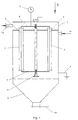
- FIG. 1 shows a schematic side view of a device according to the invention
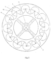
- FIG. 2 shows a plan view in the direction of the arrow II of FIG. 1 of a modified embodiment with the cover of the device according to FIG. 1 removed.
- a plurality of tubular or cylindrical collecting electrodes 2 is arranged in a housing 1.
- wires 3 are stretched, which form the Ausströmelektroden.
- the tubular collecting electrodes are grounded together with the housing 1 via a line 4, whereas the Ausströmelektroden 3 are connected to a high voltage source 5.
- the Ausströmelektroden 3 are at a common carrier or holding part 6 fixed, the lower ends of these discharge electrodes are fixed to a corresponding counter-holder 7.
- the counter-holder 7 is mounted relative to the housing 1 in a bearing 8.
- the lower end of the housing has a funnel-shaped mouth 9, which can be closed by a slider 10.
- the falling dust collects, which can be removed by opening the slider 10.
- corresponding amounts of solids are deposited on the inner wall of the tubular or cylindrical precipitation or precipitation electrodes 2, which must be removed again by mechanical cleaning.
- the upper holding part 6 is formed sternfömig for the Ausströmelektroden 3 and mounted pivotably about an axis 11.
- the pivoting can take place in the sense of the double arrow 12 in such a way that the discharge electrodes 3 are pivoted into the vicinity of the inner wall 13 of the collecting electrodes 2.
- all discharge electrodes 3 can simultaneously be pivoted into such an inoperative position, so that the complete clear cross section of the separating electrodes 2 is released for mechanical cleaning, for example by means of brushes.
Landscapes
- Electrostatic Separation (AREA)
- Separation Using Semi-Permeable Membranes (AREA)
Description
- Die Erfindung bezieht sich auf einen Röhrenelektrofilter mit wenigstens einer rohrförmigen Niederschlagselektrode und jeweils einer koaxial angeordneten draht- oder stabförmigen Ausströmelektrode.
- Als Elektrofilter werden Anlagen zur Entstaubung von zumeist industriellen Gasen, wie Gichtgasen, Rauchgasen oder dgl. benannt. Die Wirkungsweise beruht auf dem Korona-Effekt und bezeichnet eine elektrische Entladungsform, die an scharfen Kanten, an Spitzen oder an Drähten bei Atmosphärendruck und hohen Spannungen auftritt. Elektrofilter bestehen aus einer zumeist auf 35 bis 75 kV aufgeladenen Sprühelektrode, der eine geerdete Niederschlagselektrode in entsprechender Entfernung gegenübersteht. Die Niederschlagselektrode muß eine hinreichend große Oberfläche für den Niederschlag der ausgefilterten Staubteilchen aufweisen und ist zumeist mit einer Vorrichtung zum Abschütteln des Niederschlages verbunden. Durch die angelegte hohe Spannung wird das durchströmende Gas ionisiert, wobei in dem elektrischen Kraftfeld zwischen den beiden Elektroden ein gerichteter Strom von negativen Gasionen in Richtung zum geerdeten Rohr wandern. Wenn durch einen derartigen Elektrofilter nun ein Gas mit festen oder flüssigen Schwebestoffteilchen gefördert wird, so werden diese von den Ionen bombardiert und laden sich gleichfalls negativ auf. Infolge des elektrischen Feldes werden die geladenen Teilchen zur Niederschlagselektrode hingetrieben.
- Neben Röhrenelektrofiltern, bei welchen eine drahtförmige Ausströmelektrode von einem geerdeten Zylinder umgeben ist, sind auch andere Bauformen, wie beispielsweise Plattenelektrofilter, bekannt.
- Bei der Verwendung von derartigen Röhrenelektrofiltern für die Reinigung beispielsweise von Biofeuerungsabgasen stellen sich in der Folge eine Reihe von aufwendigen Reinigungsproblemen, da in derartigen Biofeuerungsabgasen auch teerartige, bituminöse Partikel enthalten sind, welche gemeinsam mit den Staubteilchen eine gut haftende Schicht an der Innenwand der Niederschlagselektrode ergeben. Derartige Filter bedürfen daher einer relativ häufigen Reinigung, wobei mit Rücksicht auf die Anwesenheit von klebrigen, bituminösen Teilchen ein einfaches Abschütteln in der Regel nicht ausreicht, um die Oberflächen der Abscheidungs- bzw. Niederschlagselektrode wieder von dem Niederschlag zu befreien. Derartige Filter müssen daher mechanisch gereinigt werden, wofür Bürsten eingesetzt werden können. Bei Röhrenfilter wird aber die Reinigung der Innenwand der zylinderförmigen Niederschlagelektrode durch die Ausströmelektrode behindert. Es wurden daher bereits alternative Reinigungsmöglichkeiten bekannt. Beispielsweise beschreibt die EP 397 208 A2 einen Röhrenelektrofilter, dessen drahtförmige Ausströmelektroden einerseits an einer starren Tragplatte und andererseits über eine Magnetverbindung an einer beweglichen Halterung festgelegt sind. Die Halterung wird hierbei im Gehäuse zentriert, womit eine Zentrierung der Ausströmelektroden innerhalb der zugehörigen Niederschlagselektroden einhergeht. Durch eine gesteuerte Veränderung der Magnetkräfte in einer bestimmten Abfolge kann die Halterung in der Ebene verlagert und beispielsweise in radiale Schwingungen oder auch in kreisende Bewegungen versetzt werden. Entsprechend werden dann die drahtförmigen Ausströmelektroden ausgelenkt bzw. in Schwingungen versetzt.
- Die Erfindung zielt nun darauf ab, einen Röhrenelektrofilter der eingangs genannten Art zu schaffen, welcher auch für die Verwendung in Biofeuerungsanlagen geeignet ist und in besonders einfacher Weise mechanisch gereinigt werden kann. Zur Lösung dieser Aufgabe ist der erfindungsgemäße Röhrenelektrofilter so ausgebildet, daß die Ausströmelektrode beidseitig an einem verschwenkbaren oder verschiebbaren Halteteil festgelegt ist und aus der zur Niederschlagselektrode koaxialen Lage in eine der Innenwand der rohrförmigen Niederschlagselektrode benachbarte Lage verschieb- oder verschwenkbar ist. Dadurch, daß die Ausströmelektrode, welche als Draht oder Seil ausgebildet sein kann, in geeigneter Weise verschoben oder verschwenkt werden kann und in eine der Innenwand der rohrförmigen Niederschlagselektrode benachbarte Lage verbracht werden kann, kann in den nunmehr freigegebenen lichten Querschnitt der Niederschlagselektrode ein entsprechendes Reinigungsgerät, beispielsweise eine Rohrbürste oder dgl., eingeführt werden und effiziente rasche Reinigung erfolgen. Vor der neuerlichen Inbetriebnahme ist es lediglich erforderlich die Ausströmelektrode wiederum in ihre im wesentlichen koaxiale Lage zum Mantel der zylinderförmigen bzw. rohrförmigen Niederschlagselektrode zurück zu verschieben und zu verschwenken, um auf die Art und Weise die geeignete Ausbildung des Korona-Effekts und die gewünschte gerichtete Strömung beim neuerlichen Reinigungsvorgang zu gewährleisten.
- In besonders vorteilhafter Weise ist die Ausbildung erfindungsgemäß so getroffen, daß eine Mehrzahl von zylinderförmigen Niederschlagselektroden in einem gemeinsamen Gehäuse angeordnet ist, an dessen unterem Ende ein Staubtrichter angeschlossen ist und daß die Ausströmelektroden auf einem gemeinsamen Halteteil festgelegt und mit diesem verschieb- oder verschwenkbar angeordnet sind. Mit einer derartigen eine Mehrzahl von zylinderförmigen Niederschlagselektroden aufweisenden Filtereinrichtung lassen sich auch große Gasmengen mit kleinbauenden Filtern zuverlässig reinigen, wobei die erforderliche Reinigung der Elektroden selbst und insbesondere der Niederschlagselektroden durch die gemeinsame Verschwenkung bzw. Verschiebung der Ausströmelektroden mit geringsten Stillstandszeiten ermöglicht wird.
- In besonders vorteilhafter Weise ist eine derartige Ausbildung so getroffen, daß die Achsen der zylinderförmigen Elektroden am Umfang wenigstens eines Kreises in gleichen Teilungswinkeln zueinander angeordnet sind und daß der gemeinsame Halteteil sternförmig ausgebildet ist, wobei die Länge der Arme vom Mittelpunkt des sternförmigen Teils bis zur Einspannstelle der Ausströmelektroden dem Radius des Kreises entspricht und der sternförmige Halteteil um die Achse des Kreises verschwenkbar ist, wobei eine derartige Ausbildung in konstruktiv einfacher Weise die gemeinsame Verschwenkung der Ausströmelektroden zur Freigabe des zu reinigenden lichten Querschnittes der Niederschlagselektroden ermöglicht.
- Die Erfindung wird nachfolgend anhand eines in der Zeichnung schematisch dargestellten Ausführungsbeispieles näher erläutert. In dieser zeigen Fig. 1 eine schematische Seitenansicht einer erfindungsgemäßen Vorrichtung und Fig. 2 eine Draufsicht in Richtung des Pfeiles II der Fig. 1 auf eine abgewandelte Ausbildung bei abgenommenem Deckel der Vorrichtung nach Fig. 1.
- In Fig. 1 ist in einem Gehäuse 1 eine Mehrzahl von rohrförmigen bzw. zylinderförmigen Niederschlagselektroden 2 angeordnet. Jeweils koaxial zur Achse der rohrförmigen Niederschlagselektroden sind Drähte 3 gespannt, welche die Ausströmelektroden ausbilden. Die rohrförmigen Niederschlagselektroden sind gemeinsam mit dem Gehäuse 1 über eine Leitung 4 geerdet, wohingegen die Ausströmelektroden 3 mit einer Hochspannungsquelle 5 verbunden sind. Die Ausströmelektroden 3 sind an einem gemeinsamen Träger oder Halteteil 6 festgelegt, wobei die unteren Enden dieser Ausströmelektroden an einen entsprechenden Gegenhalter 7 festgelegt sind. Der Gegenhalter 7 ist relativ zum Gehäuse 1 in einem Lager 8 gelagert.
- Das untere Ende des Gehäuses weist eine trichterförmige Mündung 9 auf, welche durch einen Schieber 10 verschließbar ist. In dieser trichterförmigen Mündung 9 sammelt sich der herabfallende Staub, welcher durch Öffnen des Schiebers 10 entfernt werden kann. Im Zuge des Betriebes legen sich an der Innenwand der rohrförmigen bzw. zylinderförmigen Abscheide- bzw. Niederschlagselektroden 2 entsprechende Mengen an Feststoffen fest, welche durch mechanische Reinigung wieder entfernt werden müssen.
- Wie in Fig. 2 dargestellt, ist der obere Halteteil 6 für die Ausströmelektroden 3 sternfömig ausgebildet und um eine Achse 11 verschwenkbar gelagert. Die Verschwenkung kann im Sinne des Doppelpfeiles 12 derart erfolgen, daß die Ausströmelektroden 3 in die Nähe der Innenwand 13 der Niederschlagselektroden 2 verschwenkt werden. Durch Verschwenken des Trägers bzw. Halteteiles 6 können hierbei gleichzeitig alle Ausströmelektroden 3 in eine derartige Außerbetriebstellung verschwenkt werden, sodaß der vollständige lichte Querschnitt der Abscheideelektroden 2 für eine mechanische Reinigung, beispielsweise mittels Bürsten, freigegeben wird.
- Der Vollständigkeit halber ist in Fig. 1 mit 14 der Gaseinlass und mit 15 der Gasauslass für das zu reinigende Gas bezeichnet.
Claims (3)
- Röhrenelektrofilter mit wenigstens einer rohrförmigen Niederschlagselektrode (2) und jeweils einer koaxial angeordneten draht- oder stabförmigen Ausströmelektrode (3), dadurch gekennzeichnet, daß die Ausströmelektrode (3) beidseitig an einem verschwenkbaren oder verschiebbaren Halteteil (6,7) festgelegt ist und aus der zur Niederschlagselektrode (2) koaxialen Lage in eine der Innenwand (13) der rohrförmigen Niederschlagselektrode (12) benachbarte Lage verschieb- oder verschwenkbar ist.
- Röhrenelektrofilter nach Anspruch 1, dadurch gekennzeichnet, daß eine Mehrzahl von zylinderförmigen Niederschlagselektroden (2) in einem gemeinsamen Gehäuse (1) angeordnet ist, an dessen unterem Ende ein Staubtrichter (9) angeschlossen ist und daß die Ausströmelektroden (3) auf einem gemeinsamen Halteteil (6,7) festgelegt und mit diesem verschieb- oder verschwenkbar angeordnet sind.
- Röhrenelektrofilter nach Anspruch 2, dadurch gekennzeichnet, daß die Achsen der zylinderförmigen Elektroden (2) am Umfang wenigstens eines Kreises in gleichen Teilungswinkeln zueinander angeordnet sind und daß der gemeinsame Halteteil (6,7) sternförmig ausgebildet ist, wobei die Länge der Arme vom Mittelpunkt (11) des sternförmigen Teils (6,7) bis zur Einspannstelle der Ausströmelektroden (3) dem Radius des Kreises entspricht und der sternförmige Halteteil (6,7) um die Achse (11) des Kreises verschwenkbar ist.
Priority Applications (1)
| Application Number | Priority Date | Filing Date | Title |
|---|---|---|---|
| AT00109289T ATE316824T1 (de) | 1999-05-03 | 2000-04-29 | Röhrenelektrofilter mit beweglichen elektroden |
Applications Claiming Priority (2)
| Application Number | Priority Date | Filing Date | Title |
|---|---|---|---|
| AT78699 | 1999-05-03 | ||
| AT0078699A AT408846B (de) | 1999-05-03 | 1999-05-03 | Röhrenelektrofilter |
Publications (3)
| Publication Number | Publication Date |
|---|---|
| EP1050341A2 EP1050341A2 (de) | 2000-11-08 |
| EP1050341A3 EP1050341A3 (de) | 2001-01-17 |
| EP1050341B1 true EP1050341B1 (de) | 2006-02-01 |
Family
ID=3499723
Family Applications (1)
| Application Number | Title | Priority Date | Filing Date |
|---|---|---|---|
| EP00109289A Expired - Lifetime EP1050341B1 (de) | 1999-05-03 | 2000-04-29 | Röhrenelektrofilter mit beweglichen Elektroden |
Country Status (3)
| Country | Link |
|---|---|
| EP (1) | EP1050341B1 (de) |
| AT (2) | AT408846B (de) |
| DE (1) | DE50012144D1 (de) |
Cited By (3)
| Publication number | Priority date | Publication date | Assignee | Title |
|---|---|---|---|---|
| EP1958696A2 (de) | 2007-02-16 | 2008-08-20 | Otto Spanner GmbH | Elektrofilter |
| DE102007061199A1 (de) * | 2007-12-16 | 2009-06-18 | Elituus Ltd. & Co. Kg | Kraftwerksanlage und Verfahren zur Behandlung von Prozessluft aus Kraftwerkanlagen |
| KR20230173346A (ko) * | 2022-06-17 | 2023-12-27 | 이앤엠 주식회사 | 배기덕트 없이 미세먼지 및 악취물질을 제거할 수 있는 집진장치 |
Families Citing this family (6)
| Publication number | Priority date | Publication date | Assignee | Title |
|---|---|---|---|---|
| DE102007010973B4 (de) * | 2007-03-05 | 2008-10-16 | Schmatloch Nückel Technologietransfer | Elektrofilter für eine Kleinfeuerungsanlage |
| AT504902B1 (de) * | 2007-09-13 | 2008-09-15 | Buchta Peter | Elektrofilter für eine feuerungsanlage |
| EP2065094B1 (de) | 2007-11-27 | 2016-08-17 | Meister Umwelt Technologie AG | Elektrofilter |
| US8257469B2 (en) * | 2009-03-18 | 2012-09-04 | Meister Environment Technology Ltd. | Electrostatic filter |
| CN107684977A (zh) * | 2017-08-30 | 2018-02-13 | 珠海格力电器股份有限公司 | 一种电净化结构及包含其的空气净化装置 |
| JP7233614B2 (ja) | 2019-09-03 | 2023-03-06 | エスエル-テクニク ゲーエムベーハー | バイオマス暖房システムならびにその構成要素 |
Family Cites Families (5)
| Publication number | Priority date | Publication date | Assignee | Title |
|---|---|---|---|---|
| US2443662A (en) * | 1945-12-29 | 1948-06-22 | Westinghouse Electric Corp | Electrostatic dust precipitator |
| SE452956B (sv) * | 1984-11-05 | 1988-01-04 | Flaekt Ab | For ett flertal emissionselektroder avsedd fasthallningsanordning |
| AT394664B (de) * | 1989-05-02 | 1992-05-25 | Scheuch Alois Gmbh | Elektro-schuettschichtfilter-anlage |
| DE3915639C1 (de) * | 1989-05-12 | 1991-01-24 | Boehler Abfall-Abluft-Abwasser-Umweltschutz Ges.M.B.H., Feldkirch, At | |
| JPH10151363A (ja) * | 1996-11-26 | 1998-06-09 | Shinwa Corp | 多重筒型電気集塵装置 |
-
1999
- 1999-05-03 AT AT0078699A patent/AT408846B/de not_active IP Right Cessation
-
2000
- 2000-04-29 AT AT00109289T patent/ATE316824T1/de not_active IP Right Cessation
- 2000-04-29 DE DE50012144T patent/DE50012144D1/de not_active Expired - Lifetime
- 2000-04-29 EP EP00109289A patent/EP1050341B1/de not_active Expired - Lifetime
Cited By (4)
| Publication number | Priority date | Publication date | Assignee | Title |
|---|---|---|---|---|
| EP1958696A2 (de) | 2007-02-16 | 2008-08-20 | Otto Spanner GmbH | Elektrofilter |
| DE102007061199A1 (de) * | 2007-12-16 | 2009-06-18 | Elituus Ltd. & Co. Kg | Kraftwerksanlage und Verfahren zur Behandlung von Prozessluft aus Kraftwerkanlagen |
| DE102007061199B4 (de) * | 2007-12-16 | 2010-02-11 | Elituus Ltd. & Co. Kg | Kraftwerksanlage und Verfahren zur Behandlung von Prozessluft aus Kraftwerkanlagen |
| KR20230173346A (ko) * | 2022-06-17 | 2023-12-27 | 이앤엠 주식회사 | 배기덕트 없이 미세먼지 및 악취물질을 제거할 수 있는 집진장치 |
Also Published As
| Publication number | Publication date |
|---|---|
| ATE316824T1 (de) | 2006-02-15 |
| ATA78699A (de) | 2001-08-15 |
| AT408846B (de) | 2002-03-25 |
| DE50012144D1 (de) | 2006-04-13 |
| EP1050341A2 (de) | 2000-11-08 |
| EP1050341A3 (de) | 2001-01-17 |
Similar Documents
| Publication | Publication Date | Title |
|---|---|---|
| EP0087778B1 (de) | Zyklon zur Reinigung von Gas mit innerhalb des Zyklons angeordnetem Filter | |
| EP1050341B1 (de) | Röhrenelektrofilter mit beweglichen Elektroden | |
| DE202007004263U1 (de) | Elektrofilter | |
| DE2742625C2 (de) | ||
| AT408843B (de) | Staubfilter | |
| DE3523985A1 (de) | Staubabscheider | |
| DE102015204168A1 (de) | Elektrostatische Partikelabscheidevorrichtung | |
| DE102011052946A1 (de) | Elektroabscheider | |
| EP0482505A1 (de) | Wirbler-Filter-Kombination zum Abscheiden von in Gasen oder Dämpfen dispergierten Teilchen | |
| DE2544698B2 (de) | Abstreichanordnung für Staubteilchen eines Elektroabscheider« | |
| DE4326757A1 (de) | Elektrofilter | |
| EP0875275A1 (de) | Filtermedium zur Trockenabscheidung | |
| DE2307508A1 (de) | Elektrische ausfaellvorrichtung | |
| DE102008018207B3 (de) | Schornsteinsystem mit Elektrostaubfilter | |
| EP2266702A1 (de) | Elektrostatischer Abscheider zur Rauchgasreinigung mit einem elektrischen Sperrfeld | |
| EP1626794B1 (de) | Filterelement | |
| EP0352451A2 (de) | Elektrofilter | |
| DE10126048B4 (de) | Vorrichtung zum Reinigen staubbeladener Rohgase | |
| DE588707C (de) | Vorrichtung zur elektrischen Abscheidung und Rueckgewinnung von staubfoermigen Stoffen aus Gasen | |
| AT393969B (de) | Verfahren zur abreinigung der ionisationselektroden und des rohgasraumes bei einer elektro-schuettschichtfilter-anlage sowie eine anlage, bei welcher das besagte verfahren zur anwendung kommt | |
| DE3744677A1 (de) | Vorrichtung zur aufbereitung, insbesondere filtrierung, der raumluft | |
| DE2340432A1 (de) | Gasreiniger | |
| EP2062649A2 (de) | Elektrostatischer Abscheider mit Partikelabweisemittel, Heizungssystem und Verfahren zum Betrieb | |
| DE102006009765B4 (de) | Röhrenelektrofilter | |
| DE2501463C2 (de) | Elektrostatisches Gerät zum Reinigen von Raumluft durch Ionisieren |
Legal Events
| Date | Code | Title | Description |
|---|---|---|---|
| PUAI | Public reference made under article 153(3) epc to a published international application that has entered the european phase |
Free format text: ORIGINAL CODE: 0009012 |
|
| AK | Designated contracting states |
Kind code of ref document: A2 Designated state(s): AT BE CH CY DE DK ES FI FR GB GR IE IT LI LU MC NL PT SE |
|
| AX | Request for extension of the european patent |
Free format text: AL;LT;LV;MK;RO;SI |
|
| PUAL | Search report despatched |
Free format text: ORIGINAL CODE: 0009013 |
|
| AK | Designated contracting states |
Kind code of ref document: A3 Designated state(s): AT BE CH CY DE DK ES FI FR GB GR IE IT LI LU MC NL PT SE |
|
| AX | Request for extension of the european patent |
Free format text: AL;LT;LV;MK;RO;SI |
|
| RIC1 | Information provided on ipc code assigned before grant |
Free format text: 7B 03C 3/74 A, 7B 03C 3/86 B, 7B 03C 3/06 B, 7B 03C 3/41 B |
|
| 17P | Request for examination filed |
Effective date: 20010208 |
|
| AKX | Designation fees paid |
Free format text: AT BE CH CY DE DK ES FI FR GB GR IE IT LI LU MC NL PT SE |
|
| 17Q | First examination report despatched |
Effective date: 20030521 |
|
| GRAP | Despatch of communication of intention to grant a patent |
Free format text: ORIGINAL CODE: EPIDOSNIGR1 |
|
| GRAS | Grant fee paid |
Free format text: ORIGINAL CODE: EPIDOSNIGR3 |
|
| GRAA | (expected) grant |
Free format text: ORIGINAL CODE: 0009210 |
|
| AK | Designated contracting states |
Kind code of ref document: B1 Designated state(s): AT BE CH CY DE DK ES FI FR GB GR IE IT LI LU MC NL PT SE |
|
| PG25 | Lapsed in a contracting state [announced via postgrant information from national office to epo] |
Ref country code: IT Free format text: LAPSE BECAUSE OF FAILURE TO SUBMIT A TRANSLATION OF THE DESCRIPTION OR TO PAY THE FEE WITHIN THE PRE;WARNING: LAPSES OF ITALIAN PATENTS WITH EFFECTIVE DATE BEFORE 2007 MAY HAVE OCCURRED AT ANY TIME BEFORE 2007. THE CORRECT EFFECTIVE DATE MAY BE DIFFERENT FROM THE ONE RECORDED.SCRIBED TIME-LIMIT Effective date: 20060201 Ref country code: NL Free format text: LAPSE BECAUSE OF FAILURE TO SUBMIT A TRANSLATION OF THE DESCRIPTION OR TO PAY THE FEE WITHIN THE PRESCRIBED TIME-LIMIT Effective date: 20060201 Ref country code: IE Free format text: LAPSE BECAUSE OF FAILURE TO SUBMIT A TRANSLATION OF THE DESCRIPTION OR TO PAY THE FEE WITHIN THE PRESCRIBED TIME-LIMIT Effective date: 20060201 Ref country code: FI Free format text: LAPSE BECAUSE OF FAILURE TO SUBMIT A TRANSLATION OF THE DESCRIPTION OR TO PAY THE FEE WITHIN THE PRESCRIBED TIME-LIMIT Effective date: 20060201 Ref country code: GB Free format text: LAPSE BECAUSE OF FAILURE TO SUBMIT A TRANSLATION OF THE DESCRIPTION OR TO PAY THE FEE WITHIN THE PRESCRIBED TIME-LIMIT Effective date: 20060201 |
|
| REG | Reference to a national code |
Ref country code: GB Ref legal event code: FG4D Free format text: NOT ENGLISH |
|
| REG | Reference to a national code |
Ref country code: CH Ref legal event code: EP |
|
| REG | Reference to a national code |
Ref country code: IE Ref legal event code: FG4D Free format text: LANGUAGE OF EP DOCUMENT: GERMAN |
|
| REF | Corresponds to: |
Ref document number: 50012144 Country of ref document: DE Date of ref document: 20060413 Kind code of ref document: P |
|
| PG25 | Lapsed in a contracting state [announced via postgrant information from national office to epo] |
Ref country code: AT Free format text: LAPSE BECAUSE OF NON-PAYMENT OF DUE FEES Effective date: 20060429 |
|
| PG25 | Lapsed in a contracting state [announced via postgrant information from national office to epo] |
Ref country code: MC Free format text: LAPSE BECAUSE OF NON-PAYMENT OF DUE FEES Effective date: 20060430 |
|
| PG25 | Lapsed in a contracting state [announced via postgrant information from national office to epo] |
Ref country code: SE Free format text: LAPSE BECAUSE OF FAILURE TO SUBMIT A TRANSLATION OF THE DESCRIPTION OR TO PAY THE FEE WITHIN THE PRESCRIBED TIME-LIMIT Effective date: 20060501 Ref country code: DK Free format text: LAPSE BECAUSE OF FAILURE TO SUBMIT A TRANSLATION OF THE DESCRIPTION OR TO PAY THE FEE WITHIN THE PRESCRIBED TIME-LIMIT Effective date: 20060501 |
|
| PG25 | Lapsed in a contracting state [announced via postgrant information from national office to epo] |
Ref country code: ES Free format text: LAPSE BECAUSE OF FAILURE TO SUBMIT A TRANSLATION OF THE DESCRIPTION OR TO PAY THE FEE WITHIN THE PRESCRIBED TIME-LIMIT Effective date: 20060512 |
|
| NLV1 | Nl: lapsed or annulled due to failure to fulfill the requirements of art. 29p and 29m of the patents act | ||
| PG25 | Lapsed in a contracting state [announced via postgrant information from national office to epo] |
Ref country code: PT Free format text: LAPSE BECAUSE OF FAILURE TO SUBMIT A TRANSLATION OF THE DESCRIPTION OR TO PAY THE FEE WITHIN THE PRESCRIBED TIME-LIMIT Effective date: 20060703 |
|
| GBV | Gb: ep patent (uk) treated as always having been void in accordance with gb section 77(7)/1977 [no translation filed] |
Effective date: 20060201 |
|
| REG | Reference to a national code |
Ref country code: IE Ref legal event code: FD4D |
|
| PLBE | No opposition filed within time limit |
Free format text: ORIGINAL CODE: 0009261 |
|
| STAA | Information on the status of an ep patent application or granted ep patent |
Free format text: STATUS: NO OPPOSITION FILED WITHIN TIME LIMIT |
|
| 26N | No opposition filed |
Effective date: 20061103 |
|
| EN | Fr: translation not filed | ||
| PG25 | Lapsed in a contracting state [announced via postgrant information from national office to epo] |
Ref country code: GR Free format text: LAPSE BECAUSE OF FAILURE TO SUBMIT A TRANSLATION OF THE DESCRIPTION OR TO PAY THE FEE WITHIN THE PRESCRIBED TIME-LIMIT Effective date: 20060502 Ref country code: FR Free format text: LAPSE BECAUSE OF FAILURE TO SUBMIT A TRANSLATION OF THE DESCRIPTION OR TO PAY THE FEE WITHIN THE PRESCRIBED TIME-LIMIT Effective date: 20070323 |
|
| PG25 | Lapsed in a contracting state [announced via postgrant information from national office to epo] |
Ref country code: LU Free format text: LAPSE BECAUSE OF NON-PAYMENT OF DUE FEES Effective date: 20060429 |
|
| PG25 | Lapsed in a contracting state [announced via postgrant information from national office to epo] |
Ref country code: FR Free format text: LAPSE BECAUSE OF FAILURE TO SUBMIT A TRANSLATION OF THE DESCRIPTION OR TO PAY THE FEE WITHIN THE PRESCRIBED TIME-LIMIT Effective date: 20060430 |
|
| PG25 | Lapsed in a contracting state [announced via postgrant information from national office to epo] |
Ref country code: CY Free format text: LAPSE BECAUSE OF FAILURE TO SUBMIT A TRANSLATION OF THE DESCRIPTION OR TO PAY THE FEE WITHIN THE PRESCRIBED TIME-LIMIT Effective date: 20060201 Ref country code: FR Free format text: LAPSE BECAUSE OF FAILURE TO SUBMIT A TRANSLATION OF THE DESCRIPTION OR TO PAY THE FEE WITHIN THE PRESCRIBED TIME-LIMIT Effective date: 20060201 |
|
| PGFP | Annual fee paid to national office [announced via postgrant information from national office to epo] |
Ref country code: BE Payment date: 20081203 Year of fee payment: 9 |
|
| BERE | Be: lapsed |
Owner name: FORSTHUBER, PAUL Effective date: 20090430 |
|
| PG25 | Lapsed in a contracting state [announced via postgrant information from national office to epo] |
Ref country code: BE Free format text: LAPSE BECAUSE OF NON-PAYMENT OF DUE FEES Effective date: 20090430 |
|
| REG | Reference to a national code |
Ref country code: CH Ref legal event code: PUE Owner name: APF ADVANCED PARTICLE FILTERS GMBH Free format text: FORSTHUBER, PAUL#NIEDERALM 78#A-5081 ANIF (AT) -TRANSFER TO- APF ADVANCED PARTICLE FILTERS GMBH#HANNAKSTRASSE 3A#5023 SALZBURG-GNIGL (AT) Ref country code: CH Ref legal event code: NV Representative=s name: OK PAT AG PATENTE MARKEN LIZENZEN |
|
| REG | Reference to a national code |
Ref country code: DE Ref legal event code: R081 Ref document number: 50012144 Country of ref document: DE Owner name: APF ADVANCED PARTICLE FILTERS GMBH, AT Free format text: FORMER OWNER: FORSTHUBER, PAUL, ANIF, AT Effective date: 20130107 |
|
| PGFP | Annual fee paid to national office [announced via postgrant information from national office to epo] |
Ref country code: DE Payment date: 20160830 Year of fee payment: 17 |
|
| REG | Reference to a national code |
Ref country code: DE Ref legal event code: R119 Ref document number: 50012144 Country of ref document: DE |
|
| REG | Reference to a national code |
Ref country code: CH Ref legal event code: PL |
|
| PG25 | Lapsed in a contracting state [announced via postgrant information from national office to epo] |
Ref country code: DE Free format text: LAPSE BECAUSE OF NON-PAYMENT OF DUE FEES Effective date: 20171103 |
|
| REG | Reference to a national code |
Ref country code: CH Ref legal event code: AECN Free format text: DAS PATENT IST AUFGRUND DES WEITERBEHANDLUNGSANTRAGS VOM 23.01.2018 REAKTIVIERT WORDEN. |
|
| PG25 | Lapsed in a contracting state [announced via postgrant information from national office to epo] |
Ref country code: LI Free format text: LAPSE BECAUSE OF NON-PAYMENT OF DUE FEES Effective date: 20170430 Ref country code: CH Free format text: LAPSE BECAUSE OF NON-PAYMENT OF DUE FEES Effective date: 20170430 |
|
| PG25 | Lapsed in a contracting state [announced via postgrant information from national office to epo] |
Ref country code: CH Free format text: LAPSE BECAUSE OF NON-PAYMENT OF DUE FEES Effective date: 20170430 Ref country code: LI Free format text: LAPSE BECAUSE OF NON-PAYMENT OF DUE FEES Effective date: 20170430 |
|
| PGRI | Patent reinstated in contracting state [announced from national office to epo] |
Ref country code: LI Effective date: 20180124 Ref country code: CH Effective date: 20180124 |
|
| REG | Reference to a national code |
Ref country code: DE Ref legal event code: R124 Ref document number: 50012144 Country of ref document: DE |
|
| PGFP | Annual fee paid to national office [announced via postgrant information from national office to epo] |
Ref country code: CH Payment date: 20190604 Year of fee payment: 20 |
|
| REG | Reference to a national code |
Ref country code: CH Ref legal event code: PL |