EP1050377A2 - Rotierendes Maschinen-Schleifwerkzeug - Google Patents
Rotierendes Maschinen-Schleifwerkzeug Download PDFInfo
- Publication number
- EP1050377A2 EP1050377A2 EP00105792A EP00105792A EP1050377A2 EP 1050377 A2 EP1050377 A2 EP 1050377A2 EP 00105792 A EP00105792 A EP 00105792A EP 00105792 A EP00105792 A EP 00105792A EP 1050377 A2 EP1050377 A2 EP 1050377A2
- Authority
- EP
- European Patent Office
- Prior art keywords
- grinding tool
- carrier body
- abrasive
- tool according
- disc
- Prior art date
- Legal status (The legal status is an assumption and is not a legal conclusion. Google has not performed a legal analysis and makes no representation as to the accuracy of the status listed.)
- Granted
Links
Images




Classifications
-
- B—PERFORMING OPERATIONS; TRANSPORTING
- B24—GRINDING; POLISHING
- B24D—TOOLS FOR GRINDING, BUFFING OR SHARPENING
- B24D13/00—Wheels having flexibly-acting working parts, e.g. buffing wheels; Mountings therefor
- B24D13/14—Wheels having flexibly-acting working parts, e.g. buffing wheels; Mountings therefor acting by the front face
-
- B—PERFORMING OPERATIONS; TRANSPORTING
- B24—GRINDING; POLISHING
- B24B—MACHINES, DEVICES, OR PROCESSES FOR GRINDING OR POLISHING; DRESSING OR CONDITIONING OF ABRADING SURFACES; FEEDING OF GRINDING, POLISHING, OR LAPPING AGENTS
- B24B9/00—Machines or devices designed for grinding edges or bevels on work or for removing burrs; Accessories therefor
- B24B9/02—Machines or devices designed for grinding edges or bevels on work or for removing burrs; Accessories therefor characterised by a special design with respect to properties of materials specific to articles to be ground
- B24B9/18—Machines or devices designed for grinding edges or bevels on work or for removing burrs; Accessories therefor characterised by a special design with respect to properties of materials specific to articles to be ground of wood
-
- B—PERFORMING OPERATIONS; TRANSPORTING
- B24—GRINDING; POLISHING
- B24D—TOOLS FOR GRINDING, BUFFING OR SHARPENING
- B24D13/00—Wheels having flexibly-acting working parts, e.g. buffing wheels; Mountings therefor
- B24D13/02—Wheels having flexibly-acting working parts, e.g. buffing wheels; Mountings therefor acting by their periphery
-
- B—PERFORMING OPERATIONS; TRANSPORTING
- B24—GRINDING; POLISHING
- B24D—TOOLS FOR GRINDING, BUFFING OR SHARPENING
- B24D13/00—Wheels having flexibly-acting working parts, e.g. buffing wheels; Mountings therefor
- B24D13/20—Mountings for the wheels
-
- B—PERFORMING OPERATIONS; TRANSPORTING
- B24—GRINDING; POLISHING
- B24D—TOOLS FOR GRINDING, BUFFING OR SHARPENING
- B24D9/00—Wheels or drums supporting in exchangeable arrangement a layer of flexible abrasive material, e.g. sandpaper
- B24D9/04—Rigid drums for carrying flexible material
Definitions
- the invention relates to a rotationally drivable Machine grinding tool consisting of one Carrier body, which by means of connecting elements to a Machine drive can be used and the at least one can be brought into contact with a workpiece to be ground Has a work surface that is equipped with abrasives.
- Grinding disks are known. Their working surfaces are usually equipped with abrasive cloth which serves as an abrasive. All surfaces of a disc can be used as the working surface which, when the disc rotates, are moved around the center of rotation of the disc with sufficient peripheral speed for grinding of the grinding wheels at the highest, so that surface areas located there are mostly equipped with grinding lines and the so-called Work surfaces "there.
- the work surfaces can be used to grind profiles of the grinding tools according to the one to be ground Profile be contoured.
- the contoured work surface is stuck with abrasive cloth that is so thin that it can be nestled into the contours. Used up Grinding lines must be removed from the grinding tool regularly loosened and re-glued on abrasive cloth be replaced.
- Grinding tools are included for each profile appropriate contouring is required, with several prepared and contoured grinding tools are to be provided simultaneously to the grinding process same workpieces not with long set-up and Interrupt downtimes and therefore inexpensive to have to burden.
- the invention is based on the object to provide a rotationally drivable grinding tool, that can be used universally and economically for any grinding work on workpieces, in particular Workpieces with a profiled surface, such as turned workpieces, profile strips or the like.
- the carrier body is designed as a disc, the is so thin, e.g. 1 mm that they are transverse to Disc level can spring elastically and in Disc center an approach to the fasteners and that the abrasive is a flat structure with one side with abrasive cloth, sandpaper or the same abrasive layer coated elastic Upholstery layer is, which, in the manner of a surround the outer edge of the disc with which Padding layer is attached to the support body.
- the formation of the carrier body as a disc has the Advantage that the support body at transverse to the plane of the disc pressure forces during grinding can yield resiliently. This enables an advantageous one soft grinding. In addition, this property of soft grinding also further promoted in that Carrier body or the disc grinding lines attached which is a cushion layer on its underside having.
- this cushioning layer both the two, about disc surfaces radially to the center of rotation, at least in the area of the periphery of the disc, as well the outer edge or the outer edge of the plate-shaped, as a disk or plate present carrier body in the Surrounding type of surround can also in essential radially acting pressure forces from the Cushion layer are cushioned, so that even with the narrow radius of the wrapped around the edge or the edge Sanding relatively aggressive, but without Chatter marks and without excessive friction heat builds up, especially at the bottom narrower and deeper Profiling of the workpieces, soft grinding.
- the grinding tool is advantageously relatively flat, so it is suitable to narrow grooves and punctures, as they are especially with wood turning parts or Turned parts made of metal and copper materials occur grind.
- the grinding tool according to the invention can for Grinding work is used, for which so far Contoured grinding wheels were required so that now a universal grinding tool is present.
- the abrasive is a flat structure that means a section or part of a band, a plate, a sanding sheet or similar raw or Starting element that is a layer Abrasive cloth or sandpaper according to desired Has grit on one side, the non-abrasive Back, equipped with an elastic padding layer is.
- the cushion layer is advantageously a foam appropriate porosity and elasticity. Not to them abrasive surface of the back, for example one Sanding, the upholstery is laminated or is the cushion layer with the surface of the back firmly connected, for example in that the foam foamed directly on the back of the sanding line is.
- the cushion layer has a thickness of approximately 1 to 5 mm, preferably 2.5-3 mm. Thinner upholstery layers can be easily pushed through with high sanding pressure, i.e. they can pierce locally, which means that the advantages of soft sanding are lost. On the other hand, thicker cushion layers have the disadvantage that they stretch or stretch excessively due to centrifugal forces, which can lead to undesired changes in shape and, under certain circumstances, detachment from the carrier body. A thickness of the cushion layer of approximately 2.5 mm and an open-cell plastic foam with a compression hardness of 10 - 60 and a density of 17 - 40 kg per m 3 have proven effective.
- a grinding tool in which the carrier body is also designed as a disc that is so thin is that it can spring elastically across the plane of the disc and those in the disc center an approach for that Has fasteners on rotating parts of a machine drive are present and that with the An abrasive that can be combined with a carrier body is a Ring body made of elastic material in the area its periphery with abrasive cloth, sandpaper or the same abrasive layer is provided and the Carrier body is attached.
- Carrier body and ring body together form one unit usable as a grinding tool attached to a Machine drive is attachable.
- the disk serving as the carrier body is in both Solutions according to the invention advantageously as a disc ring trained because the inner hole of a disc ring as Approach for fasteners can serve.
- the Hole edge of the inner hole for example, corresponding Have material reinforcements or thickenings that to recordings for clamping elements Fasteners can be formed, with which the Grinding tool on or on one through the inner hole extending, or protruding into the inner hole Shaft, a hollow cylinder, a bushing or a pin of a machine drive can be tensioned.
- the approach of the carrier body is a short e.g. 7 mm long sleeve formed, the disc about a radially protruding from the sleeve about 10 mm wide Collar flange corresponds.
- Form sleeve with collar flange thus the carrier body, which is identified by means of the sleeve Approach a wave easily, quickly and easily Hollow cylinder, a socket, a pin or the like rotating part of a machine drive is stuck and because of the sleeve also centered sufficiently precisely is.
- the configuration of the carrier body is like this hit that the corresponding to the disc Collar flange, based on the length of the sleeve, sits off-center on the sleeve.
- the inner surface of the sleeve can be radially inward protruding drivers that are in corresponding grooves e.g. the as a hollow cylinder, socket or the like present connecting elements or directly in the shaft or a journal of the machine drive intervene and ensure that the Ensure grinding tool.
- the sleeve and collar flange are particularly advantageous as a one-piece plastic injection-molded part.
- the sleeve and collar flange have roughly the same wall thickness and can be manufactured inexpensively from plastic in large quantities using the injection molding process.
- Other materials for the carrier body for example sheet metal, are possible.
- the collar flange has been edged with the padded abrasive, there is a cheap grinding tool that can be used universally for many grinding jobs and can be easily replaced after the abrasive layer has worn out.
- Worn grinding tools of the type according to the invention do not require reprocessing, as is the case with profiled grinding tools, but can also be completely disposed of.
- the grinding tools according to the invention are thus so-called Disposable Parts ".
- the plastic used to form the carrier body is, with particular advantage, a glass fiber reinforced polyamide.
- the glass fiber reinforcement produces the necessary strength despite the thin-walled design of the carrier body, but allows the desired resilient properties of the collar flange itself, i.e. also the yielding of the entire disc with appropriate pressure on a workpiece to be ground.
- a polyamide has the additional advantage that this material can be dissolved with formic acid, so that dissolved areas can act like an applied adhesive. As a result, after wetting the surfaces of the collar flange with formic acid, the abrasive with its cushioning layer or the alternatively provided ring body can be connected to the carrier body without any problem and without additional use of special adhesives.
- the cushion layer is an open-cell foam with which the detached material of the carrier body can bond particularly intensively and firmly, since the detached material can penetrate into the pores of the foam and for anchoring on the other side ensures as soon as the solvent evaporates and the Adhesive "has dried.
- the one intended as an alternative abrasive Ring body consists of a plastic foam, preferably polyurethane foam of predetermined hardness.
- the abrasive can be attached simply be designed so that the abrasive is in shape a predetermined, for dimensioning the Carrier body or the ring body in each case matching Blank is present. Cuts can be prepared and provide around the carrier body or ring body to equip with it. From plates, tapes, strips or the same raw material of the abrasive can be manufacture the corresponding blanks without further ado. Conveniently, everyone is directly on the carrier body attachable cut a flat, essentially round Stamped part with wedge-shaped edge cuts or Notches.
- edge incisions or notches make it possible to cut the abrasive according to Art an edging wrinkle-free around the outer edge of the Washer or the collar flange or to the curved Lay the work surface of the ring body.
- a hole is arranged in the center of the blank, the Diameter about the same, but not less than that Outside diameter of the approach of the sleeve Carrier body is. The hole in the center of the blank thus hinders attachment of the grinding tool a shaft or a clamping pin of a machine drive Not.
- the outer diameter of the ring body is so dimensioned that its outer peripheral surface the outer edge of the collar flange of the support body around pre-determined dimension and that the carrier body area of the outer peripheral surface of the Ring body has the abrasive layer. Because the ring body consists of elastic plastic foam, it forms a for the grinding behavior advantageous cushion, the the outer dimensions of the carrier body are outstanding Regions of the ring body even more advantageous Way can give way to an increased grinding pressure, because such protruding or outstanding areas of the somewhat stiffer collar flange of the carrier body to be supported excessively.
- a region facing away from the carrier body can be a fillet or similar profile be, which in turn has the abrasive layer. Fillets with different radii and varying dimensions of the bevels allow inexpensive provision various, universally usable grinding tools.
- the grinding tools can be operated with machine drives easy and quick connection, as a machine drive one on a drive journal of a machine includes stretchable hollow cylinder, the outer diameter is equal to the inside diameter of the carrier body and on the at least one of a carrier body with a ring body existing grinding tool attachable and by means of a Fixing member is attachable.
- the hollow cylinder also called a bush has a length that allows various grinding tools on the hollow cylinder to line up.
- the mutual alignment and assignment the grinding tools can be taken so that Abrasive tool combinations are formed that the each workpiece to be ground, in particular profiled workpiece.
- With new grinding tools equipped hollow cylinders can be provided, so that a changeover in an advantageously short assembly time is possible. Business interruptions can be on Press minimum.
- Every clamp ring has at least one clamping screw so that it is in Any slide-on position can be fixed on the hollow cylinder is.
- Spacers can be a predetermined distance between two attached to a hollow cylinder Adjust grinding tools.
- Each hollow cylinder has in its peripheral surface at least one longitudinal groove, in each of which one of the Carrier of a carrier body one on the hollow cylinder inserted grinding tool engages positively.
- the Hollow cylinder forms a rotating part of the machine drive and takes the attached body with the abrasive on it.
- spacers in a longitudinal groove rod parts which can be inserted in a form-fitting manner.
- Each Rod part is one of a plastic profile rod cut piece with the desired length.
- In the longitudinal groove of the hollow cylinder can also Engage the clamping screw of a clamping ring.
- Spacers must be relative be dimensioned or dimensioned by what machining is done. For the user of the This means that it has a variety of grinding tools Spacers made with the highest accuracy or - wrestle must be ready, which may be right time consuming and tedious way to get together combine to get the desired distance between two grinding tools on a hollow cylinder adjust.
- the rod parts make it possible in advantageously, a piece of predetermined length cut that off in the longitudinal groove of the hollow cylinder is used. That turns out from the rod part cut piece as too long, it can be easiest Be cut shorter. This measure is everyone relevant craftsmen familiar.
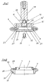
- Fig. 1 shows a grinding tool in the Side view cut.
- the grinding tool is there from a carrier body 1, in the peripheral region thereof Abrasive 2 is arranged.
- the carrier body is made from a disc 3 that is so thin e.g. 1 mm that it can spring elastically across the disc plane. in the Disc center is as an approach for Fasteners an approximately 7 mm short sleeve 4, wherein disk 3 approximately radially from sleeve 4 protruding collar flange corresponds.
- the abrasive 2 is a flat structure, which in the manner of a border around the outer edge 5 the disc 3 is placed.
- the abrasive includes a Abrasive cloth 6, one on the back has elastic cushion layer 7.
- the upholstery layer can Be foam or plastic foam and has one Thickness of about 2.5 mm, which gives good molding properties of the abrasive can be achieved. With The outer radius of the abrasive can be advantageous keep the area of the outer edge 5 small.
- Fig. 2 shows the carrier body 1 in one Side view.
- the same components are the same Reference numerals as designated in Fig. 1.
- Fig. 2 leaves especially in connection with Fig. 1 recognize that the the corresponding flange 3 collar flange based on the Length of the sleeve 4 sits off-center on the sleeve.
- Fig. 1 illustrates the thickness of the abrasive larger than the smallest distance of the disc 3 corresponding collar flange from the end 8 of the sleeve (Fig. 2), so that the advantageous visible in Fig. 1
- the excess of the abrasive results in a full Use of the lower front work surface of the Grinding tool (Fig. 1) allows.
- FIG. 3 shows a top view of the carrier body 1 according to Fig. 2.
- the same components are the same Designated reference numbers.
- FIGS. 2 and 3 illustrate in particular the Formation of the carrier body 1 similar to a Disc ring, the inner surface of the sleeve facing radially internally projecting driver 9, which is the non-rotatable Attaching the carrier body to connecting elements or a shaft or spindle of a machine drive guarantee.
- Each carrier part is advantageously an injection molded part made of glass fiber reinforced polyamide, for example under the trade name Ultramid ".
- This is an impact-resistant and highly resilient plastic that enables the bending strength of the approximately 1 mm thin disc 3, which is in the form of a collar flange of the sleeve 4.
- This plastic also develops when dissolved with a suitable solvent, for example formic acid, Adhesive properties that can be used to advantage to connect the carrier body with abrasives.
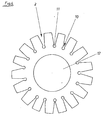
- Fig. 4 shows in a plan view that the Abrasive in the form of a predetermined, for Dimensioning of the support body 3 each appropriate Blank is present.
- Abrasive 2 is a flat, in essential round stamped part with wedge-shaped Edge incisions 10, which are also called notches can be designated.
- the edge incisions 10 in Connection with those at the bottom of the incisions Holes 11 allow a wrinkle-free laying around Abrasive around the outer edge 5 of the form of a Disc 3 present carrier body 1.
- the ring-shaped area between the holes 11 and the inner hole 12 forms a main working side without any cuts. It also enables Inner hole 12 a concealed screw connection or Bracing with the drive machines.
- Fig. 5 shows schematically the preparation of the Grinding tool with connecting means to the shaft 13 of a machine drive.
- the connecting means include a clamping ring 14 seated on the shaft 13, which in Area of its outer circumference has grooves 15, in which the driver 9 of the carrier body 1 of the grinding tool can intervene to rotate the grinding tool to connect the shaft 13.
- the two clamping rings 14 and 16 are here in the manner of one Exploded view drawn. You can screwed or clamped together, which they Then clamp the grinding tool between them.
- Fig. 6 shows a second embodiment of the Connection of the grinding tool with a Machine drive.
- the clamping pin 18 has on the front side of its tenon 19, which can be inserted into the bore 17 is a threaded blind hole 20.
- the outside diameter of the Span lid 21 is approximately the same, but not greater than that Inner diameter of the sleeve of the carrier body 1. This can the stretch lid 21 on the shoulders 23 to the Bottom of the shortened compared to the sleeve length Driver 9 rest.
- the clamping cover 21 is thus in the sleeve sunk when he sunk with the Countersunk screw 24 attached to the pin base 19 of the pin 18 and as soon as all components are caught or Intermediate clamping of the grinding tool put together and have contracted.
- the clamping pin 18 can be placed in a chuck, for example an electric hand drill clamp.
- Fig. 7 shows another particularly advantageous Design option for connecting the grinding tool with a machine drive.
- the exemplary embodiment is a lower one in the clamping ring 14 ′′ Extension 25 of the inner bore 17 is provided in the one Usual spring ring 26 can be inserted.
- the clamping cover 21 also has an exemplary embodiment in FIG grooves 27 and 27 'cut into its circumference on the with the corresponding rotating position of the tension disc stand congruent to the drivers 9 of the carrier body 1, so that it can be pulled down without the Remove the tension cover 21. Likewise, at corresponding rotary position also a new one from below Grinding tool can be pushed on.
- FIG. 8 shows a side view of an alternative Embodiment of a grinding tool in section.
- the Carrier body is again designated 1 and consists of a sleeve 4 with disc 3, which is approximately radial from the collar flange protruding from the sleeve.
- Abrasive is here with the backing connected ring body 28 is provided.
- the ring body 28 consists of a polyurethane foam of predetermined hardness.
- the outer diameter of the ring body 1 is dimensioned that its outer peripheral surface 29 the outer edge 30 of the as a collar flange disc 3 around a pre-determined dimension.
- a to the carrier body 1 turned area 31 of the outer peripheral surface of the Ring body 28 has the abrasive layer 32, which here as dotted line is indicated. That of the carrier body turned area 31 of the outer peripheral surface of the Ring body 28 has a groove, so that appropriately profiled workpieces are ground can.
- FIG. 9 shows an embodiment of a grinding tool acc. Fig. 8, wherein the carrier body 1 with two Ring bodies 28 and 28 'is provided. This execution makes it possible to grind corresponding profiles or the grinding tool is easy to turn as soon as the Abrasive position of one of the ring bodies 28 or 28 'worn out is.
- FIG. 10 shows a ring body, the with Area 31 provided with abrasive layer 32 as a fillet is trained.
- Fig. 11 shows an annular body with a chamfer, the is provided with the abrasive layer 32.
- 12 is the Ring body 28 is not profiled and the periphery is one drawn over the upper edge of the ring body Abrasive layer 32 provided so that a shape is ready to grind a Palatinate.
- Fig. 13 is a longitudinal section of one on here Drive pin of a machine, not shown clamping hollow cylinder 34, part of a machine drive is.
- the outer diameter of the hollow cylinder 34 is the same as the inner diameter Carrier body 1.
- Both carrier bodies are again with fillets having annular bodies 28.
- a Copy ring 36 are set, so that here schematically indicated wooden profile 37 can be sanded.
- the upper carrier body 1 or that of the carrier body 1 and ring body 28 existing grinding tool can on the Hollow cylinder 34 attached with a locking member 38 be, the fixing body here as one on the Hollow cylinder 34 slide-on clamping ring 39 formed is by means of a clamping screw with hexagon socket 41 on the hollow cylinder in any longitudinal sliding position is fixable.
- the clamping ring is on this Embodiment in the direction of arrow 42 still postpone it until it's off the package Abrasive tools rests on the top Carrier body 1 of the first grinding tool strikes.
- FIG. 14 shows a schematic view of a Section of the outer surface of the hollow cylinder 34 with the Longitudinal groove 43.
- the arrow 45 shows like a piece a rod part 44 fits positively in the longitudinal groove.
- a machine drive is schematic Shown view, on the hollow cylinder 34 two Grinding tools are set in an arrangement like it corresponds to Fig. 13, with the grinding tools the ring body 28 visible here are illustrated.
- the Wood profile to be sanded is again designated 37 and the clamping ring with 39.
- Rod part 44 set as a spacer.
- the hollow cylinder so long that an additional cylindrical Grinding tool 46 can be plugged.
- the curves on the Outside edges of the wooden profile 37 can be sanded with the cylindrical surface 46 the straight surface 47 the outer edge of the wooden profile 37 are sanded.
- a new grinding process is carried out at which either the wooden profile 37 by at the Grinding machine existing facilities in a deeper Placed level and on the rotating machine drive is led past.
- the ring body 28 are excluded Function set and only the cylindrical Grinding tool 46 grinds.
- the management level of the wooden profile 37 in the Keep grinder and only the whole Machine drive, i.e. the spindle with the Grinding tools, offset in height to each either the ring body 28 or the abrasive layer on the circumference of the cylindrical grinding tool 46 for use bring.
Landscapes
- Engineering & Computer Science (AREA)
- Mechanical Engineering (AREA)
- Life Sciences & Earth Sciences (AREA)
- Wood Science & Technology (AREA)
- Polishing Bodies And Polishing Tools (AREA)
- Grinding And Polishing Of Tertiary Curved Surfaces And Surfaces With Complex Shapes (AREA)
Abstract
Description

- Fig. 1:
- eine Seitenansicht des Schleifwerkzeuges im Schnitt,
- Fig. 2:
- eine Seitenansicht des Trägerkörpers des Schleifwerkzeuges gemäß Fig. 1 im Schnitt,
- Fig. 3:
- eine Draufsicht des Trägerkörpers gemäß Fig. 2,
- Fig. 4:
- eine Draufsicht eines Zuschnittes aus Schleifmittel zur Ausrüstung des Trägerkörpers gemäß Fig. 2 und 3 zu einem Schleifwerkzeug gemäß Fig. 1,
- Fig. 5:
- eine Seitenansicht des Schleifwerkzeuges mit Verbindungselementen zum Aufspannen auf eine Welle einer Antriebsmaschine,
- Fig. 6:
- eine Seitenansicht eines Schleifwerkzeuges im Schnitt mit Verbindungs elementen zum Ansetzen des Schleifwerkzeuges an einen Spannzapfen einer Antriebsmaschine,
- Fig. 7:
- eine Seitenansicht eines Schleifwerkzeuges im Schnitt entsprechend Fig. 6, mit einer abgewandelten Ausführung der Verbindungselemente zum Ansetzen an den Spannzapfen einer Antriebsmaschine,
- Fig. 8:
- eine Seitenansicht einer alternativen Ausführungsform des Schleifwerkzeuges im Schnitt,
- Fig. 9:
- eine weitere Ausführungsform des Schleifwerkzeuges gem. Fig. 8,
- Fig. 10, 11, 12:
- halbe Seitenansichten der Schleifwerkzeuge mit unterschiedlichen Profilgebungen der mit Abrasivmaterial ausgerüsteten Arbeitsflächen,
- Fig. 13:
- eine Seitenansicht eines Ausführungs beispieles für eines Zusammenbaues aus Maschinen-Antrieb und Schleifwerkzeu gen,
- Fig. 14:
- eine schematische Detailansicht einer Längsnut im Hohlzylinder des Maschinen-Antriebs und eines darin einfügbaren Distanzelements und
- Fig. 15:
- ein Ausführungsbeispiel für die Zusammenstellung bzw. Kombination von Schleifwerkzeugen und deren Anordnung bei einem Maschinen-Antrieb in schematischer Ansicht.
Claims (19)
- Rotierend antreibbares Maschinen-Schleifwerkzeug, bestehend aus einem Trägerkörper, der mittels Verbindungselementen an einen Maschinen-Antrieb ansetzbar ist und der wenigstens eine mit einem zu schleifenden Werkstück in Anlage bringbare Arbeitsfläche hat, die mit Schleifmittel ausgerüstet ist,
dadurch gekennzeichnet,
daß der Trägerkörper (1) als Scheibe (3) ausgebildet ist, die derart dünn ist, daß sie quer zur Scheibenebene elastisch federn kann und die im Scheibenzentrum einen Ansatz für die Verbindungselemente aufweist und daß das Schleifmittel (2) ein flächiges Gebilde mit einer einseitig mit Schleifleinen (6), Schleifpapier oder dergleichen Abrasivlage beschichteten, elastischen Polsterlage (7) ist, welches, nach Art einer Einfassung um die Außenrandkante (5) der Scheibe (3) gelegt, mit der Polsterlage (7) am Trägerkörper (1) befestigt ist. - Rotierend antreibbares Maschinen-Schleifwerkzeug, bestehend aus einem Trägerkörper, der mittels Verbindungselementen an einen Maschinen-Antrieb ansetzbar ist und der wenigstens eine mit einem zu schleifenden Werkstück in Anlage bringbare Arbeitsfläche hat, die mit Schleifmittel ausgerüstet ist, dadurch gekennzeichnet, daß der Trägerkörper (1) als Scheibe (3) ausgebildet ist, die derart dünn ist, daß sie quer zur Scheibenebene elastisch federn kann und die im Scheibenzentrum einen Ansatz für die Verbindungselemente aufweist und daß das Schleifmittel (2) ein Ringkörper (28) aus elastischem Werkstoff ist, der im Bereich (31) seiner Peripherie mit Schleifleinen, Schleifpapier oder dergleichen Abrasivlage (32) versehen ist und der am Trägerkörper (1) befestigt ist.
- Schleifwerkzeug nach einem der Ansprüche 1 oder 2, dadurch gekennzeichnet, daß die Scheibe (3) als Scheibenring ausgebildet ist.
- Schleifwerkzeug nach einem der vorhergehenden Ansprüche, dadurch gekennzeichnet, daß der Ansatz des Trägerkörpers (1) als kurze Hülse (4) ausgebildet ist, wobei die Scheibe (3) einem etwa radial von der Hülse (4) abstehenden Kragenflansch entspricht.
- Schleifwerkzeug nach Anspruch 4, dadurch gekennzeichnet, daß der der Scheibe (3) entsprechende Kragenflansch, bezogen auf die Länge der Hülse (4), von z.B. 7 mm außermittig an der Hülse (4) sitzt.
- Schleifwerkzeug nach einem der vorhergehenden Ansprüche, dadurch gekennzeichnet, daß die Innenfläche der Hülse (4) radial nach Innen abstehende Mitnehmer (9) aufweist.
- Schleifwerkzeug nach einem der vorhergehenden Ansprüche, dadurch gekennzeichnet, daß Hülse (4) und Kragenflansch ein einstückiges Kunststoff-Spritzgußteil sind.
- Schleifwerkzeug nach Anspruch 7, dadurch gekennzeichnet, daß der Kunststoff ein glasfaserverstärktes Polyamid ist.
- Schleifwerkzeug nach Anspruch 1 und einem der Ansprüche 3 bis 8, dadurch gekennzeichnet, daß das Schleifmittel (2) in Form eines vorbestimmten, zur Dimensionierung des Trägerkörpers (1) jeweils passenden Zuschnittes vorliegt.
- Schleifwerkzeug nach Anspruch 9, dadurch gekennzeichnet, daß jeder Zuschnitt ein planes, im wesentlichen rundes Stanzteil mit keilförmigen Randeinschnitten (10) bzw. Ausklinkungen ist.
- Schleifwerkzeug nach einem der Ansprüche 9 und 10, dadurch gekennzeichnet, daß im Zentrum des Zuschnittes ein Loch (12) angeordnet ist, dessen Durchmesser etwa gleich, jedoch nicht kleiner als der Außendurchmesser des als Hülse (4) vorliegenden Ansatzes des Trägerkörpers (1) ist.
- Schleifwerkzeug nach Anspruch 2 und einem der Ansprüche 3 bis 8, dadurch gekennzeichnet, daß der Außendurchmesser des Ringkörpers (28) so bemessen ist, daß seine äußere Umfangsfläche (29) den Außenrand (30) der als Kragenflansch vorliegenden Scheibe (3) um ein vorbestimmtes Maß überragt und daß ein dem Trägerkörper (1) abgekehrter Bereich (31) der Außenumfangsfläche (29) des Ringkörpers (1) die Abrasivlage (32) aufweist.
- Schleifwerkzeug nach Anspruch 12, dadurch gekennzeichnet, daß ein dem Trägerkörper (1) abgekehrter Bereich (31) der Außenumfangsfläche (29) des Ringkörpers (1) eine Fase, Hohlkehle oder dergleichen Profilgebung aufweist, die mit der Abrasivlage (32) versehen ist.
- Schleifwerkzeug nach Anspruch 13, dadurch gekennzeichnet, daß ein Maschinen-Antrieb einen auf einen Antriebszapfen einer Maschine spannbaren Hohlzylinder (34) umfaßt, dessen Außendurchmesser gleich dem Innendurchmesser der Hülse (4) des Trägerkörpers (1) ist und auf dem wenigstens ein aus Trägerkörper (1) mit Ringkörper (28) bestehendes Schleifwerkzeug aufsteckbar und mittels eines Festsetzorganes (38) befestigbar ist.
- Schleifwerkzeug nach Anspruch 14, dadurch gekennzeichnet, daß jedes Festsetzorgan (38) ein auf den Hohlzylinder (34) schiebbarer Klemmring (39) mit wenigstens einer Klemmschraube (40) ist.
- Schleifwerkzeug nach einem der Ansprüche 12 bis 15, dadurch gekennzeichnet, daß mehreren, auf einen Hohlzylinder (34) steckbaren Schleifwerkzeugen zwischen ihnen wirkende Distanzhalter zugeordnet sind.
- Schleifwerkzeug nach Anspruch 16, dadurch gekennzeichnet, daß jeder Hohlzylinder in seiner Außenmantelfläche wenigstens eine Längsnut (43, 43') aufweist, in welche jeweils einer der Mitnehmer (9) eines Trägerkörpers (1) eines auf den Hohlzylinder (34) gesteckten Schleifwerkzeuges formschlüssig eingreift.
- Schleifwerkzeug nach Anspruch 17, dadurch gekennzeichnet, daß als Distanzelement jeweils in eine Längsnut (43, 43') formschlüssig einsetzbare Stangenteile (44) vorgesehen sind.
- Schleifwerkzeug nach Anspruch 18, dadurch gekennzeichnet, daß jedes Stangenteil (44) ein von einer Kunststoffprofilstange abgeschnittenes Stück mit jeweils gewünschter Länge ist.
Priority Applications (1)
| Application Number | Priority Date | Filing Date | Title |
|---|---|---|---|
| EP08105686A EP2014418A1 (de) | 1999-05-05 | 2000-03-18 | Rotierendes Maschinen-Schleifwerkzeug |
Applications Claiming Priority (2)
| Application Number | Priority Date | Filing Date | Title |
|---|---|---|---|
| DE19920651A DE19920651B4 (de) | 1999-05-05 | 1999-05-05 | Rotierendes Maschinen-Schleifwerkzeug |
| DE19920651 | 1999-05-05 |
Related Child Applications (1)
| Application Number | Title | Priority Date | Filing Date |
|---|---|---|---|
| EP08105686A Division EP2014418A1 (de) | 1999-05-05 | 2000-03-18 | Rotierendes Maschinen-Schleifwerkzeug |
Publications (3)
| Publication Number | Publication Date |
|---|---|
| EP1050377A2 true EP1050377A2 (de) | 2000-11-08 |
| EP1050377A3 EP1050377A3 (de) | 2003-02-05 |
| EP1050377B1 EP1050377B1 (de) | 2008-12-17 |
Family
ID=7907043
Family Applications (2)
| Application Number | Title | Priority Date | Filing Date |
|---|---|---|---|
| EP00105792A Expired - Lifetime EP1050377B1 (de) | 1999-05-05 | 2000-03-18 | Rotierendes Maschinen-Schleifwerkzeug |
| EP08105686A Withdrawn EP2014418A1 (de) | 1999-05-05 | 2000-03-18 | Rotierendes Maschinen-Schleifwerkzeug |
Family Applications After (1)
| Application Number | Title | Priority Date | Filing Date |
|---|---|---|---|
| EP08105686A Withdrawn EP2014418A1 (de) | 1999-05-05 | 2000-03-18 | Rotierendes Maschinen-Schleifwerkzeug |
Country Status (3)
| Country | Link |
|---|---|
| EP (2) | EP1050377B1 (de) |
| AT (1) | ATE417705T1 (de) |
| DE (2) | DE19920651B4 (de) |
Cited By (7)
| Publication number | Priority date | Publication date | Assignee | Title |
|---|---|---|---|---|
| US20110306282A1 (en) * | 2008-10-29 | 2011-12-15 | Josef Fischer | Adjustable Belt Sander |
| CN107042440A (zh) * | 2017-04-19 | 2017-08-15 | 赵秀波 | 一种用于快速处理木柱毛边设备 |
| CN107471125A (zh) * | 2017-09-26 | 2017-12-15 | 郑州法图曼工具磨具有限公司 | 一种便于更换的磨料磨具 |
| CN110014377A (zh) * | 2019-03-13 | 2019-07-16 | 焦作天宝桓祥机械科技有限公司 | 一种高韧性复合金刚石砂轮结构 |
| CN113894663A (zh) * | 2021-10-30 | 2022-01-07 | 湖南美蓓达科技股份有限公司 | 一种轴承生产用打磨装置 |
| CN115673927A (zh) * | 2022-09-08 | 2023-02-03 | 深圳市梦启半导体装备有限公司 | 一种晶圆倒角装置 |
| PL249410B1 (pl) * | 2020-03-06 | 2026-04-13 | Cezary Lipecki | Elastyczny pierścień z elastomeru do mocowania materiału ściernego na kole polerskim |
Family Cites Families (8)
| Publication number | Priority date | Publication date | Assignee | Title |
|---|---|---|---|---|
| FR729309A (fr) * | 1932-01-06 | 1932-07-21 | Meule | |
| US3252775A (en) * | 1962-04-10 | 1966-05-24 | Tocci-Guilbert Berne | Foamed polyurethane abrasive wheels |
| US3707059A (en) * | 1970-03-02 | 1972-12-26 | Carborundum Co | Pad for disc sanders |
| US4653236A (en) * | 1984-03-12 | 1987-03-31 | Grimes Philip M | Coated abrasive disc |
| IT1202644B (it) * | 1987-03-06 | 1989-02-09 | Pierluigi Ravelli | Mola abrasiva per la sagomatura e finitura superficiale di materiali lapidei del tipo marmo,granito e simili |
| DE4342734A1 (de) * | 1993-12-15 | 1995-06-22 | Gerd Braasch | Verfahren zur Verbesserung der Schleifwirkung eines Schleifwerkzeugs und Schleifwerkzeug zur Durchführung des Verfahrens |
| FR2731936B1 (fr) * | 1995-03-22 | 1997-05-30 | Norton Sa | Dispositif de meulage perfectionne |
| LU88720A1 (fr) * | 1996-03-05 | 1996-10-04 | John Michael Jenkins | Meule |
-
1999
- 1999-05-05 DE DE19920651A patent/DE19920651B4/de not_active Expired - Fee Related
-
2000
- 2000-03-18 DE DE50015486T patent/DE50015486D1/de not_active Expired - Fee Related
- 2000-03-18 EP EP00105792A patent/EP1050377B1/de not_active Expired - Lifetime
- 2000-03-18 EP EP08105686A patent/EP2014418A1/de not_active Withdrawn
- 2000-03-18 AT AT00105792T patent/ATE417705T1/de not_active IP Right Cessation
Cited By (11)
| Publication number | Priority date | Publication date | Assignee | Title |
|---|---|---|---|---|
| US20110306282A1 (en) * | 2008-10-29 | 2011-12-15 | Josef Fischer | Adjustable Belt Sander |
| US8758094B2 (en) * | 2008-10-29 | 2014-06-24 | Josef Fischer | Adjustable belt sander |
| CN107042440A (zh) * | 2017-04-19 | 2017-08-15 | 赵秀波 | 一种用于快速处理木柱毛边设备 |
| CN107471125A (zh) * | 2017-09-26 | 2017-12-15 | 郑州法图曼工具磨具有限公司 | 一种便于更换的磨料磨具 |
| CN107471125B (zh) * | 2017-09-26 | 2023-09-26 | 杭州莱格曼特科技有限公司 | 一种便于更换的磨料磨具 |
| CN110014377A (zh) * | 2019-03-13 | 2019-07-16 | 焦作天宝桓祥机械科技有限公司 | 一种高韧性复合金刚石砂轮结构 |
| CN110014377B (zh) * | 2019-03-13 | 2023-09-22 | 焦作天宝桓祥机械科技有限公司 | 一种高韧性复合金刚石砂轮结构 |
| PL249410B1 (pl) * | 2020-03-06 | 2026-04-13 | Cezary Lipecki | Elastyczny pierścień z elastomeru do mocowania materiału ściernego na kole polerskim |
| CN113894663A (zh) * | 2021-10-30 | 2022-01-07 | 湖南美蓓达科技股份有限公司 | 一种轴承生产用打磨装置 |
| CN113894663B (zh) * | 2021-10-30 | 2023-11-03 | 湖南美蓓达科技股份有限公司 | 一种轴承生产用打磨装置 |
| CN115673927A (zh) * | 2022-09-08 | 2023-02-03 | 深圳市梦启半导体装备有限公司 | 一种晶圆倒角装置 |
Also Published As
| Publication number | Publication date |
|---|---|
| DE19920651A1 (de) | 2000-11-09 |
| EP2014418A1 (de) | 2009-01-14 |
| DE19920651B4 (de) | 2008-09-25 |
| EP1050377B1 (de) | 2008-12-17 |
| DE50015486D1 (de) | 2009-01-29 |
| ATE417705T1 (de) | 2009-01-15 |
| EP1050377A3 (de) | 2003-02-05 |
Similar Documents
| Publication | Publication Date | Title |
|---|---|---|
| EP1120198B1 (de) | Schleifwerkzeug, Bearbeitungsmaschine mit Schleifwerkzeug und Verfahren zum Bearbeiten von Werkstücken mittels Schleifwerkzeug | |
| EP2080590A1 (de) | Vorrichtung und Verfahren zum Abrichten einer Bearbeitungsscheibe mittels eines rotierenden Abrichtwerkzeugs sowie Werkzeugmaschine mit einer derartigen Vorrichtung | |
| WO2019063044A1 (de) | Schleif- und/oder trennwerkzeug und verfahren zum schleifen und/oder trennen | |
| DE202012101515U1 (de) | Schleifmittel und Schleifwerkzeug | |
| EP0962283B1 (de) | Kraftgetriebenes Handwerkzeug | |
| EP1050377A2 (de) | Rotierendes Maschinen-Schleifwerkzeug | |
| EP1174219B1 (de) | Schleifwerkzeug | |
| DE9319263U1 (de) | Handbetätigte Winkelschleifmaschine | |
| DE3145151C2 (de) | Antreibbare Walze zum Überschleifen oder Polieren der Oberfläche einer Fahrzeugkarosserie oder dergleichen | |
| EP1068048B1 (de) | Lamellenschleifwerkzeug | |
| EP2340149B1 (de) | Verstellbares bandschleifwerkzeug | |
| DE9007699U1 (de) | Handwerkzeugmaschine | |
| WO2025002841A1 (de) | Schleifscheibe, insbesondere für die bearbeitung von verzahnungen vorzugsweise für die herstellung eines zahnrades | |
| DE4335981A1 (de) | Polierwalze | |
| DE9419992U1 (de) | Adapter zum Anschluß wechselbarer Werkzeuge an ein Arbeitsgerät | |
| DE29508309U1 (de) | Bearbeitungsvorrichtung für Steinplatten | |
| DE4408055A1 (de) | Polierwalze | |
| DE8001480U1 (de) | Profilschleifscheibe | |
| DD145723A1 (de) | Rotierendes werkzeug zum runden von bohrungskanten | |
| DE102013017962A1 (de) | Verbessertes Vulkanfiber-Schleifwerkzeug | |
| DE7208657U (de) | Anbau-Walzenschleifwerkzeug für Elektro-Handbohrmaschinen | |
| DE3002070A1 (de) | Profilschleifscheibe | |
| DE20002991U1 (de) | Vorrichtung zum Abrichten von kunstharz- und metallgebundenen Diamant- oder CBN-Schleifscheiben | |
| DE4312554A1 (de) | Energie- und schlüsselloses Schnellverschlußspannsystem zur Befestigung von Teilen an allen zerspannbaren Materialien | |
| DE29803362U1 (de) | Schleifwalze für Rotationsbetrieb |
Legal Events
| Date | Code | Title | Description |
|---|---|---|---|
| PUAI | Public reference made under article 153(3) epc to a published international application that has entered the european phase |
Free format text: ORIGINAL CODE: 0009012 |
|
| AK | Designated contracting states |
Kind code of ref document: A2 Designated state(s): AT BE CH CY DE DK ES FI FR GB GR IE IT LI LU MC NL PT SE |
|
| AX | Request for extension of the european patent |
Free format text: AL;LT;LV;MK;RO;SI |
|
| PUAL | Search report despatched |
Free format text: ORIGINAL CODE: 0009013 |
|
| AK | Designated contracting states |
Designated state(s): AT BE CH CY DE DK ES FI FR GB GR IE IT LI LU MC NL PT SE |
|
| AX | Request for extension of the european patent |
Extension state: AL LT LV MK RO SI |
|
| 17P | Request for examination filed |
Effective date: 20030725 |
|
| AKX | Designation fees paid |
Designated state(s): AT BE CH CY DE DK ES FI FR GB GR IE IT LI LU MC NL PT SE |
|
| RAP1 | Party data changed (applicant data changed or rights of an application transferred) |
Owner name: SIA ABRASIVES INDUSTRIES AG |
|
| RIN1 | Information on inventor provided before grant (corrected) |
Inventor name: BRAASCH, GERD |
|
| 17Q | First examination report despatched |
Effective date: 20070426 |
|
| GRAP | Despatch of communication of intention to grant a patent |
Free format text: ORIGINAL CODE: EPIDOSNIGR1 |
|
| GRAS | Grant fee paid |
Free format text: ORIGINAL CODE: EPIDOSNIGR3 |
|
| GRAA | (expected) grant |
Free format text: ORIGINAL CODE: 0009210 |
|
| AK | Designated contracting states |
Kind code of ref document: B1 Designated state(s): AT BE CH CY DE DK ES FI FR GB GR IE IT LI LU MC NL PT SE |
|
| REG | Reference to a national code |
Ref country code: GB Ref legal event code: FG4D Free format text: NOT ENGLISH |
|
| REG | Reference to a national code |
Ref country code: CH Ref legal event code: EP |
|
| REG | Reference to a national code |
Ref country code: IE Ref legal event code: FG4D Free format text: LANGUAGE OF EP DOCUMENT: GERMAN |
|
| REF | Corresponds to: |
Ref document number: 50015486 Country of ref document: DE Date of ref document: 20090129 Kind code of ref document: P |
|
| REG | Reference to a national code |
Ref country code: CH Ref legal event code: NV Representative=s name: HEPP WENGER RYFFEL AG |
|
| PG25 | Lapsed in a contracting state [announced via postgrant information from national office to epo] |
Ref country code: NL Free format text: LAPSE BECAUSE OF FAILURE TO SUBMIT A TRANSLATION OF THE DESCRIPTION OR TO PAY THE FEE WITHIN THE PRESCRIBED TIME-LIMIT Effective date: 20081217 Ref country code: FI Free format text: LAPSE BECAUSE OF FAILURE TO SUBMIT A TRANSLATION OF THE DESCRIPTION OR TO PAY THE FEE WITHIN THE PRESCRIBED TIME-LIMIT Effective date: 20081217 |
|
| NLV1 | Nl: lapsed or annulled due to failure to fulfill the requirements of art. 29p and 29m of the patents act | ||
| PGFP | Annual fee paid to national office [announced via postgrant information from national office to epo] |
Ref country code: GB Payment date: 20090318 Year of fee payment: 10 |
|
| REG | Reference to a national code |
Ref country code: IE Ref legal event code: FD4D |
|
| PG25 | Lapsed in a contracting state [announced via postgrant information from national office to epo] |
Ref country code: IE Free format text: LAPSE BECAUSE OF FAILURE TO SUBMIT A TRANSLATION OF THE DESCRIPTION OR TO PAY THE FEE WITHIN THE PRESCRIBED TIME-LIMIT Effective date: 20081217 Ref country code: ES Free format text: LAPSE BECAUSE OF FAILURE TO SUBMIT A TRANSLATION OF THE DESCRIPTION OR TO PAY THE FEE WITHIN THE PRESCRIBED TIME-LIMIT Effective date: 20090328 |
|
| PGFP | Annual fee paid to national office [announced via postgrant information from national office to epo] |
Ref country code: BE Payment date: 20090326 Year of fee payment: 10 |
|
| PG25 | Lapsed in a contracting state [announced via postgrant information from national office to epo] |
Ref country code: SE Free format text: LAPSE BECAUSE OF FAILURE TO SUBMIT A TRANSLATION OF THE DESCRIPTION OR TO PAY THE FEE WITHIN THE PRESCRIBED TIME-LIMIT Effective date: 20090317 Ref country code: PT Free format text: LAPSE BECAUSE OF FAILURE TO SUBMIT A TRANSLATION OF THE DESCRIPTION OR TO PAY THE FEE WITHIN THE PRESCRIBED TIME-LIMIT Effective date: 20090518 |
|
| PGFP | Annual fee paid to national office [announced via postgrant information from national office to epo] |
Ref country code: IT Payment date: 20090328 Year of fee payment: 10 Ref country code: FR Payment date: 20090331 Year of fee payment: 10 Ref country code: DE Payment date: 20090319 Year of fee payment: 10 |
|
| PLBE | No opposition filed within time limit |
Free format text: ORIGINAL CODE: 0009261 |
|
| STAA | Information on the status of an ep patent application or granted ep patent |
Free format text: STATUS: NO OPPOSITION FILED WITHIN TIME LIMIT |
|
| PG25 | Lapsed in a contracting state [announced via postgrant information from national office to epo] |
Ref country code: MC Free format text: LAPSE BECAUSE OF NON-PAYMENT OF DUE FEES Effective date: 20090331 Ref country code: DK Free format text: LAPSE BECAUSE OF FAILURE TO SUBMIT A TRANSLATION OF THE DESCRIPTION OR TO PAY THE FEE WITHIN THE PRESCRIBED TIME-LIMIT Effective date: 20081217 |
|
| PGFP | Annual fee paid to national office [announced via postgrant information from national office to epo] |
Ref country code: CH Payment date: 20090526 Year of fee payment: 10 |
|
| 26N | No opposition filed |
Effective date: 20090918 |
|
| PG25 | Lapsed in a contracting state [announced via postgrant information from national office to epo] |
Ref country code: AT Free format text: LAPSE BECAUSE OF NON-PAYMENT OF DUE FEES Effective date: 20090318 |
|
| BERE | Be: lapsed |
Owner name: SIA ABRASIVES INDUSTRIES A.G. Effective date: 20100331 |
|
| PG25 | Lapsed in a contracting state [announced via postgrant information from national office to epo] |
Ref country code: GR Free format text: LAPSE BECAUSE OF FAILURE TO SUBMIT A TRANSLATION OF THE DESCRIPTION OR TO PAY THE FEE WITHIN THE PRESCRIBED TIME-LIMIT Effective date: 20090318 |
|
| REG | Reference to a national code |
Ref country code: CH Ref legal event code: PL |
|
| GBPC | Gb: european patent ceased through non-payment of renewal fee |
Effective date: 20100318 |
|
| REG | Reference to a national code |
Ref country code: FR Ref legal event code: ST Effective date: 20101130 |
|
| PG25 | Lapsed in a contracting state [announced via postgrant information from national office to epo] |
Ref country code: FR Free format text: LAPSE BECAUSE OF NON-PAYMENT OF DUE FEES Effective date: 20100331 |
|
| PG25 | Lapsed in a contracting state [announced via postgrant information from national office to epo] |
Ref country code: LI Free format text: LAPSE BECAUSE OF NON-PAYMENT OF DUE FEES Effective date: 20100331 Ref country code: DE Free format text: LAPSE BECAUSE OF NON-PAYMENT OF DUE FEES Effective date: 20101001 Ref country code: CH Free format text: LAPSE BECAUSE OF NON-PAYMENT OF DUE FEES Effective date: 20100331 Ref country code: BE Free format text: LAPSE BECAUSE OF NON-PAYMENT OF DUE FEES Effective date: 20100331 |
|
| PG25 | Lapsed in a contracting state [announced via postgrant information from national office to epo] |
Ref country code: IT Free format text: LAPSE BECAUSE OF NON-PAYMENT OF DUE FEES Effective date: 20100318 Ref country code: GB Free format text: LAPSE BECAUSE OF NON-PAYMENT OF DUE FEES Effective date: 20100318 |
|
| PG25 | Lapsed in a contracting state [announced via postgrant information from national office to epo] |
Ref country code: LU Free format text: LAPSE BECAUSE OF NON-PAYMENT OF DUE FEES Effective date: 20090318 |
|
| PG25 | Lapsed in a contracting state [announced via postgrant information from national office to epo] |
Ref country code: CY Free format text: LAPSE BECAUSE OF FAILURE TO SUBMIT A TRANSLATION OF THE DESCRIPTION OR TO PAY THE FEE WITHIN THE PRESCRIBED TIME-LIMIT Effective date: 20081217 |