EP1068048B1 - Lamellenschleifwerkzeug - Google Patents
Lamellenschleifwerkzeug Download PDFInfo
- Publication number
- EP1068048B1 EP1068048B1 EP99916867A EP99916867A EP1068048B1 EP 1068048 B1 EP1068048 B1 EP 1068048B1 EP 99916867 A EP99916867 A EP 99916867A EP 99916867 A EP99916867 A EP 99916867A EP 1068048 B1 EP1068048 B1 EP 1068048B1
- Authority
- EP
- European Patent Office
- Prior art keywords
- flap
- grinding tool
- type grinding
- grinding
- tool according
- Prior art date
- Legal status (The legal status is an assumption and is not a legal conclusion. Google has not performed a legal analysis and makes no representation as to the accuracy of the status listed.)
- Expired - Lifetime
Links
- 238000000227 grinding Methods 0.000 title claims description 124
- 239000000463 material Substances 0.000 claims description 15
- 229910000831 Steel Inorganic materials 0.000 claims description 13
- 239000010959 steel Substances 0.000 claims description 13
- 229920003023 plastic Polymers 0.000 claims description 10
- 229910052782 aluminium Inorganic materials 0.000 claims description 9
- XAGFODPZIPBFFR-UHFFFAOYSA-N aluminium Chemical compound [Al] XAGFODPZIPBFFR-UHFFFAOYSA-N 0.000 claims description 9
- 229920002430 Fibre-reinforced plastic Polymers 0.000 claims description 8
- 239000011151 fibre-reinforced plastic Substances 0.000 claims description 8
- 239000004033 plastic Substances 0.000 claims description 8
- 229920001875 Ebonite Polymers 0.000 claims description 3
- 238000003466 welding Methods 0.000 claims description 3
- 238000004519 manufacturing process Methods 0.000 description 13
- 229920001971 elastomer Polymers 0.000 description 10
- 230000008901 benefit Effects 0.000 description 9
- 229910052751 metal Inorganic materials 0.000 description 8
- 239000002184 metal Substances 0.000 description 8
- 241000446313 Lamella Species 0.000 description 7
- 239000002699 waste material Substances 0.000 description 6
- 229920003002 synthetic resin Polymers 0.000 description 5
- 239000000057 synthetic resin Substances 0.000 description 5
- 239000000853 adhesive Substances 0.000 description 4
- 230000001070 adhesive effect Effects 0.000 description 4
- 229910001651 emery Inorganic materials 0.000 description 4
- 238000005498 polishing Methods 0.000 description 4
- 229920005989 resin Polymers 0.000 description 4
- 239000011347 resin Substances 0.000 description 4
- 238000004026 adhesive bonding Methods 0.000 description 3
- AZDRQVAHHNSJOQ-UHFFFAOYSA-N alumane Chemical group [AlH3] AZDRQVAHHNSJOQ-UHFFFAOYSA-N 0.000 description 3
- 239000002023 wood Substances 0.000 description 3
- 239000011324 bead Substances 0.000 description 2
- 238000013016 damping Methods 0.000 description 2
- 238000005516 engineering process Methods 0.000 description 2
- 239000003822 epoxy resin Substances 0.000 description 2
- 239000004744 fabric Substances 0.000 description 2
- 239000002657 fibrous material Substances 0.000 description 2
- 210000001061 forehead Anatomy 0.000 description 2
- 239000000088 plastic resin Substances 0.000 description 2
- 229920000647 polyepoxide Polymers 0.000 description 2
- 238000003825 pressing Methods 0.000 description 2
- 230000001681 protective effect Effects 0.000 description 2
- 238000004064 recycling Methods 0.000 description 2
- 230000009467 reduction Effects 0.000 description 2
- 238000009966 trimming Methods 0.000 description 2
- KXGFMDJXCMQABM-UHFFFAOYSA-N 2-methoxy-6-methylphenol Chemical compound [CH]OC1=CC=CC([CH])=C1O KXGFMDJXCMQABM-UHFFFAOYSA-N 0.000 description 1
- 239000004640 Melamine resin Substances 0.000 description 1
- 229920000877 Melamine resin Polymers 0.000 description 1
- 229920002522 Wood fibre Polymers 0.000 description 1
- 239000011230 binding agent Substances 0.000 description 1
- 230000000903 blocking effect Effects 0.000 description 1
- 230000008859 change Effects 0.000 description 1
- 238000004140 cleaning Methods 0.000 description 1
- 239000002131 composite material Substances 0.000 description 1
- 238000010276 construction Methods 0.000 description 1
- 230000008878 coupling Effects 0.000 description 1
- 238000010168 coupling process Methods 0.000 description 1
- 238000005859 coupling reaction Methods 0.000 description 1
- 239000000806 elastomer Substances 0.000 description 1
- 230000007613 environmental effect Effects 0.000 description 1
- 230000002349 favourable effect Effects 0.000 description 1
- 239000000835 fiber Substances 0.000 description 1
- 239000011152 fibreglass Substances 0.000 description 1
- 239000005357 flat glass Substances 0.000 description 1
- 239000003365 glass fiber Substances 0.000 description 1
- JEIPFZHSYJVQDO-UHFFFAOYSA-N iron(III) oxide Inorganic materials O=[Fe]O[Fe]=O JEIPFZHSYJVQDO-UHFFFAOYSA-N 0.000 description 1
- 238000003754 machining Methods 0.000 description 1
- 230000007257 malfunction Effects 0.000 description 1
- 238000000034 method Methods 0.000 description 1
- 238000003801 milling Methods 0.000 description 1
- 230000002093 peripheral effect Effects 0.000 description 1
- 229920001568 phenolic resin Polymers 0.000 description 1
- 239000005011 phenolic resin Substances 0.000 description 1
- 238000004382 potting Methods 0.000 description 1
- 230000008569 process Effects 0.000 description 1
- 239000002994 raw material Substances 0.000 description 1
- 239000002990 reinforced plastic Substances 0.000 description 1
- 238000005096 rolling process Methods 0.000 description 1
- 239000011265 semifinished product Substances 0.000 description 1
- 238000000926 separation method Methods 0.000 description 1
- 125000006850 spacer group Chemical group 0.000 description 1
- 239000004753 textile Substances 0.000 description 1
- 238000004804 winding Methods 0.000 description 1
- 239000002025 wood fiber Substances 0.000 description 1
Images
Classifications
-
- B—PERFORMING OPERATIONS; TRANSPORTING
- B24—GRINDING; POLISHING
- B24D—TOOLS FOR GRINDING, BUFFING OR SHARPENING
- B24D13/00—Wheels having flexibly-acting working parts, e.g. buffing wheels; Mountings therefor
- B24D13/14—Wheels having flexibly-acting working parts, e.g. buffing wheels; Mountings therefor acting by the front face
-
- B—PERFORMING OPERATIONS; TRANSPORTING
- B24—GRINDING; POLISHING
- B24D—TOOLS FOR GRINDING, BUFFING OR SHARPENING
- B24D13/00—Wheels having flexibly-acting working parts, e.g. buffing wheels; Mountings therefor
- B24D13/02—Wheels having flexibly-acting working parts, e.g. buffing wheels; Mountings therefor acting by their periphery
- B24D13/04—Wheels having flexibly-acting working parts, e.g. buffing wheels; Mountings therefor acting by their periphery comprising a plurality of flaps or strips arranged around the axis
Definitions
- the invention relates to a flap grinding tool that is symmetrical an axis of rotation is formed with a plurality of on the Circumference and / or end faces arranged grinding lamella, one Carrier body on which the grinding flaps are attached, and one Device for connecting the flap grinding tool to a Drive device, wherein the carrier body at least one has rotationally symmetrical lateral surface on which the grinding flaps are at least partially attached, and a quick release device for connecting a flap grinding tool to a Drive device and a set of a flap grinding tool and a quick release device.
- flap grinding tools are preferably used for Surface processing, especially in mold or body construction used. Special advantages are the elastic adjustment of the Grinding lamellas on the workpiece contour and the cool grinding. Through the Lamella arrangement results in a very long service life Tools.
- Sanding belts with a lamellar design are made, for example GB 938,223 A1 known per se.
- DE 85 23 363 U1 discloses a such grinding belt on a hollow cylinder with the dimensions of a Steel strip coils to tension when winding steel strip Pressure rollers on the rewinder to create print marks eliminate before this affects the surface quality of the Can lead steel strip.
- Flap grinding tools are known in the art to in particular to machine profiled workpiece surfaces without the Damage the surface due to scoring and the like. Especially in tool and mold making, such flap grinding tools are included radial trimmings made of grinding flaps for fine grinding and polishing work widely used on larger radii.
- Such sander for circumferential grinding usually exist from a shaft with which the grinding tool e.g. in a drill chuck can be clamped, the profiled and with a rigid core of the Sander is glued or pressed. At its core are the Slats radially by gluing in grooves or tangentially in one Adhesive or potting layer attached.
- Such sander are also commercially available, for example in US 4,090,333 A. described and an embodiment for screw mounting on a Shaft is also described in DE-GM 1 986 971.
- a sander in which a number of grinding flaps in a radial arrangement embedded in a sleeve are made of a relatively hard resin material.
- This sleeve is made of a resin material with a sheet metal cover connected, which has a bore for receiving a drive shaft.
- the sheet metal lid also has an in on its outer peripheral edge Direction on the sleeve-shaped bead, which in corresponding grooves of the grinding flaps engages to provide positive locking against to form a radial flyout of the slats if they come out of the Loosen resin bond.
- US 3,406,488 A is concerned essentially with the advantages of introducing certain elastomers into the grooves of the grinding lamella, where it fits the beads on the lids interact. This is the mechanical life of the Flap grinders are increased to make fractures or decay more comparable Avoid flap grinders that are essentially due to overdetermination the clamping points will be attributable.
- flap discs for use Angle grinders are known in which the trimming consists of grinding flaps is arranged on the face of a disc.
- Such disks are for example commercially available under the name horse Polifan and in the tool catalog 93/94 from Hch. Perschmann GmbH, Braunschweig, described.
- These discs consist of a carrier plate Glass fiber fabric mats, the axial face with grinding lamella are equipped and a usual mounting hole in the middle Have attachment to the output spindle of an angle grinder. Glass fiber fabric mats are used so that the plate with the Slats wear evenly when the tool is switched on and one permits complete consumption of the slats.
- flap discs for use on angle machines after The above type are also known from DE 195 11 004 C1.
- the carrier plate made of wood shavings or Wood chips are said to consist of a resin binder hardened phenolic resin and melamine resin should be embedded and thus form a wood fiber reinforced plastic.
- the material is said to be particularly inexpensive to manufacture result. From an environmental point of view, however, may point straight this choice of material of the carrier plate, which in any case according to consumption the flap disc remains as waste, one currently unresolved situation regarding the recyclability of the wood composite on.
- Polishing wheel known which is essentially the one previously used for grinding wheels described structure, but instead of Sanding flap sections of a textile material for polishing are attached to using similar machines and machining operations Allow polishing of surfaces.
- a grinding flap disc is used known with angle grinders, in the case of a disc-shaped carrier a number of grinding flaps is arranged on both end faces, on the one hand to process walls of relatively narrow grooves enable and on the other hand an increased service life of the disc to get through reversibility. For this, they are each out assembling shingle-like grinding lamellae Usable areas oriented in opposite directions.
- the Carrier body consists of a metal pot, except for a central one disc-shaped part with a flat offset a flanged has radially outer edge, on the in turn by means of Epoxy resin the grinding flaps are glued on.
- This embodiment is intended for mounting on an outstanding stub shaft, e.g. for use on a stationary grinding machine.
- this tool Due to the design principle of this tool is an extremely high one Manufacturing effort for numerous millings for recesses and grooves required. Furthermore, the tool consists of a variety of Individual parts that require a relatively complicated assembly and thus involve a certain risk of accident if the users themselves try to replace used sanding sheets. Still remains also a not insignificant part of the sanding sheets as residual waste, because the holes in the sanding sheets to accommodate the Keep the support pin some distance from the end of the sanding sheet so that the holes do not tear out and the sanding sheets in the Operation fly away.
- the invention is therefore based on the object, flap grinding tools and to provide appropriate tools in which without Reduction of operational security a more economical, in terms waste use, improved use and wider scope is possible.
- the manufacture of a such a tool without functional disadvantages and also simplify the Reduce waste through consumption.
- problems can arise with regard to the dimensional accuracy of such a tool can be avoided, which is more conventional due to the springback of the flanged edge during deep drawing Carrier bodies exist and because of the rolling of the raw material existing anisotropy of the semi-finished product are unavoidable.
- the grinding lamella can be divided into several parts easy to position in a sufficiently precise orientation. To Consumption can be the parts of the invention Separate the flap grinding tool and dispose of it separately or at least partially return to the production cycle.
- the disc is in the region of the Contact surface cranked so far that the contact surface axially outside one circumscribed by the outer edges of the grinding flaps Rotating body is arranged.
- an inventive one Flap grinding tool characterized in that the carrier body a plastic, preferably a fiber-reinforced plastic and / or that the carrier body is made of aluminum or steel. It is advantageous if the disc is made of a plastic, preferably a fiber-reinforced plastic, or is made Washer is made of aluminum or steel.
- the carrier ring consists of one Plastic, preferably a fiber-reinforced plastic, a Hard rubber or a hard paper is made, or that the carrier ring is made of aluminum or steel.
- the carrier ring and washer are made of different materials are made.
- the carrier ring and The pane is connected to one another by pressing, gluing or welding are.
- the special advantages can also be different Use materials particularly well. After use, the individual Separate and dispose of parts separately or recycle.
- the pane is through an automatic eccentric or centrifugal clamping device educated.
- the consumable part keep a tool according to the invention particularly low and particularly replace quickly, in particular without the against incorrect operation Loosen safety-critical chucks or the like every time and to have to fasten again.
- Flap grinding tool of the type mentioned or described above Type is characterized in that grinding flaps on both Circumference, as well as on an end face of the flap grinding tool are arranged.
- radially The arranged lamellae simply allow it to project axially Execution according to the invention a simultaneous scope and Forehead grinding with comparable performance features both in terms of grinding performance and tool life. Also exists against the known tool training the great advantage that practically no There is a risk of slat parts breaking out as the slats here are only claimed in one direction in which they are for one appropriate load are designed, namely tensile load and not on bend.
- a flap grinding tool of the type mentioned at the beginning in which the carrier body a device for connecting the Flap grinding tool with a quick clamping device for Connection of the flap grinding tool to a drive device having.
- Lamellar grinding tool characterized in that the device for Connection of the flap grinding tool with a Quick release device is adapted to part of a bayonet or To form a bayonet connection. Such a connection allows one particularly safe and quick connection of the tool to a Drive.
- the device for connection of the flap grinding tool with a quick clamping device or multi-start screw or nut thread in particular, if the thread is a high-helix thread and / or the thread is a rectangular or trapezoidal thread.
- a flap grinding tool of the type described above can be produced particularly easily if the device for Connection of the flap grinding tool to a drive device comprises a shaft connected to the carrier body in a rotationally fixed manner and the Carrier body consists of a synthetic resin body, in which the Sanding flaps and the shaft are directly embedded. It is also particularly advantageous with regard to disposal after use because gives a much easier way of separating materials and so the disposal effort is reduced and at least partially Recycling of the components of the tool is possible.
- the carrier body by at least partial shedding of one positioned between each other Sanding flaps and the shaft formed space with a plastic or synthetic resin and / or the carrier body at least partially a hard paper (fiber material).
- the advantages of a preferred embodiment of the invention can be Use particularly well with a quick release device for connection of a flap grinding tool with a drive device in which the quick release device is designed to work with a corresponding Flap grinding tool to cooperate, especially when the disc is such a quick release device, and in a set of one such a flap grinding tool and such Quick clamping device.
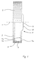
- FIG. 1 shows a flap grinding tool according to the invention, which is symmetrical about an axis of rotation 1 and a Has a plurality of grinding flaps 2 arranged on the circumference.
- the Sanding flaps 2 are in a conventional manner, e.g. B. by means of a Adhesive 3 attached to a carrier body 4a, 4b.
- the carrier body comprises, for example, a deep-drawn one Metal disc 4a, which as a device for connecting the Flap grinding tool with a drive device a hole 5 for Inclusion of a screw fastening of a common drive spindle having.
- a Carrier ring 4b attached in the area of the outer circumference of the metal disc 4a .
- On the outside of the carrier ring 4b is one jacket surface 6 oriented approximately cylindrical to axis of rotation 1 formed on which the adhesive 3 for fastening the grinding flaps 2 is applied, i.e. the lateral surface 6 is approximately 0 ° to the axis of rotation 1 inclined.
- the metal disc 4a comprises a Central element 7, which is essentially radial to the axis of rotation 1 extends.
- a contact surface 8 for contact a drive device.
- the metal disc 4a cranked, resulting in a mechanically particularly stable Execution results.
- the disc 4a is so far cranked that the contact surface 8 axially outside of one by the Outer edges of the grinding lamella 2 circumscribed body is arranged.
- such a tool according to the invention can also be used especially good on hand-held grinders, especially Angle grinders, are used, which extends their scope extended.
- a lamellar grinding tool according to the invention of the carrier body Plastic preferably comprise a fiber-reinforced plastic and / or that the carrier body be made of aluminum or steel. It is advantageous here. if the disc 4a is made of a plastic, preferably a fiber-reinforced plastic, or is made Washer 4a is made of aluminum or steel.
- the carrier ring 4b made of a plastic, preferably a fiber-reinforced plastic, a hard rubber or a hard paper is made, or that the Carrier ring 4b is made of aluminum or steel.
- disc 4a and carrier ring 4b made of weldable materials, e.g. Steel or Aluminum.
- a weld seam for the connection of disc 4a and carrier ring 4b is denoted by 4c, which, depending on the expediency, is circumferential or only can be formed in sections or as spot welding.
- the carrier ring 4b and Washer 4a are made of different materials.
- the carrier ring and disc together are connected by pressing or gluing.
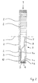
- the flap grinding tool shown in Fig. 2 has for Processing especially of molds in mold making when trying highlighted particularly efficiently.
- grinding flaps 2 are both on the circumference 9, as well as on a front lateral surface 10 of the Flap grinding tool arranged.
- the inventive design allows a simultaneous Circumferential and forehead grinding with comparable performance features both in terms of grinding performance and tool life. Also exists the great advantage over the known tool design that there is practically no risk of slat parts breaking out, since the slats are only stressed in the direction of pull in which they are designed for a corresponding load.
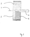
- the lamellar grinding tool shown in Fig. 3 leaves are particularly easy to manufacture because a shaft 11 as a device for connecting the flap grinding tool to a Serves drive device that is rotatably connected to the carrier body is and the carrier body consists of a synthetic resin body 12, in the the grinding flaps 2 and the shaft 11 are directly embedded.
- This is also special with regard to disposal after use advantageous because there is a much easier way of Material separation results and thus the disposal effort is reduced and an at least partial recycling of the components of the Tool is possible.
- the carrier body is through at least partially shedding one between them positioned grinding flaps 2 and the shaft 11 formed space with a plastic or synthetic resin.
- a plastic or synthetic resin has been particularly suitable the use of hard paper (fiber material) emerged.
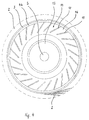
- FIG. 4 shows a particularly advantageous embodiment of the invention shown schematically and partially simplified. This is suitable especially for use on a stationary grinding machine in the Production.
- the grinding flaps are 2 (only a few of them are excellent) as in the other embodiments by means of adhesive 3 on a carrier ring 4b, e.g. advantageously from a hard paper, attached.
- the carrier ring 4b is in operation radially outside by one Centrifugal or eccentric clamping device arranged in place the disc 4a occurs in the other described embodiments.
- This centrifugal force or eccentric clamping device can for example comprise a turned aluminum core 13 which has a hole 5 for receiving a mandrel or otherwise for coupling with a Drive can be designed appropriately.
- the aluminum core 13 or one Corresponding component made of any other suitable material can shaped like a hub.
- Radially around the core 13 is in the Embodiment shown vulcanized a rubber ring 14.
- the Rubber ring 14 has numerous slots 15 from its circumference provided, the slots 15 not to the radially inner edge of the Rubber ring 14 range and are arranged inclined to the radius.
- Flap grinding tool according to the invention in which the at least one the lateral surfaces 6 or 10 approximately parallel to the axis of rotation arranged or inclined up to and including 90 ° to the axis of rotation 1 and the carrier body is a device for connecting the Flap grinding tool with a quick clamping device for Connection of the flap grinding tool to a drive device having.
- the device for connecting the Flap grinding tool adapted with a quick release to part of e.g. in the case of the usual bayonets or To form a bayonet connection.
- Such a connection allows one particularly safe and quick connection of the tool to a The drive and the correct fit of the tool is visually good recognizable.
- An embodiment is also not shown in the figures preferably for stationary operation, where the Flap grinding tool has a large length in the axial direction to form a large grinding width. It is useful if the carrier body has two or more disks 4a in order to ensure good Support of the support ring 4b on the drive shaft and thus one to ensure even removal.
Landscapes
- Engineering & Computer Science (AREA)
- Mechanical Engineering (AREA)
- Polishing Bodies And Polishing Tools (AREA)
Description
- Fig. 1
- ein erfindungsgemäßes Lamellenschleifwerkzeug mit radial angeordneten Schleiflamellen:
- Fig. 2
- ein erfindungsgemäßes Lamellenschleifwerkzeug mit radial und stirnseitig angeordneten Schleiflamellen;
- Fig. 3
- ein Lamellenschleifwerkzeug, bei dem ein Schaft zum Antrieb des Werkzeugs und die Schleiflamellen direkt in einen Kunstharzkörper eingebettet sind;
- Fig. 4
- ein erfindungsgemäßes Lamellenschleifwerkzeug mit radial angeordneten Schleiflamellen, bei dem die Scheibe des Trägerkörpers durch eine selbsttätig wirkende Exzenter- oder Fliehkraftspannvorrichtung gebildet ist (teilweise in schematischer Darstellung).
Claims (11)
- Lamellenschleifwerkzeug, das symmetrisch um eine Rotationsachse(1) ausgebildet ist, mita) einer Vielzahl von auf dem Umfang und/oder Stirnseiten angeordneten Schleiflamellen (2).b) einem Trägerkörper (4a, 4b, 12, 13, 14), auf dem die Schleiflamellen (2) befestigt sind, undc) einer Einrichtung (5, 11) zur Verbindung des Lamellenschleifwerkzeuges mit einer Antriebsvorrichtung,
wobeid) der Trägerkörper (4a, 4b, 12, 13, 14) wenigstens eine rotationssymmetrische Mantelfläche (6, 10) aufweist, auf der die Schleiflamellen (2) zumindest zum Teil befestigt sind,
dadurch gekennzeichnet,e) daß der Trägerkörper (4a, 4b, 12, 13, 14) wenigstens ein als Scheibe (4a) ausgebildetes Zentralelement (7) umfaßt, das sich im wesentlichen radial zur Rotationsachse (1) erstreckt und die Einrichtung zur Verbindung des Lamellenschleifwerkzeuges mit einer Antriebsvorrichtung zumindest eine durch die Scheibe (4a) gebildete Anlagefläche (8) zur Verbindung des Lammellenschleifwerkzeuges mit einer Antriebsvorrichtung aufweist, undf) der Trägerkörper (4a, 4b, 12, 13, 14) ferner einen davon separaten Trägerring (4b) umfaßt, auf dessen radial äußerer Außenseite eine der Mantelflächen (6, 10) annähernd parallel zur Rotationsachse (1) oder zumindest weniger als 75° zur Rotationsachse (1) geneigt gebildet ist, und der Trägerring (4b) und Scheibe (4a) aus verschiedenen Werkstoffen hergestellt sind. - Lamellenschleifwerkzeug, nach Anspruch 1,
dadurch gekennzeichnet, daß
die Scheibe (4a) im Bereich der Anlagefläche (8) so weit gekröpft ist, daß die Anlagefläche (8) axial außerhalb eines durch die Außenkanten der Schleiflamellen (2) umschriebenen Rotationskörpers angeordnet ist. - Lamellenschleifwerkzeug nach einem der vorhergehenden Ansprüche,
dadurch gekennzeichnet, daß
die Scheibe (4a) aus einem Kunststoff, vorzugsweise einem faserverstärkten Kunststoff, aus Aluminium oder aus Stahl hergestellt ist. - Lamellenschleifwerkzeug nach einem der vorhergehenden Ansprüche,
dadurch gekennzeichnet, daß
der Trägerring (4b) aus einem Kunststoff, vorzugsweise einem faserverstärkten Kunststoff, aus einem Hartgummi, aus einem Hartpapier, aus Aluminium oder aus Stahl hergestellt ist. - Lamellenschleifwerkzeug nach einem der vorhergehenden Ansprüche,
dadurch gekennzeichnet, daß
Trägerring (4b) und Scheibe (4a) miteinander durch Einpressen, Kleben oder Schweißen verbunden sind. - Lamellenschleifwerkzeug nach einem der vorhergehenden Ansprüche,
dadurch gekennzeichnet, daß
die Scheibe (4a) durch eine selbsttätig wirkende Exzenter- oder Fliehkraftspannvorrichtung (13, 14, 15, 16) gebildet ist. - Lamellenschleifwerkzeug nach einem der vorhergehenden Ansprüche,
dadurch gekennzeichnet, daß
der Trägerkörper (4a, 4b, 12, 13, 14) mehrere Scheiben (4a) aufweist. - Lamellenschleifwerkzeug nach einem der vorhergehenden Ansprüche,
dadurch gekennzeichnet, daß
Schleiflamellen (2) sowohl auf dem Umfang (9), als auch auf einer Stirnseite (10) des Lamellenschleifwerkzeuges angeordnet sind. - Lamellenschleifwerkzeug nach einem der vorhergehenden Ansprüche,
dadurch gekennzeichnet, daß
der Trägerkörper (4a, 4b, 12, 13, 14) eine Einrichtung zur Verbindung des Lamellenschleifwerkzeuges mit einer Schnellspannvorrichtung zur Verbindung des Lamellenschleifwerkzeuges mit einer Antriebsvorrichtung aufweist. - Lamellenschleifwerkzeug nach Anspruch 9,
dadurch gekennzeichnet, daß
die Einrichtung zur Verbindung des Lamellenschleifwerkzeuges mit einer Schnellspannvorrichtung angepaßt ist, um einen Teil einer Renk- oder Bajonettverbindung zu bilden. - Lamellenschleifwerkzeug nach Anspruch 9,
dadurch gekennzeichnet, daß
die Einrichtung zur Verbindung des Lamellenschleifwerkzeuges mit einer Schnellspannvorrichtung ein ein- oder mehrgängiges Schrauben- oder Muttergewinde umfaßt, wobei das Gewinde ein Steilgewinde, vorzugsweise das Gewinde ein Rechteck- oder Trapezgewinde ist.
Applications Claiming Priority (3)
| Application Number | Priority Date | Filing Date | Title |
|---|---|---|---|
| DE19812515 | 1998-03-21 | ||
| DE19812515A DE19812515A1 (de) | 1998-03-21 | 1998-03-21 | Lamellenschleifwerkzeug |
| PCT/EP1999/001934 WO1999048647A1 (de) | 1998-03-21 | 1999-03-22 | Lamellenschleifwerkzeug |
Publications (2)
| Publication Number | Publication Date |
|---|---|
| EP1068048A1 EP1068048A1 (de) | 2001-01-17 |
| EP1068048B1 true EP1068048B1 (de) | 2004-11-03 |
Family
ID=7861850
Family Applications (1)
| Application Number | Title | Priority Date | Filing Date |
|---|---|---|---|
| EP99916867A Expired - Lifetime EP1068048B1 (de) | 1998-03-21 | 1999-03-22 | Lamellenschleifwerkzeug |
Country Status (4)
| Country | Link |
|---|---|
| US (1) | US6866572B1 (de) |
| EP (1) | EP1068048B1 (de) |
| DE (2) | DE19812515A1 (de) |
| WO (1) | WO1999048647A1 (de) |
Cited By (1)
| Publication number | Priority date | Publication date | Assignee | Title |
|---|---|---|---|---|
| DE102010046878B3 (de) * | 2010-09-29 | 2011-12-15 | Dipl.-Ing. Günter Wendt GmbH | Lamellenschleifwerkzeug |
Families Citing this family (8)
| Publication number | Priority date | Publication date | Assignee | Title |
|---|---|---|---|---|
| DE10042109C2 (de) * | 2000-08-28 | 2003-07-03 | M & F Entw & Patentverwertungs | Polierwerkzeug |
| CN1681510A (zh) * | 2002-09-16 | 2005-10-12 | 爱尔康制造有限公司 | Pde ⅳ抑制剂治疗血管生成的用途 |
| JP5238488B2 (ja) * | 2006-02-20 | 2013-07-17 | 株式会社ジーベックテクノロジー | ブラシ状砥石 |
| DE102008063943A1 (de) | 2008-12-19 | 2010-06-24 | Abb Ag | Werkzeug |
| DE202013105892U1 (de) | 2013-12-20 | 2014-03-13 | Heinrich Kreeb Gmbh & Co. Kg | Schleifkörper |
| US10399207B2 (en) * | 2014-10-27 | 2019-09-03 | Taimei Chemicals Co., Ltd. | Polishing brush |
| DE102015122233A1 (de) * | 2015-12-18 | 2017-06-22 | Thyssenkrupp Ag | Massereduzierter Schleif-Grundkörper |
| EP3434414B1 (de) * | 2017-07-26 | 2025-09-03 | Klingspor AG | Materialbearbeitungsscheibe und verfahren zu ihrer herstellung |
Family Cites Families (16)
| Publication number | Priority date | Publication date | Assignee | Title |
|---|---|---|---|---|
| US938223A (en) * | 1908-09-03 | 1909-10-26 | Robert F Dockery | Machine for making continuous pipes. |
| GB938223A (en) | 1959-10-30 | 1963-10-02 | Rexall Drug Chemical | Abrasive devices |
| US3191208A (en) | 1962-04-19 | 1965-06-29 | George R Churchill Company Inc | Buffing wheel |
| US3406488A (en) | 1965-09-23 | 1968-10-22 | Minnesota Mining & Mfg | Abrasive flap wheel |
| DK16474A (de) | 1974-01-14 | 1975-09-08 | K H Kofoed | |
| US4090333A (en) | 1977-03-25 | 1978-05-23 | Merit Abrasive Products, Inc. | Flexible grinding wheel |
| DE7903893U1 (de) * | 1979-02-13 | 1979-05-17 | Fa. August Rueggeberg, 5277 Marienheide | Rotations-schleifwerkzeug |
| JPS6094271A (ja) | 1983-10-29 | 1985-05-27 | Nippon Rejibon Kk | 回転研削研磨具 |
| DE8523363U1 (de) * | 1985-08-14 | 1985-09-26 | Kemper-Kontakt Gert Kemper GmbH & Co KG, 5600 Wuppertal | Mit Schleiflamellen ausgestatteter Hohlzylinder |
| DE3541347C1 (de) * | 1985-11-22 | 1986-10-30 | Gerd 8192 Geretsried Eisenblätter | Faecherstirnschleifscheibe |
| DE8903423U1 (de) * | 1989-03-18 | 1989-05-03 | Lukas-Erzett Vereinigte Schleif- und Fräswerkzeugfabriken GmbH & Co KG, 5250 Engelskirchen | Schleiflamellenscheibe |
| DE4007928A1 (de) * | 1990-03-13 | 1991-09-19 | Guenther Wendt | Schleifhuelse |
| DE19511004C1 (de) * | 1995-03-25 | 1996-09-19 | Lukas Erzett Schleif Fraes | Werkzeug mit einem Schleif- oder Polierbelag |
| US5637033A (en) * | 1996-02-20 | 1997-06-10 | Williams; Wilson | Flapper wheel adapter |
| US5871399A (en) * | 1996-08-30 | 1999-02-16 | Merit Abrasive Products, Inc. | Flap wheel |
| US5722881A (en) * | 1996-08-30 | 1998-03-03 | Merit Abrasive Products, Inc. | Flap wheel |
-
1998
- 1998-03-21 DE DE19812515A patent/DE19812515A1/de not_active Withdrawn
- 1998-03-22 US US09/646,745 patent/US6866572B1/en not_active Expired - Fee Related
-
1999
- 1999-03-22 WO PCT/EP1999/001934 patent/WO1999048647A1/de not_active Ceased
- 1999-03-22 DE DE59910996T patent/DE59910996D1/de not_active Expired - Lifetime
- 1999-03-22 EP EP99916867A patent/EP1068048B1/de not_active Expired - Lifetime
Cited By (2)
| Publication number | Priority date | Publication date | Assignee | Title |
|---|---|---|---|---|
| DE102010046878B3 (de) * | 2010-09-29 | 2011-12-15 | Dipl.-Ing. Günter Wendt GmbH | Lamellenschleifwerkzeug |
| WO2012052090A1 (de) | 2010-09-29 | 2012-04-26 | Günter Wendt Gmbh | Lamellenschleifwerkzeug |
Also Published As
| Publication number | Publication date |
|---|---|
| DE59910996D1 (de) | 2004-12-09 |
| WO1999048647A1 (de) | 1999-09-30 |
| DE19812515A1 (de) | 1999-09-23 |
| US6866572B1 (en) | 2005-03-15 |
| EP1068048A1 (de) | 2001-01-17 |
Similar Documents
| Publication | Publication Date | Title |
|---|---|---|
| DE10106979A1 (de) | Einsatzwerkzeug mit einer rotierend antreibbaren, scheibenförmigen Nabe | |
| DE3416186A1 (de) | Schleifscheibe | |
| AT502285B1 (de) | Trennschleifring mit doppelter kernspannvorrichtung | |
| WO2002070205A1 (de) | Einsatzwerkzeug mit einer rotierend antreibbaren, scheibenförmigen nabe | |
| DE69805277T2 (de) | Notlaufvorrichtung für auto und verfahren zu seiner montage | |
| EP1068048A1 (de) | Lamellenschleifwerkzeug | |
| EP1313594B1 (de) | Polierwerkzeug | |
| EP0612586B1 (de) | Schleifscheibe für handgeführte Schleifmaschinen, insbesondere Trenn-Schleifscheibe | |
| EP1543923B1 (de) | Schrupp-Schleifscheibe | |
| EP2440371B1 (de) | Schleif- und/oder polierwerkzeug und herstellungsverfahren | |
| EP1174219B1 (de) | Schleifwerkzeug | |
| DE2325033B2 (de) | Rad | |
| DE20006127U1 (de) | Schleiflamelle und Schleifteller mit einer Mehrzahl von solchen | |
| EP1050377B1 (de) | Rotierendes Maschinen-Schleifwerkzeug | |
| DE202007007839U1 (de) | Lamellenschleifscheibe | |
| DE29510727U1 (de) | Werkzeug, insbesondere Schleif- oder Polierteller | |
| DE69117058T2 (de) | Verfahren zum herstellen von oberflächen fertigbearbeitungsrollen sowie auf diese weise herrgestellte rolle | |
| AT509372B1 (de) | Verbundschleifsystem | |
| EP0657251B1 (de) | Trenn-Schleifscheibe für stationäre Schleifmaschinen und deren Verwendung | |
| DE3323409C1 (de) | Sägeblatt | |
| DE19511004C1 (de) | Werkzeug mit einem Schleif- oder Polierbelag | |
| DE102010046878B3 (de) | Lamellenschleifwerkzeug | |
| DE69007467T2 (de) | Doppelseitige Schleifscheibe mit interner Verstärkung. | |
| WO1984003467A1 (fr) | Dispositif transportable pour la reprise des deux faces de disques de frein uses de vehicules automobiles | |
| DE102004028529A1 (de) | Werkzeugaufnahmevorrichtung für ein Einsatzwerkzeug |
Legal Events
| Date | Code | Title | Description |
|---|---|---|---|
| PUAI | Public reference made under article 153(3) epc to a published international application that has entered the european phase |
Free format text: ORIGINAL CODE: 0009012 |
|
| 17P | Request for examination filed |
Effective date: 20001019 |
|
| AK | Designated contracting states |
Kind code of ref document: A1 Designated state(s): DE FR GB IT |
|
| 17Q | First examination report despatched |
Effective date: 20010124 |
|
| GRAP | Despatch of communication of intention to grant a patent |
Free format text: ORIGINAL CODE: EPIDOSNIGR1 |
|
| GRAS | Grant fee paid |
Free format text: ORIGINAL CODE: EPIDOSNIGR3 |
|
| GRAA | (expected) grant |
Free format text: ORIGINAL CODE: 0009210 |
|
| AK | Designated contracting states |
Kind code of ref document: B1 Designated state(s): DE FR GB IT |
|
| REG | Reference to a national code |
Ref country code: GB Ref legal event code: FG4D Free format text: NOT ENGLISH |
|
| RAP2 | Party data changed (patent owner data changed or rights of a patent transferred) |
Owner name: DIPL.-ING. GUENTER WENDT GMBH |
|
| REF | Corresponds to: |
Ref document number: 59910996 Country of ref document: DE Date of ref document: 20041209 Kind code of ref document: P |
|
| GBT | Gb: translation of ep patent filed (gb section 77(6)(a)/1977) |
Effective date: 20050331 |
|
| PLBE | No opposition filed within time limit |
Free format text: ORIGINAL CODE: 0009261 |
|
| STAA | Information on the status of an ep patent application or granted ep patent |
Free format text: STATUS: NO OPPOSITION FILED WITHIN TIME LIMIT |
|
| 26N | No opposition filed |
Effective date: 20050804 |
|
| ET | Fr: translation filed | ||
| REG | Reference to a national code |
Ref country code: DE Ref legal event code: R082 Ref document number: 59910996 Country of ref document: DE Representative=s name: LUEDCKE, JOACHIM MORITZ, DIPL.-ING., DE Ref country code: DE Ref legal event code: R082 Ref document number: 59910996 Country of ref document: DE Representative=s name: JOACHIM MORITZ LUEDCKE, DE |
|
| REG | Reference to a national code |
Ref country code: FR Ref legal event code: PLFP Year of fee payment: 17 |
|
| REG | Reference to a national code |
Ref country code: FR Ref legal event code: PLFP Year of fee payment: 18 |
|
| PGFP | Annual fee paid to national office [announced via postgrant information from national office to epo] |
Ref country code: GB Payment date: 20160223 Year of fee payment: 18 |
|
| PGFP | Annual fee paid to national office [announced via postgrant information from national office to epo] |
Ref country code: IT Payment date: 20160324 Year of fee payment: 18 |
|
| REG | Reference to a national code |
Ref country code: DE Ref legal event code: R082 Ref document number: 59910996 Country of ref document: DE Representative=s name: LUEDCKE, JOACHIM MORITZ, DIPL.-ING., DE Ref country code: DE Ref legal event code: R081 Ref document number: 59910996 Country of ref document: DE Owner name: GUENTER WENDT GMBH, DE Free format text: FORMER OWNER: DIPL.-ING. GUENTER WENDT GMBH, 51570 WINDECK, DE |
|
| REG | Reference to a national code |
Ref country code: FR Ref legal event code: PLFP Year of fee payment: 19 |
|
| GBPC | Gb: european patent ceased through non-payment of renewal fee |
Effective date: 20170322 |
|
| PG25 | Lapsed in a contracting state [announced via postgrant information from national office to epo] |
Ref country code: IT Free format text: LAPSE BECAUSE OF NON-PAYMENT OF DUE FEES Effective date: 20170322 Ref country code: GB Free format text: LAPSE BECAUSE OF NON-PAYMENT OF DUE FEES Effective date: 20170322 |
|
| REG | Reference to a national code |
Ref country code: FR Ref legal event code: PLFP Year of fee payment: 20 |
|
| PGFP | Annual fee paid to national office [announced via postgrant information from national office to epo] |
Ref country code: DE Payment date: 20180307 Year of fee payment: 20 |
|
| PGFP | Annual fee paid to national office [announced via postgrant information from national office to epo] |
Ref country code: FR Payment date: 20180323 Year of fee payment: 20 |
|
| REG | Reference to a national code |
Ref country code: DE Ref legal event code: R071 Ref document number: 59910996 Country of ref document: DE |