EP1050382A2 - Gelenk für ein Werkzeug - Google Patents
Gelenk für ein Werkzeug Download PDFInfo
- Publication number
- EP1050382A2 EP1050382A2 EP00108419A EP00108419A EP1050382A2 EP 1050382 A2 EP1050382 A2 EP 1050382A2 EP 00108419 A EP00108419 A EP 00108419A EP 00108419 A EP00108419 A EP 00108419A EP 1050382 A2 EP1050382 A2 EP 1050382A2
- Authority
- EP
- European Patent Office
- Prior art keywords
- joint according
- swivel
- receptacle
- ring
- joint
- Prior art date
- Legal status (The legal status is an assumption and is not a legal conclusion. Google has not performed a legal analysis and makes no representation as to the accuracy of the status listed.)
- Withdrawn
Links
Images



Classifications
-
- B—PERFORMING OPERATIONS; TRANSPORTING
- B25—HAND TOOLS; PORTABLE POWER-DRIVEN TOOLS; MANIPULATORS
- B25B—TOOLS OR BENCH DEVICES NOT OTHERWISE PROVIDED FOR, FOR FASTENING, CONNECTING, DISENGAGING, OR HOLDING
- B25B23/00—Details of, or accessories for, spanners, wrenches, screwdrivers
- B25B23/0007—Connections or joints between tool parts
- B25B23/0028—Angular adjustment means between tool head and handle
-
- B—PERFORMING OPERATIONS; TRANSPORTING
- B25—HAND TOOLS; PORTABLE POWER-DRIVEN TOOLS; MANIPULATORS
- B25B—TOOLS OR BENCH DEVICES NOT OTHERWISE PROVIDED FOR, FOR FASTENING, CONNECTING, DISENGAGING, OR HOLDING
- B25B23/00—Details of, or accessories for, spanners, wrenches, screwdrivers
- B25B23/0007—Connections or joints between tool parts
- B25B23/0014—Screwdriver- or wrench-heads provided with cardan joints or the like
-
- B—PERFORMING OPERATIONS; TRANSPORTING
- B25—HAND TOOLS; PORTABLE POWER-DRIVEN TOOLS; MANIPULATORS
- B25B—TOOLS OR BENCH DEVICES NOT OTHERWISE PROVIDED FOR, FOR FASTENING, CONNECTING, DISENGAGING, OR HOLDING
- B25B23/00—Details of, or accessories for, spanners, wrenches, screwdrivers
- B25B23/0007—Connections or joints between tool parts
- B25B23/0035—Connection means between socket or screwdriver bit and tool
Definitions
- the invention has for its object a possibility to create how to transfer torque even under difficult working conditions can be eased.
- the invention proposes a joint with the features of claim 1. Further training of the Invention are the subject of the dependent claims, the Wording as well as the wording of the summary Reference is made to the content of the description.
- the joint is between the tool with which the torque is applied, and the object to which the Torque should be transmitted.
- That Joint between a screwdriver and the screw used.
- the recording is made with the tool or Workpiece connected while the pivoting element with the each other element is connected.
- the drive axis that is, the axis around which the tool is rotated is not must coincide more with the axis of the workpiece.
- the joint can be handled very easily because by the tendency of the joint to pass through the two axes Provision of the pivot element to align the joint is straightened when not in use.
- the receptacle has a cavity that over part of its length has a polygonal cross section, the pivot element also over part of its Length a polygonal cross-section matched to it having.
- This kind of training the two of each other matched parts is one of several ways to to ensure that the two parts in the direction of rotation are non-rotatably connected.
- the walls of the cavity the recording in the polygonal area evenly formed are. This makes the joint easy to manufacture.
- the swivel element a convex longitudinal section in its polygonal area having. Rolls when pivoting the swivel element or then slide it open with its convex outer sides the walls of the recording.
- the walls of the Recording have a matching shape, so that a Sliding of two spherical surfaces occurs on each other.
- the joint can be easily designed if that Reset element is designed and arranged such that it not only tries to straighten the swivel element, but also acted on the recording.
- the reset element takes on a second function.
- the restoring element is under force, it can also be designed so that the swivel element can be removed from the recording becomes possible.
- the Reset element is a separate part that is attached to one of the both parts, in particular on the recording, is supported and can be moved towards this.
- the reset element can be particularly favorable to the shape and Function of the swivel element can be adjusted.
- the end of the Swivel elements the bottom of the receptacle or the cavity touched, at least in the neutral position, preferably in any position of the swivel joint. It is with drive tools known to use magnets that hold the screw hold in front of and at the beginning of screwing in. Through the Contact between the pivoting element and the bottom of the A magnet can be accommodated in the device not through an air gap from the screw is separated.
- the contact between the swivel element and the receptacle in all positions, if possible it is provided in a further development that the the receptacle facing the end of the swivel element is convex, the radius of curvature on the The center of the swivel movement of the swivel element is matched is.
- the pivot element can, for example, in the axial direction attack at the end of the swivel element. Very cheap it is, however, if the restoring element is located approximately radially on the Swivel element between the free end and the through the convex surfaces attacks certain pivot bearings. Thereby is achieved with a compact structure of the joint the radial point of the decrease or introduction of force not changed too much.
- the joint may be sufficient if the joint is a has only reset element. It is particularly cheap however, if the joint has at least two return elements has distributed over the circumference on the pivoting element attack, especially evenly distributed over the circumference.
- an approximately tangential pin is used will be straight or curved can.
- a curved spigot which is also called a bow piece could denote the concave side of the curvature to the swivel element.
- a ball which is approximately radial Hole is arranged. In this case, it makes sense to use at least three balls.
- the Swivel element has a circumferential groove in which the Intervene reset elements, it may be sufficient when the return elements engage the bottom of the groove to straighten the pivoting element, and on a flank of the Groove to the reset element into the receptacle act upon.
- the reset element can, for example, according to the invention under the action of a tensioned spring.
- Other Opportunities are particularly with machine tools also possible.
- the spring action by an O-ring be generated. This is an inexpensive one easy to use and easy to replace Component.
- the O-ring is under Tension is inserted in a circumferential groove and thereby the restoring elements acted upon.
- the spring action serves So both for loading the reset elements as well to fix the O-ring.
- the groove is such is formed that the O-ring to the outside over the sides which protrudes the surfaces delimiting the groove. It will possible to influence the O-ring from the outside, too for example to compress. Through this additional It can compress the already tensioned O-ring Force with which the return elements on the swivel element act, be enlarged, for example in machine tools can be useful.
- This sleeve can be moved so that it is the O-ring somewhat compressed.
- the then compressed serves O-ring also prevents the sleeve from being accidentally Secure move.
- the Reset element consists of compressible material or has compressible material.
- the reset element especially when it consists at least partially of compressible material, in radial direction between the inside of the receptacle and the pivot element is arranged.
- the restoring element by one Compression ring made of elastomer material educated. is what can be provided according to the invention.
- the Ring does not have to be fully formed, it Rather, it can also be sufficient if it consists of individual longitudinal a ring arranged pieces or parts.
- the joint proposed by the invention can be a part of a hand tool, i.e. directly in a screwdriver be installed.
- the joint can also be part of a machine screwdriver his.
- the joint be formed as a separate part is, for example, with a drive tool standardized facility can be connected while the opposite end can be connected with a bit can.
- the invention also proposes several joints to one Combine component to create a larger swivel angle to enable.
- Figure 1 shows the front area partially cut for example, a screwdriver with a joint a first embodiment of the invention.
- a receptacle 1 formed in the embodiment shown has a cavity 2, the to the front 3 of the component is open and inside of one flat floor 4 is limited.
- the cavity 2 In its front 3 adjacent area, the cavity 2 has a polygonal, for example octagonal cross-section with flat inner walls 5 on. At this area with the cross section of a prism closes an area 6 with a circular cross section on.
- a swivel element 10 is in the receptacle 1 used that in its the area with the flat side walls 5 corresponding area in cross section as well is polygonal.
- the outer walls 11th in the form of an arc. This creates a joint which is rotationally fixed in the direction of rotation during a pivoting by sliding the arcuate outer walls 11 of the Swivel elements 10 on the flat walls 5 of the recording is possible.
- the pivot bearing is located outside the component, in which the receptacle 1 is formed, a section 16 enlarged Diameter.
- the front end of the swivel element 10 is formed by a square neck 17, for example can be used in an extension for a tool.
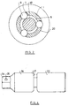
- FIG. 2 shows a cross section through the joint of FIG. 1 at the level of the holes 7. These holes 7 run radially. In each bore 7, a ball 9 is inserted, which one Diameter of the bore 7 has approximately the same diameter. Due to the narrowing mentioned with reference to FIG. 1 8 of the diameter of the bore 7 ensures that the Balls 9 do not fall inwards into the receptacle can, if the pivot member 10 is not used.
- the holes 7 open on the outside of the receptacle 1 having component in an annular groove in which an O-ring is inserted.
- This O-ring 18 is shown in Figure 1.
- the O-ring acts on all balls 9 radially inwards, so that they're all with the same force at the bottom of the section 12 of the swivel element 10 rest. Through this Force that acts evenly on all balls 9 becomes Centered pivot element 10 and thus aligned, so that the axis of the receptacle 1 with the axis of the square 17th coincides.
- the O-ring is dimensioned so that it is in the groove is under tension.
- the front inner edge 22 of the sleeve 21 is slightly chamfered.
- the sleeve 21 is shown from its left in Figure 1 inactive position in which it is held by a spring washer 23 is secured, moved, so the front inner edge slides 22 of the sleeve 21 on the outside of the O-ring 18 and compresses it into the groove and thus against the Sphere 9.
- This position is shown on the right in FIG. 2, here also the spring ring 23 by engaging in a Inner groove 24 allows a determination.
- By moving the Sleeve 21 causes an increase in the force with which the restoring elements, namely the balls 9, the pivoting element 10 straighten. This enlargement can in particular then be of advantage if the joint with a very fast rotating machine tool is used to the acting on the balls 9 when rotating Compensate centrifugal forces.
- the sleeve 20 is in the illustrated embodiment slidably supported on the tool. Yours with the o-ring 18 co-operating inside runs coaxially to the longitudinal axis of the tool. It is also possible and is supported by the Invention proposed that this inner wall in the direction increasing displacement is divergent, so that the pre-compression of the O-ring 18 increases Shift also increases. This will make it possible Force with which the swivel element 10 is being straightened to change. In this case, it makes sense to use the sleeve 21 not to be designed as a sliding sleeve, but with the help of a Attach thread to the tool. It can then be essential can be adjusted more finely.
- the Balls 9 also on the arcuate shoulder 13 between the Part 12 and the ring 14. They also cause one Force component in the direction of the axis that the pivot element 10 loaded into the receptacle 1. This will make a Falling out of the pivot element 10 from the receptacle 1 prevented.
- the pivot member 10 With sleeve 21 pushed up, left in Figure 1, the pivot member 10 can be removed by pulling as the balls 9 then against the O-ring to the outside can be moved.
- FIG. 3 shows one possibility of how several joints according to the invention can be combined to form a component which can be used in a drive train between a tool and a workpiece.
- the component of FIG. 3 contains at one end a hexagonal extension 30 which is removably held in a receptacle 31.
- a sleeve-like element 32 is arranged, which has a hexagonal inner opening for receiving it contains elements in the form of the approach 30.
- Several joints are arranged between the two parts, so that the possible pivot angles of each individual joint add up.
- FIG. 4 shows a further possibility of how a joint proposed by the invention can be used.
- a square neck 34 is formed, in one side surface of which a spring ball 35 is inserted.
- the square attachment is followed by a first receptacle 36 in which, for example, a swivel joint according to FIG. 1 is accommodated.
- the swivel element protrudes from the end face 37 of the receptacle 36 and engages in a second receptacle 36 in which this swivel element is inserted again in a receptacle.
- a square opening goes into the receptacle 36, which is the same shape and size as your square shoulder 34.
- This component shown in FIG. 4 can be used, for example, between a drive tool and a nut.
- Swivel element 10 simultaneously as a swivel element for two recordings.
- FIG. 5 is a longitudinal section through the front Part of a tool similar to Figure 1 shows.
- the tool also contains a receptacle 1, which is of similar design is like the receptacle 1 of the embodiment of FIGS. 1 and 2.
- the receptacle contains a cavity 2 that faces inwards is completed by a flat floor 4. From the floor 4 starting out, an area closes with a circular cross-sectional shape, so that the inner wall 6 of the Cavity 2 forms the wall of a circular cylinder. This wall could also be a little divergent.
- the pivotable element inserted in the receptacle is constructed exactly as in Figure 1, so that it is also not is described more.
- a O-ring 40 made of compressible elastomer material. Due to the transition between the polygonal cross section and the circular cross section is at least in some places of the cavity 2 is an inward projection 41 formed, which prevents the O-ring 40 from slipping out.
- the O-ring 40 can if the workpiece has not yet been inserted is to be inserted into the recording so that it is a has certain outward tension.
- the O-ring 40 is between the wall 6 of the cavity and the Swivel element in the area of its groove 12 in the starting position already somewhat compressed. Similar to that Balls 9 in the embodiment of FIG. 1 secures the O-ring the element used against falling out and straighten it out. If one of a rotational symmetry of the Cavity 2 and the part of the inserted into the receptacle 1 Pivot element, this is through the O-ring 40th straightened.
- the cross section through the tool of FIG. 5 in FIG. 6 shows that the O-ring 40 as a reset element on the inner wall 6 of the cavity 2 abuts on all sides, and that the O-ring 40, as is usual with O-rings, the same everywhere Has thickness. This creates a coaxial interior 42 formed in which the pivoting element 10 used Swivel section 12 is arranged.
- the tool shown in Figs. 5 and 6 is assembled so that first inserted into the receptacle of the O-ring 40 becomes. Then the pivot element 10 can be axially be inserted. The ring 14 compresses the O-ring 40 so far that the tool to the bottom 4 of the cavity 2nd reached. Then the O-ring 40 lies between the pivoting section and the inner wall 6 of the cavity.
- the possibility mentioned in the embodiment according to FIG. 1 The restoring torque can be changed here can be realized that another O-ring 40 is used with either a different modulus of elasticity or with another cross section. It is also conceivable to attach the O-ring to attach section 12 captively, for example to vulcanize.
- Figure 7 shows another possibility, such as a pivoting element 10 'can be formed, according to the invention can form part of a swivel joint.
- the swivel element 10 'of Figure 7 contains two identically constructed Hinge parts that are joined together by a short section 16 are connected. This makes it possible, for example, to front part of a screwdriver, similar to Figure 1 or Fig. 5, to install such a pivoting element, and then a plug on further component. Such a continuation
- the component is partially cut in FIG. 8 shown. It contains a picture on one side 1, similar to the tool of Figures 5 and 6, and on it on the other side an output element in the form of a square 34.
- the element shown in Figure 8 can with the help of a 7 on the hand tool or be attached to a machine tool. This enlarges the possible swivel angle.
- Figure 9 shows another element at one end integrally or firmly connected to the swivel part of a Has pivoting elements while at the other end Square 34 is attached.
- This square can be similar to be firmly attached to the element of Figure 8 or in be a recess recorded from which it is removed can be.
- Combinations of such elements can of course also be used can be used, for example an element on both Each end has a receptacle 1 for a swivel joint, practically the counterpart to the element of the figure 7.
- a connecting element is also possible one end face a receptacle 1 and the other Side has the pivot part of a pivot element.
Landscapes
- Engineering & Computer Science (AREA)
- Mechanical Engineering (AREA)
- Details Of Spanners, Wrenches, And Screw Drivers And Accessories (AREA)
- Pivots And Pivotal Connections (AREA)
- Dental Tools And Instruments Or Auxiliary Dental Instruments (AREA)
Abstract
Description
- Fig. 1
- einen Schnitt durch ein von der Erfindung vorgeschlagenes Gelenk;
- Fig. 2
- einen Querschnitt etwa längs Linie II-II in Fig. 1;
- Fig. 3
- eine Ausführungsform der Erfindung, bei der mehrere Elemente mit jeweils einem Schwenkgelenk zu einem Bauteil zusammen gefasst sind;
- Fig. 4
- ein von der Erfindung vorgeschlagenes Gelenk als Zwischenteil zwischen einem Antriebswerkzeug und einem Antrieb.
- Figur 5
- eine der Fig. 1 entsprechende Darstellung einer weiteren Ausführungsform;
- Fig. 6
- einen Querschnitt durch das Werkzeug der Figur 5 längs Linie VI-VI in Fig. 5;
- Fig. 7
- ein Verbindungselement als Teil einer Ausrüstung;
- Fig. 8
- ein weiteres mit der Erfindung verwendbares Werkzeugelement;
- Fig. 9
- eine Seitenansicht eines weiteren Verbindungselements nach der Erfindung.
es Elements in der Form des Ansatzes 30 enthält. Zwischen den beiden Teilen sind jeweils mehrere Gelenke angeordnet, so dass sich die mögliche Schwenkwinkel jedes einzeln Gelenks addieren.
Schwenkelement 10 gleichzeitig als Schwenkelement für zwei Aufnahmen.
Claims (29)
- Gelenk für ein Werkzeug zum Übertragen eines Drehmoments, mit1.1 einer Aufnahme (1),1.2 einem in die Aufnahme (1) eingesetzten Schwenkelement (10), das1.2.1 in Drehrichtung um die Antriebsachse/Abtriebsachse des Werkzeugs drehtest und1.2.2 aus der Antriebs-bzw. Abtriebsachse heraus schwenkbar gehaltert ist,1.3 mindestens einem Rückstellelement, das1.3.1 zwischen der Aufnahme (1) und dem Schwenkelement (10) wirksam ist,1.3.2 unter Krafteinwirkung steht und1.3.3 das Schwenkelement (10) geradezurichten versucht.
- Gelenk nach Anspruch 1, bei dem die Aufnahme (1) einen Hohlraum (2) aufweist, der über einen Teil seiner Länge einen mehreckigen Querschnitt aufweist, und bei dem das Schwenkelement (10) über einen Teil seiner Länge einen darauf abgestimmten mehreckigen Querschnitt aufweist.
- Gelenk nach Anspruch 1 oder 2, bei dem die Wände (5) des Hohlraums (2) der Aufnahme (1) in dem mehreckigen Bereich eben sind.
- Gelenk nach einem der vorhergehenden Ansprüche, bei dem das Schwenkelement (10) in seinem mehreckigen Bereich einen konvexen Längsschnitt aufweist.
- Gelenk nach einem der vorhergehenden Ansprüche, bei dem das Rückstellelement das Schwenkelement (10) in die Aufnahme (1) hinein beaufschlagt.
- Gelenk nach einem der vorhergehenden Ansprüche, bei dem das Rückstellelement ein separates Teil ist, das an der Aufnahme (1) gehaltert und dieser gegenüber bewegbar ist.
- Gelenk nach einem der vorhergehenden Ansprüche, bei dem das in die Aufnahme (1) hinein gerichtete Ende des Schwenkelements (10) den Boden (4) der Aufnahme (1) berührt.
- Gelenk nach einem der vorhergehenden Ansprüche, bei dem das in die Aufnahme (1) hinein gerichtete Ende des Schwenkelements (10) konvex ausgebildet ist.
- Gelenk nach einem der vorhergehenden Ansprüche, bei dem das Rückstellelement an dem Schwenkelement (10) zwischen dessen freiem Ende und dem Schwenklager angreift.
- Gelenk nach einem der vorhergehenden Ansprüche, mit mindestens zwei Rückstellelementen, die über den Umfang verteilt an dem Schwenkelement (10) angreifen.
- Gelenk nach einem der vorhergehenden Ansprüche, bei dem das Rückstellelement eine Kugel (9) ist, die in einer etwa radial verlaufenden Bohrung (7) angeordnet ist.
- Gelenk nach einem der Ansprüche 1 bis 10, bei dem das Rückstellelement ein etwa tangential verlautender Zapfen ist.
- Gelenk nach einem der Ansprüche 1 bis 10, bei dem das Rückstellelement ein etwa tangential verlaufendes Bogenstück ist.
- Gelenk nach einem der vorhergehenden Ansprüche, bei dem das Rückstellelement in einer Umfangsnut des Schwenkelements (10) angreift.
- Gelenk nach einem der vorhergehenden Ansprüche, bei dem das Rückstellelement unter Federwirkung steht.
- Gelenk nach Anspruch 15, bei dem die Federwirkung durch einen O-Ring (18) erzeugt wird.
- Gelenk nach Anspruch 16, bei dem der O-Ring (18) unter Spannung in einer Nut angeordnet ist.
- Gelenk nach Anspruch 16 oder 17, bei dem die Außenkontur des O-Rings (18) nach außen übersteht.
- Gelenk nach einem der Ansprüche 15 bis 18, mit einer Einrichtung zum Verändern der Federwirkung.
- Gerät nach Anspruch 19, bei dem die Einrichtung den O-Ring (18) komprimiert.
- Gelenk nach Anspruch 19, mit einer axial verlagerbaren, insbesondere verschiebbaren Hülse (21), die den O-Ring (18) komprimiert.
- Gelenk nach Anspruch 21, bei dem die Komprimierung des O-Rings (18) mit stärkerer Verlagerung der Hülse (21) zunimmt.
- Gelenk nach einem der vorhergehenden Ansprüche, bei dem das Rückstellelement mindestens teilweise aus komprimierbarem Material besteht.
- Gelenk nach Anspruch 23, bei dem das Rückstellelement in radialer Richtung zwischen der Innenwand (6) der Aufnahme (1) und dem Schwenkelement angeordnet ist.
- Gelenk nach Anspruch 23 oder 24, bei dem das Rückstellelement von einem auf Kompression beanspruchten Ring (40) aus Elastomermaterial gebildet ist.
- Gelenk nach einem der vorhergehenden Ansprüche, als Teil eines Handwerkzeugs.
- Gelenk nach einem der Ansprüche 1 bis 25, als Teil eines Maschinenschraubers.
- Gelenk nach einem der vorhergehenden Ansprüche, als Zwischenteil ausgebildet.
- Gelenk nach einem der vorhergehenden Ansprüche, mit einem weiteren Gelenk zusammen gefasst.
Applications Claiming Priority (2)
| Application Number | Priority Date | Filing Date | Title |
|---|---|---|---|
| DE19920544 | 1999-05-05 | ||
| DE19920544A DE19920544C2 (de) | 1999-05-05 | 1999-05-05 | Gelenk für ein Werkzeug |
Publications (2)
| Publication Number | Publication Date |
|---|---|
| EP1050382A2 true EP1050382A2 (de) | 2000-11-08 |
| EP1050382A3 EP1050382A3 (de) | 2001-10-17 |
Family
ID=7906966
Family Applications (1)
| Application Number | Title | Priority Date | Filing Date |
|---|---|---|---|
| EP00108419A Withdrawn EP1050382A3 (de) | 1999-05-05 | 2000-04-18 | Gelenk für ein Werkzeug |
Country Status (4)
| Country | Link |
|---|---|
| EP (1) | EP1050382A3 (de) |
| JP (1) | JP2000354978A (de) |
| DE (1) | DE19920544C2 (de) |
| TW (1) | TW436387B (de) |
Families Citing this family (5)
| Publication number | Priority date | Publication date | Assignee | Title |
|---|---|---|---|---|
| ATE532473T1 (de) * | 2004-03-26 | 2011-11-15 | Synthes Gmbh | Knochenschraube mit gelenk |
| TWI395643B (zh) * | 2010-01-28 | 2013-05-11 | Cheng Chia Peng | 可更換不同工具組件之萬向接頭(二) |
| TW201307002A (zh) * | 2011-08-08 | 2013-02-16 | Hui-Feng Huang | 萬向扳手結構 |
| TW201420911A (zh) * | 2012-11-16 | 2014-06-01 | Honiton Ind Inc | 萬向接頭結構 |
| JP5822906B2 (ja) * | 2013-12-26 | 2015-11-25 | 柳下技研株式会社 | ポリッシングヘッド |
Family Cites Families (15)
| Publication number | Priority date | Publication date | Assignee | Title |
|---|---|---|---|---|
| US2499569A (en) * | 1945-12-14 | 1950-03-07 | Sara W Cooley | Spring aligned universal joint socket wrench |
| DE827780C (de) * | 1949-12-20 | 1952-01-14 | Max Forst | Steckschluessel mit zum Maul winklig einstellbarem Schaft |
| US2550635A (en) * | 1950-02-10 | 1951-04-24 | Res Eng & Mfg | Self-adjusting bit and holder |
| US3897703A (en) * | 1974-02-08 | 1975-08-05 | Olin G Phipps | Universal socket |
| DE2654877C3 (de) * | 1976-12-03 | 1981-11-19 | Klaus, Frank A., Fullerton, Calif. | Gleichlaufdrehgelenk |
| US4188801A (en) * | 1978-07-03 | 1980-02-19 | Ingersoll-Rand Company | Universal joint |
| DE2934428A1 (de) * | 1979-08-25 | 1981-03-26 | Wera-Werk Hermann Werner Gmbh & Co, 42349 Wuppertal | Spannfutter fuer werkzeug-einsatzstuecke, insbesondere schraubendreherbits |
| DE3820898A1 (de) * | 1988-05-09 | 1989-11-23 | Lorenz Stoeger | Schraubvorrichtung |
| IT1245285B (it) * | 1991-03-20 | 1994-09-13 | Fossati Onorina | Vite per serraggi di precisione e chiave di manovra per tale vite |
| US5069569A (en) * | 1991-05-09 | 1991-12-03 | Ferro Tools Inc. | Universal joint |
| US5738586A (en) * | 1994-09-09 | 1998-04-14 | Consolidated Devices Inc. | Semi-universal torque coupling |
| DE19509909C2 (de) * | 1995-03-18 | 1997-03-20 | Ko Ken Tool Co | Verbindungsanordnung |
| AU5214996A (en) * | 1995-05-12 | 1996-11-21 | Matricbrook Pty Ltd | Power driven ratchet wrench |
| DE19602069A1 (de) * | 1996-01-20 | 1997-07-24 | Schmidt Ulrich Ush Schraubwerk | Schraubendreherbit und Werkzeug zu seiner Anwendung |
| DE29708961U1 (de) * | 1997-05-21 | 1997-07-17 | Hsieh, Chih-Ching, Fong Yuan, Taichung | Gelenk-Steckschlüssel |
-
1999
- 1999-05-05 DE DE19920544A patent/DE19920544C2/de not_active Expired - Fee Related
-
2000
- 2000-04-18 EP EP00108419A patent/EP1050382A3/de not_active Withdrawn
- 2000-04-26 TW TW089107874A patent/TW436387B/zh active
- 2000-05-01 JP JP2000132436A patent/JP2000354978A/ja active Pending
Also Published As
| Publication number | Publication date |
|---|---|
| EP1050382A3 (de) | 2001-10-17 |
| TW436387B (en) | 2001-05-28 |
| JP2000354978A (ja) | 2000-12-26 |
| DE19920544C2 (de) | 2001-06-07 |
| DE19920544A1 (de) | 2000-11-16 |
Similar Documents
| Publication | Publication Date | Title |
|---|---|---|
| DE60104177T2 (de) | Spindeleinheit für Lochsäge und Bohrer | |
| DE60008349T2 (de) | Lösbare schnellverschlussverbindung für eine teleskopische welle | |
| EP2178675B1 (de) | Schnellwechselsystem | |
| DE60102145T2 (de) | Antriebsköpfe für befestigungselemente | |
| DE102010062565B4 (de) | Winkelverstellbarer Handgriff für ein Handwerkzeug | |
| DE202010004425U1 (de) | Kabelverschraubung mit Klemmeinrichtung für eine Armierung des Kabels | |
| DE102019118338B4 (de) | Drehmoment-Antriebskopf | |
| EP3046731A1 (de) | Steckschlüssel | |
| EP0827796A1 (de) | Löseeinheit | |
| DE29809229U1 (de) | Bolzen | |
| DE19920544C2 (de) | Gelenk für ein Werkzeug | |
| EP0817704B1 (de) | Futter mit kupplung | |
| DE2953734C1 (de) | Einrichtung zum Festziehen von Grobgewindeverbindungen | |
| EP1122032B1 (de) | Spannfutter für Schaftenden von Werkzeugseinsatzstücken, insbesondere Schraubendreherbits | |
| DE202012001737U1 (de) | Konstruktion einer einstellbaren Buchse | |
| DE102014219369B4 (de) | Vorrichtung für ein Ausbohren eines nicht lösbaren mechanischen Verbindungselementes, insbesondere einer Nietverbindung | |
| DE3429558C2 (de) | ||
| DE2344621A1 (de) | Vorrichtung zum aufschrauben einer mutter mit innengewinde auf ein mit einem aussengewinde versehenes glied | |
| DE102010003842A1 (de) | Anordnung zur Anbringung eines Bohrers | |
| EP2599644B1 (de) | Kugelrollen-Bauteil mit rastbarer Lagereinrichtung | |
| DE29912708U1 (de) | Schraubwerkzeug zum Eindrehen von Gewindebolzen | |
| DE102024100848A1 (de) | Auf Schraubendreher aufsteckbare variable Gelenkwelle | |
| EP1215000A1 (de) | Werkzeughalter | |
| DE3918165A1 (de) | Werkzeug | |
| DE102005050046B4 (de) | Schraubenwinde |
Legal Events
| Date | Code | Title | Description |
|---|---|---|---|
| PUAI | Public reference made under article 153(3) epc to a published international application that has entered the european phase |
Free format text: ORIGINAL CODE: 0009012 |
|
| AK | Designated contracting states |
Kind code of ref document: A2 Designated state(s): AT BE CH CY DE DK ES FI FR GB GR IE IT LI LU MC NL PT SE |
|
| AX | Request for extension of the european patent |
Free format text: AL;LT;LV;MK;RO;SI |
|
| PUAL | Search report despatched |
Free format text: ORIGINAL CODE: 0009013 |
|
| AK | Designated contracting states |
Kind code of ref document: A3 Designated state(s): AT BE CH CY DE DK ES FI FR GB GR IE IT LI LU MC NL PT SE |
|
| AX | Request for extension of the european patent |
Free format text: AL;LT;LV;MK;RO;SI |
|
| 17P | Request for examination filed |
Effective date: 20020223 |
|
| AKX | Designation fees paid |
Free format text: AT BE CH CY DE DK ES FI FR GB GR IE IT LI LU MC NL PT SE |
|
| 17Q | First examination report despatched |
Effective date: 20040203 |
|
| GRAP | Despatch of communication of intention to grant a patent |
Free format text: ORIGINAL CODE: EPIDOSNIGR1 |
|
| STAA | Information on the status of an ep patent application or granted ep patent |
Free format text: STATUS: THE APPLICATION IS DEEMED TO BE WITHDRAWN |
|
| 18D | Application deemed to be withdrawn |
Effective date: 20060801 |