EP1050437B1 - Direction pour un véhicule automobile - Google Patents
Direction pour un véhicule automobile Download PDFInfo
- Publication number
- EP1050437B1 EP1050437B1 EP00108937A EP00108937A EP1050437B1 EP 1050437 B1 EP1050437 B1 EP 1050437B1 EP 00108937 A EP00108937 A EP 00108937A EP 00108937 A EP00108937 A EP 00108937A EP 1050437 B1 EP1050437 B1 EP 1050437B1
- Authority
- EP
- European Patent Office
- Prior art keywords
- steering
- coils
- function
- steering wheel
- fact
- Prior art date
- Legal status (The legal status is an assumption and is not a legal conclusion. Google has not performed a legal analysis and makes no representation as to the accuracy of the status listed.)
- Expired - Lifetime
Links
Images


Classifications
-
- B—PERFORMING OPERATIONS; TRANSPORTING
- B60—VEHICLES IN GENERAL
- B60R—VEHICLES, VEHICLE FITTINGS, OR VEHICLE PARTS, NOT OTHERWISE PROVIDED FOR
- B60R16/00—Electric or fluid circuits specially adapted for vehicles and not otherwise provided for; Arrangement of elements of electric or fluid circuits specially adapted for vehicles and not otherwise provided for
- B60R16/02—Electric or fluid circuits specially adapted for vehicles and not otherwise provided for; Arrangement of elements of electric or fluid circuits specially adapted for vehicles and not otherwise provided for electric constitutive elements
- B60R16/023—Electric or fluid circuits specially adapted for vehicles and not otherwise provided for; Arrangement of elements of electric or fluid circuits specially adapted for vehicles and not otherwise provided for electric constitutive elements for transmission of signals between vehicle parts or subsystems
- B60R16/027—Electric or fluid circuits specially adapted for vehicles and not otherwise provided for; Arrangement of elements of electric or fluid circuits specially adapted for vehicles and not otherwise provided for electric constitutive elements for transmission of signals between vehicle parts or subsystems between relatively movable parts of the vehicle, e.g. between steering wheel and column
-
- B—PERFORMING OPERATIONS; TRANSPORTING
- B62—LAND VEHICLES FOR TRAVELLING OTHERWISE THAN ON RAILS
- B62D—MOTOR VEHICLES; TRAILERS
- B62D15/00—Steering not otherwise provided for
- B62D15/02—Steering position indicators ; Steering position determination; Steering aids
- B62D15/021—Determination of steering angle
- B62D15/0215—Determination of steering angle by measuring on the steering column
- B62D15/022—Determination of steering angle by measuring on the steering column on or near the connection between the steering wheel and steering column
-
- B—PERFORMING OPERATIONS; TRANSPORTING
- B62—LAND VEHICLES FOR TRAVELLING OTHERWISE THAN ON RAILS
- B62D—MOTOR VEHICLES; TRAILERS
- B62D5/00—Power-assisted or power-driven steering
- B62D5/001—Mechanical components or aspects of steer-by-wire systems, not otherwise provided for in this maingroup
- B62D5/005—Mechanical components or aspects of steer-by-wire systems, not otherwise provided for in this maingroup means for generating torque on steering wheel or input member, e.g. feedback
- B62D5/006—Mechanical components or aspects of steer-by-wire systems, not otherwise provided for in this maingroup means for generating torque on steering wheel or input member, e.g. feedback power actuated
-
- H—ELECTRICITY
- H01—ELECTRIC ELEMENTS
- H01F—MAGNETS; INDUCTANCES; TRANSFORMERS; SELECTION OF MATERIALS FOR THEIR MAGNETIC PROPERTIES
- H01F38/00—Adaptations of transformers or inductances for specific applications or functions
- H01F38/14—Inductive couplings
- H01F2038/143—Inductive couplings for signals
Definitions
- the invention relates to a steering device for a motor vehicle a rotatably connected to the vehicle stator and a non-rotatably connected to the steering wheel rotor having inductive module for non-contact transmission of electrical energy and data between Vehicle and steering wheel, for detecting the rotation angle of the steering wheel and for generating torque between the vehicle and the steering wheel.
- DE 198 22 170 A1 discloses a power steering device for generating a steering assist in response to a steering control signal in which electromotive means are used to generate the support forces, but a decentralized arrangement of the components is mandatory given by an arranged in the steering gear electric motor .
- an actuator for a cybernetic steering is known in which axially arranged to a steering shaft electric motors for generating torques are provided both for moving a steering pinion of a power steering and for simulating a steering torque in the steering wheel.
- the use of the same technical basis for energy and data transmission in the steering wheel with simultaneous completion of the steering angle sensor function is not provided in this device and, as is apparent in particular from the arrangement chosen away from the steering wheel, not suggested.
- the invention is therefore the object of the invention is to provide a steering device for a motor vehicle, in the tasks of energy and data transfer between vehicle and Steering wheel, steering angle determination and torque generation in one solved compact, consistently inductive principles exploiting structural unit are.
- Such a unit should with very small space requirements with as few components and thus realized particularly cost become.
- the steering device on a a rotatably connected to the vehicle stator and a non-rotatable with the Steering wheel connected rotor based inductive module based, the one Resolver-based rotary transformer for non-contact transmission of electrical energy and data between the vehicle and the steering wheel and to Detecting the angle of rotation of the steering wheel and an annular Rotary field motor for generating torque between vehicle and Steering wheel, wherein the stator and the rotor comprise coils, the cooperate with each other in such a way that an inductive coupling of each for the realization of the rotary transformer function and the rotary field motor function provided coils on the stator side with their respective assigned Coils on the rotor side is given.
- the Realization of the rotary transformer function and the rotary field motor function at least three each on a circumference around the axis of rotation of Steering wheel equidistantly arranged coils on the stator side and on the rotor side are provided.
- the coils concentric to each other in a plane perpendicular to the steering wheel axis of rotation are arranged, whereas in another embodiment, the coils in axially offset planes are arranged, wherein the axes of the Coils in both mentioned embodiments radially or parallel to Steering wheel axis can be aligned.
- a particularly effective inductive coupling between stator and rotor is achieved in that this is formed substantially annular Flußleit phenomena include, in the region of the coils an E-shaped radial Cross section and in the area between the coils a U-shaped radial Have cross-section, the Flußleit analyses particular from a with a soft magnetic material filled, thermoplastic material consist.
- the realization of the Flußleit analyses is preferably by thermoplastic Injecting the coils with the soft magnetic material provided filled plastic.
- the steering wheel by a steering shaft directly with one influencing the position of the vehicle wheels via a steering linkage Steering gear is connected, wherein the generated by the rotating field motor Torques to support the applied by the driver Steering forces are used, or that by means of the rotary transformer determined steering wheel angle position for influencing the position of Vehicle wheels is used by electric motor driven means, and the torques generated by the rotating field motor as counter-steering torques to realize a haptic feedback for the driver are used.
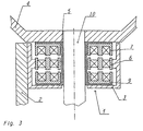
- the steering device comprises an inductive module 1, which has as essential components a rotatably connected to the vehicle 2 stator 3 and a rotatably connected to the steering wheel 4 rotor 5.
- the stator 3 and the rotor 5 in this case comprise annular Flußleit stresses arranged 6,7,8,9, which are arranged concentrically to the steering wheel axis of rotation, for example, consist of a filled with a soft magnetic material thermoplastic material.
- the rotary transformer is operated here with two by 90 ° to each other rotated primary coils, which are each formed by the electrical series connection of the opposing coils 6.1 and 6.3 and 6.2 and 6.4.
- the rotor side of the rotary transformer is similar to the stator but constructed with six coils 7.1, ..., 7.6, of which also two opposite are interconnected, whereby three by 60 ° against each other twisted secondary coils are formed.
- the evaluation of the voltage across one of the secondary coils is sufficient for the angle detection; in order to maximize the coupling between the primary and secondary side with regard to the energy transmission and to avoid coverage gaps for the angle detection, the other two secondary coils are also required. Due to the ohmic winding resistances and the leakage inductances of the rotary transformer, a load-dependent phase shift occurs between primary and secondary voltages. Therefore, between the secondary consumers with different power consumption and the secondary side of the transformer to provide a buffer that loads the transformer always with a constant load current to ensure trouble-free determination of the steering angle at any time.
- the Flußleit stresses 8 and 9 which are identically constructed and each carrying six coils of copper wire wound 8.1, ..., 8.6 and 9.1, ..., 9.6, which are arranged as seen in Fig.2b, cooperate with each other for the realization of a Rotary field motor for generating torque between the vehicle 2 and steering wheel 4, wherein the Flußleit stresses 8 with the stator 3 and the Flußleit Sciences 9 is rotatably connected to the rotor 5. Similar to the rotary transformer described above, the electric series connection of the opposing coils on the stator side - in this case 8.1 and 8.4, 8.2 and 8.5 and 8.3 and 8.6 - formed by 60 ° against each other twisted field magnets, which by appropriate control a generate magnetic rotating field.
- This rotating field can exert a torque on a magnetic armature, which, for example, in the simplest case can be a dipole formed by two opposing coils 9.1 and 9.4 on the rotor side, or else a more complex magnetic structure formed with the involvement of further rotor coils.
- a magnetic armature which, for example, in the simplest case can be a dipole formed by two opposing coils 9.1 and 9.4 on the rotor side, or else a more complex magnetic structure formed with the involvement of further rotor coils.
Landscapes
- Engineering & Computer Science (AREA)
- Mechanical Engineering (AREA)
- Chemical & Material Sciences (AREA)
- Combustion & Propulsion (AREA)
- Transportation (AREA)
- Power Steering Mechanism (AREA)
- Steering Controls (AREA)
- Transmission And Conversion Of Sensor Element Output (AREA)
- Steering Control In Accordance With Driving Conditions (AREA)
Claims (14)
- Dispositif de direction pour un véhicule automobile, avec un module inductif (1) qui, présentant un stator (3) associé solidaire en rotation avec ledit véhicule (2), et un rotor (5) associé solidaire en rotation avec le volant (4), comprenant un transducteur de rotation à base d'un résolveur pour le transfert sans contact d'énergie électrique et de données entre le véhicule automobile (2) et le volant (4), ainsi que pour la détection de l'angle de rotation du volant (4), et un moteur à champ rotatif annulaire pour la génération de couples de rotation entre le véhicule automobile (2) et le volant (4), le stator (3) et le rotor (5) comprennent des bobines (6.1,..., 9.y') qui coopèrent les unes avec les autres de manière à donner un couplage inductif entre les bobines (6.1,..., 6x, 8.1,..., 8.y), prévues, côté stator (3), pour la réalisation de la fonction de transducteur de rotation, et les bobines (7.1,..., 7.x', 9.1,..., 9.y') côté rotor (5), qui leur sont respectivement associées.
- Dispositif de direction selon la revendication 1, caractérisé en ce que, pour la réalisation de la fonction de transducteur de rotation et la fonction de moteur à champ rotatif, au moins trois bobines, disposée, à intervalles égaux, sur une circonférence autour de l'axe de rotation du volant (4) sont respectivement prévues côté stator (3) et côté rotor (5).
- Dispositif de direction selon la revendication 1, caractérisé en ce que les bobines (6.1,..., 9.y'), prévues pour la réalisation de la fonction de transducteur de rotation et de la fonction de moteur à champ rotatif sont disposées concentriquement les uns par rapport aux autres, dans un plan perpendiculaire à l'axe de rotation du volant.
- Dispositif de direction selon la revendication 1 ou 2, caractérisé en ce que les bobines (6.1,..., 9.y'), prévues pour la réalisation de la fonction de transducteur de rotation et la fonction de moteur à champ rotatif, sont disposées dans des plans perpendiculaires à l'axe de rotation du volant, décalés dans le sens axial les uns par rapport aux autres.
- Dispositif de direction selon l'une des revendications 1 à 4, caractérisé en ce que les axes des bobines (6.1,..., 9.y'), prévues pour la réalisation de la fonction de transducteur de rotation et de la fonction de moteur à champ rotatif sont orientés dans le sens radial par rapport à l'axe de rotation du volant.
- Dispositif de direction selon l'une des revendications 1 à 4, caractérisé en ce que les axes des bobines (6.1,..., 9.y'), prévues pour la réalisation de la fonction de transducteur de rotation et de la fonction du moteur à champ rotatif sont orientés parallèlement à l'axe de rotation du volant.
- Dispositif de direction selon l'une des revendications 1 à 4, caractérisé en ce que le nombre et / ou la disposition des bobines (6.1,...6.x, 8.1,..., 8.y) côté stator (3) ne sont pas les mêmes que le nombre et / ou la disposition des bobines (7.1,..., 7.x', 9.1,..., 9y') côté rotor (5) qui sont associées à celles-ci.
- Dispositif de direction selon l'une des revendications 1 à 7, caractérisé en ce que le stator (3) et le rotor (5) comprennent des corps conducteurs de flux (6, 7, 8, 9) conçus sensiblement en forme d'anneaux, qui, dans le secteur des bobines, présentent une coupe transversale radiale en forme de E et, dans le secteur situé entre les bobines, une coupe transversale radiale en forme de U.
- Dispositif de direction selon la revendication 8, caractérisé en ce que les corps conducteurs de flux (6, 7, 8, 9) consistent en une matière thermoplastique, chargée d'un matériau magnétique doux.
- Dispositif de direction selon la revendication 9, caractérisé en ce que les corps conducteurs de flux (6, 7, 8, 9) sont réalisés par enrobage thermoplastique des bobines avec une matière plastique chargée d'un matériau magnétique doux.
- Dispositif de direction selon l'une des revendications 1 à 10, caractérisé en ce que, du côté stator (3), les mêmes bobines (6.1,..., 6.x) sont prévues pour la réalisation de la fonction de transducteur de rotation et de la fonction de moteur à champ rotatif.
- Dispositif de direction selon l'une des revendications 1 à 10, caractérisé en ce que, du côté stator (3) et du côté rotor (5), les mêmes bobines (6.1,..., 6.x, 7.1,..., 7.x') sont prévues pour la réalisation de la fonction de transducteur de rotation et la fonction de moteur à champ rotatif, une excitation des bobines ou des groupes de bobines individuels décalée dans le temps étant prévue.
- Dispositif de direction selon l'une des revendications 1 à 10, caractérisé en ce que le volant (4) est relié, par un arbre de direction (10), directement à un mécanisme de direction qui influence la position des roues du véhicule par l'intermédiaire d'une timonerie de direction, les couples de rotation, générés par le moteur à champ rotatif étant mis à contribution pour renforcer les forces de braquage appliquées par le conducteur du véhicule.
- Dispositif de direction selon l'une des revendications 1 à 10, caractérisé en ce que la position angulaire du volant déterminée au moyen du transducteur de rotation pour influencer la position des roues du véhicules est mise à contribution par des auxiliaires électromoteurs, et que les couples, générés par le moteur à champ rotatif en tant que couples antagonistes au braquage, pour réaliser une réponse haptique destinée au conducteur du véhicule sont mis à contribution.
Applications Claiming Priority (2)
| Application Number | Priority Date | Filing Date | Title |
|---|---|---|---|
| DE19920092A DE19920092C2 (de) | 1999-05-03 | 1999-05-03 | Lenkeinrichtung für ein Kraftfahrzeug |
| DE19920092 | 1999-05-03 |
Publications (3)
| Publication Number | Publication Date |
|---|---|
| EP1050437A2 EP1050437A2 (fr) | 2000-11-08 |
| EP1050437A3 EP1050437A3 (fr) | 2003-08-27 |
| EP1050437B1 true EP1050437B1 (fr) | 2005-03-30 |
Family
ID=7906672
Family Applications (1)
| Application Number | Title | Priority Date | Filing Date |
|---|---|---|---|
| EP00108937A Expired - Lifetime EP1050437B1 (fr) | 1999-05-03 | 2000-04-27 | Direction pour un véhicule automobile |
Country Status (6)
| Country | Link |
|---|---|
| US (1) | US6343670B1 (fr) |
| EP (1) | EP1050437B1 (fr) |
| JP (1) | JP2001010516A (fr) |
| AT (1) | ATE292029T1 (fr) |
| DE (2) | DE19920092C2 (fr) |
| ES (1) | ES2238948T3 (fr) |
Families Citing this family (27)
| Publication number | Priority date | Publication date | Assignee | Title |
|---|---|---|---|---|
| WO1999001878A1 (fr) * | 1997-07-03 | 1999-01-14 | The Furukawa Electric Co., Ltd. | Transformateur dissocie et controleur d'emission equipe de ce transformateur dissocie |
| US6494705B1 (en) * | 2000-05-18 | 2002-12-17 | Stephen Feilinger | Apparatus for rotational mold with movable insert |
| DE10221242B4 (de) * | 2002-05-13 | 2012-10-25 | Leopold Kostal Gmbh & Co. Kg | Lenkeinrichtung für ein Kraftfahrzeug |
| US6873247B2 (en) * | 2002-10-25 | 2005-03-29 | Lear Corporation | Combined vehicle immobilizing and steering column control system |
| DE10258871A1 (de) * | 2002-12-17 | 2004-07-01 | Robert Bosch Gmbh | Steer-by-Wire-Lenkvorrichtung und Verfahren zum Lenken eines Fahrzeugs |
| US7405540B2 (en) * | 2003-10-20 | 2008-07-29 | Teleflex Megatech, Inc. | Secondary power supply system and method of activating subsystems from a vehicle steering wheel |
| US7525449B1 (en) | 2003-10-20 | 2009-04-28 | Teleflex Megatech, Inc. | Status light for switch on boat steering wheel |
| JP3915806B2 (ja) * | 2003-11-11 | 2007-05-16 | セイコーエプソン株式会社 | 電気光学装置および電子機器 |
| DE10353266B4 (de) * | 2003-11-14 | 2013-02-21 | Süd-Chemie Ip Gmbh & Co. Kg | Lithiumeisenphosphat, Verfahren zu seiner Herstellung und seine Verwendung als Elektrodenmaterial |
| US7672759B1 (en) | 2004-02-24 | 2010-03-02 | Teleflex Megatech, Inc. | Communication with a steering wheel switch |
| DE102004019066B3 (de) * | 2004-04-20 | 2005-12-08 | Autoliv Development Ab | Steer-by-Wire-Lenkradeinheit mit integriertem Airbagmodul |
| US7135981B1 (en) | 2004-10-12 | 2006-11-14 | Teleflex Megatech Inc. | Fuel level variation detector for marine vehicle |
| WO2009147574A1 (fr) * | 2008-06-02 | 2009-12-10 | Philips Intellectual Property & Standards Gmbh | Transformateur de puissance tournant destiné à être utilisé dans un circuit de génération de haute-tension afin de transmettre par induction au moins deux tensions d'alimentation pouvant être commandées de façon indépendante aux bornes d'alimentation d'une charge |
| JP5041447B2 (ja) * | 2010-03-30 | 2012-10-03 | 古河電気工業株式会社 | 回転コネクタ装置 |
| US8542085B2 (en) * | 2011-02-28 | 2013-09-24 | GM Global Technology Operations LLC | High frequency rotary transformer for synchronous electrical machines |
| US8742715B2 (en) | 2011-06-09 | 2014-06-03 | Simmonds Precision Products, Inc. | System and method for providing control of an electric motor using inductive rotary sensor |
| US9425654B2 (en) | 2013-09-30 | 2016-08-23 | Google Inc. | Contactless electrical coupling for a rotatable LIDAR device |
| US9823349B2 (en) * | 2014-04-16 | 2017-11-21 | Ford Global Technologies, Llc | Driver entry detector for a motor vehicle |
| DE102015217051A1 (de) * | 2015-09-07 | 2017-03-09 | Volkswagen Aktiengesellschaft | Nutzfahrzeuglenkung |
| EP3197029B1 (fr) | 2016-01-19 | 2019-05-29 | Gebrüder Klöcker GmbH | Dispositif a moteur electrique destine a former une lisiere de gaze, en particulier pour un metier a tisser, et metier a tisser a projectiles dote d'un tel dispositif |
| DE102017218676B4 (de) * | 2017-10-19 | 2023-03-23 | Robert Bosch Gmbh | LIDAR-Sensor mit einer Vorrichtung zur kontaktlosen Übertragung von Daten und von Energie und zur Winkelmessung |
| EP3552886A1 (fr) * | 2018-04-09 | 2019-10-16 | IDT Europe GmbH | Interface de capteur sans fil pour volant de direction |
| DE102019118479A1 (de) * | 2019-07-09 | 2021-01-14 | Schaeffler Technologies AG & Co. KG | Feedback-Aktuator für eine Lenkeinrichtung eines Fahrzeugs |
| DE102020212268A1 (de) * | 2020-09-29 | 2022-03-31 | Universität Stuttgart | Vereinigung von Resolver und induktiver Rotorversorgung in einem magnetischen Kreis |
| CN113602344B (zh) * | 2021-08-13 | 2022-06-07 | 吉林大学 | 一种位置旋变外置式车轮转向机构 |
| DE102023135072B4 (de) * | 2023-12-14 | 2025-11-27 | Schaeffler Technologies AG & Co. KG | Lenkeinheit für eine Steer-by-wire-Lenkung und Verfahren zur Herstellung eines Feedback-Aktuators |
| DE102023212786A1 (de) * | 2023-12-15 | 2025-06-18 | Joyson Safety Systems Germany Gmbh | Vorrichtung für ein Lenkrad eines Fahrzeugs |
Family Cites Families (9)
| Publication number | Priority date | Publication date | Assignee | Title |
|---|---|---|---|---|
| JPS58142509A (ja) * | 1982-02-19 | 1983-08-24 | Hitachi Ltd | 回転部分を有する自動車部品への電源供給装置 |
| DE4009400A1 (de) * | 1990-03-23 | 1991-09-26 | Porsche Ag | Aktuator fuer eine kybernetische lenkung |
| US5394760A (en) * | 1992-06-03 | 1995-03-07 | Trw Inc. | Torque sensor for a power assist steering system |
| GB9225971D0 (en) * | 1992-12-12 | 1993-02-10 | Penny & Giles Blackwood Ltd | Rotary transducer |
| JP3516315B2 (ja) * | 1995-07-05 | 2004-04-05 | 本田技研工業株式会社 | 電動パワーステアリング装置 |
| KR100458378B1 (ko) * | 1996-05-17 | 2005-04-06 | 혼다 기켄 고교 가부시키가이샤 | 전동파워스티어링장치 |
| US5979587A (en) * | 1997-06-06 | 1999-11-09 | Ford Global Technologies, Inc. | Electrically assisted power steering apparatus |
| DE19736346C1 (de) * | 1997-08-21 | 1999-01-28 | Kostal Leopold Gmbh & Co Kg | Vorrichtung zur Übertragung von elektrischer Energie zwischen der Fahrzeugseite und der Lenkradseite eines Kraftfahrzeuges |
| KR100308385B1 (ko) * | 1999-02-10 | 2001-09-26 | 밍 루 | 차량용 동력 조향장치의 반력장치 |
-
1999
- 1999-05-03 DE DE19920092A patent/DE19920092C2/de not_active Expired - Fee Related
-
2000
- 2000-04-27 AT AT00108937T patent/ATE292029T1/de not_active IP Right Cessation
- 2000-04-27 DE DE50009894T patent/DE50009894D1/de not_active Expired - Lifetime
- 2000-04-27 EP EP00108937A patent/EP1050437B1/fr not_active Expired - Lifetime
- 2000-04-27 ES ES00108937T patent/ES2238948T3/es not_active Expired - Lifetime
- 2000-05-01 JP JP2000132659A patent/JP2001010516A/ja not_active Withdrawn
- 2000-05-02 US US09/562,714 patent/US6343670B1/en not_active Expired - Fee Related
Also Published As
| Publication number | Publication date |
|---|---|
| EP1050437A2 (fr) | 2000-11-08 |
| JP2001010516A (ja) | 2001-01-16 |
| US6343670B1 (en) | 2002-02-05 |
| DE19920092A1 (de) | 2000-11-16 |
| EP1050437A3 (fr) | 2003-08-27 |
| DE50009894D1 (de) | 2005-05-04 |
| ES2238948T3 (es) | 2005-09-16 |
| ATE292029T1 (de) | 2005-04-15 |
| DE19920092C2 (de) | 2002-11-14 |
Similar Documents
| Publication | Publication Date | Title |
|---|---|---|
| EP1050437B1 (fr) | Direction pour un véhicule automobile | |
| DE69526770T2 (de) | Resolver für Reluktanzmotor für Lenkhilfe mit Ringen und sinusförmigen Leitern | |
| DE69523406T2 (de) | Elektrisches Hilfskraftlenksystem und Verfahren zum Steuern eines solchen Systems | |
| DE60032271T2 (de) | Verbesserungen in Verbindung mit elektrischen Servolenksystemen | |
| EP2160816B1 (fr) | Moteur synchrone à 12 dents statoriques et 10 pôles rotoriques | |
| DE2811282C2 (de) | Trägheitsschwungrad | |
| DE60024383T2 (de) | Motor/Generator mit mehreren Läufern | |
| DE60218935T2 (de) | Drehende elektrische Maschine mit Drehstromringspulen und Dauermagneten | |
| DE3617772C2 (fr) | ||
| EP2047586B1 (fr) | Moteur synchrone, système de moteur et procédé pour commander un système de moteur | |
| DE2802753C2 (de) | Synchronmaschine | |
| DE102013009776A1 (de) | Motorantriebssystem | |
| EP0451551A1 (fr) | Système d'entraînement électrique pour véhicule | |
| EP3232547A1 (fr) | Procédé de fonctionnement d'une machine électrique et machine electrique | |
| DE3626597A1 (de) | Elektrisches leistungssteuersystem fuer kraftfahrzeuge | |
| DE69402797T2 (de) | Linearer Schrittmotor | |
| EP0721248A2 (fr) | Entraînement électrique avec plus qu'un rotor excité par un aimant permanent | |
| DE1908579A1 (de) | Buersten- und lagerloser Drehfeldgeber | |
| DE19806611A1 (de) | Elektromechanische Bedieneinrichtung | |
| DE19722453C1 (de) | Elektrisches Antriebssystem | |
| WO2019001827A1 (fr) | Train d'entraînement avionique ou automoteur comprenant une machine électrique | |
| DE102021100728B3 (de) | Antriebseinheit für ein Kraftfahrzeug | |
| DE102018203566B4 (de) | Elektromechanischer Energiewandler mit einem inneren und einem äußeren Energiewandler | |
| DE102011078994A1 (de) | Elektrische Maschine für einen Lenkantrieb | |
| DE4218888C2 (de) | Elektrische Maschine |
Legal Events
| Date | Code | Title | Description |
|---|---|---|---|
| PUAI | Public reference made under article 153(3) epc to a published international application that has entered the european phase |
Free format text: ORIGINAL CODE: 0009012 |
|
| AK | Designated contracting states |
Kind code of ref document: A2 Designated state(s): AT BE CH CY DE DK ES FI FR GB GR IE IT LI LU MC NL PT SE |
|
| AX | Request for extension of the european patent |
Free format text: AL;LT;LV;MK;RO;SI |
|
| PUAL | Search report despatched |
Free format text: ORIGINAL CODE: 0009013 |
|
| AK | Designated contracting states |
Designated state(s): AT BE CH CY DE DK ES FI FR GB GR IE IT LI LU MC NL PT SE |
|
| AX | Request for extension of the european patent |
Extension state: AL LT LV MK RO SI |
|
| 17P | Request for examination filed |
Effective date: 20040227 |
|
| AKX | Designation fees paid |
Designated state(s): AT BE CH CY DE DK ES FI FR GB GR IE IT LI LU MC NL PT SE |
|
| GRAP | Despatch of communication of intention to grant a patent |
Free format text: ORIGINAL CODE: EPIDOSNIGR1 |
|
| GRAS | Grant fee paid |
Free format text: ORIGINAL CODE: EPIDOSNIGR3 |
|
| GRAA | (expected) grant |
Free format text: ORIGINAL CODE: 0009210 |
|
| AK | Designated contracting states |
Kind code of ref document: B1 Designated state(s): AT BE CH CY DE DK ES FI FR GB GR IE IT LI LU MC NL PT SE |
|
| PG25 | Lapsed in a contracting state [announced via postgrant information from national office to epo] |
Ref country code: NL Free format text: LAPSE BECAUSE OF FAILURE TO SUBMIT A TRANSLATION OF THE DESCRIPTION OR TO PAY THE FEE WITHIN THE PRESCRIBED TIME-LIMIT Effective date: 20050330 Ref country code: FI Free format text: LAPSE BECAUSE OF FAILURE TO SUBMIT A TRANSLATION OF THE DESCRIPTION OR TO PAY THE FEE WITHIN THE PRESCRIBED TIME-LIMIT Effective date: 20050330 Ref country code: IE Free format text: LAPSE BECAUSE OF FAILURE TO SUBMIT A TRANSLATION OF THE DESCRIPTION OR TO PAY THE FEE WITHIN THE PRESCRIBED TIME-LIMIT Effective date: 20050330 |
|
| REG | Reference to a national code |
Ref country code: GB Ref legal event code: FG4D Free format text: NOT ENGLISH |
|
| REG | Reference to a national code |
Ref country code: CH Ref legal event code: EP |
|
| PG25 | Lapsed in a contracting state [announced via postgrant information from national office to epo] |
Ref country code: LU Free format text: LAPSE BECAUSE OF NON-PAYMENT OF DUE FEES Effective date: 20050427 Ref country code: AT Free format text: LAPSE BECAUSE OF NON-PAYMENT OF DUE FEES Effective date: 20050427 Ref country code: CY Free format text: LAPSE BECAUSE OF FAILURE TO SUBMIT A TRANSLATION OF THE DESCRIPTION OR TO PAY THE FEE WITHIN THE PRESCRIBED TIME-LIMIT Effective date: 20050427 |
|
| PG25 | Lapsed in a contracting state [announced via postgrant information from national office to epo] |
Ref country code: MC Free format text: LAPSE BECAUSE OF NON-PAYMENT OF DUE FEES Effective date: 20050430 Ref country code: LI Free format text: LAPSE BECAUSE OF NON-PAYMENT OF DUE FEES Effective date: 20050430 Ref country code: CH Free format text: LAPSE BECAUSE OF NON-PAYMENT OF DUE FEES Effective date: 20050430 Ref country code: BE Free format text: LAPSE BECAUSE OF NON-PAYMENT OF DUE FEES Effective date: 20050430 |
|
| REF | Corresponds to: |
Ref document number: 50009894 Country of ref document: DE Date of ref document: 20050504 Kind code of ref document: P |
|
| REG | Reference to a national code |
Ref country code: IE Ref legal event code: FG4D Free format text: LANGUAGE OF EP DOCUMENT: GERMAN |
|
| GBT | Gb: translation of ep patent filed (gb section 77(6)(a)/1977) |
Effective date: 20050517 |
|
| PG25 | Lapsed in a contracting state [announced via postgrant information from national office to epo] |
Ref country code: GR Free format text: LAPSE BECAUSE OF FAILURE TO SUBMIT A TRANSLATION OF THE DESCRIPTION OR TO PAY THE FEE WITHIN THE PRESCRIBED TIME-LIMIT Effective date: 20050630 Ref country code: DK Free format text: LAPSE BECAUSE OF FAILURE TO SUBMIT A TRANSLATION OF THE DESCRIPTION OR TO PAY THE FEE WITHIN THE PRESCRIBED TIME-LIMIT Effective date: 20050630 |
|
| PG25 | Lapsed in a contracting state [announced via postgrant information from national office to epo] |
Ref country code: PT Free format text: LAPSE BECAUSE OF FAILURE TO SUBMIT A TRANSLATION OF THE DESCRIPTION OR TO PAY THE FEE WITHIN THE PRESCRIBED TIME-LIMIT Effective date: 20050907 |
|
| REG | Reference to a national code |
Ref country code: ES Ref legal event code: FG2A Ref document number: 2238948 Country of ref document: ES Kind code of ref document: T3 |
|
| NLV1 | Nl: lapsed or annulled due to failure to fulfill the requirements of art. 29p and 29m of the patents act | ||
| BERE | Be: lapsed |
Owner name: LEOPOLD KOSTAL G.M.B.H. & CO. KG Effective date: 20050430 |
|
| REG | Reference to a national code |
Ref country code: IE Ref legal event code: FD4D |
|
| REG | Reference to a national code |
Ref country code: CH Ref legal event code: PL |
|
| PLBE | No opposition filed within time limit |
Free format text: ORIGINAL CODE: 0009261 |
|
| STAA | Information on the status of an ep patent application or granted ep patent |
Free format text: STATUS: NO OPPOSITION FILED WITHIN TIME LIMIT |
|
| 26N | No opposition filed |
Effective date: 20060102 |
|
| PGFP | Annual fee paid to national office [announced via postgrant information from national office to epo] |
Ref country code: IT Payment date: 20060430 Year of fee payment: 7 |
|
| EN | Fr: translation not filed | ||
| ET | Fr: translation filed | ||
| REG | Reference to a national code |
Ref country code: FR Ref legal event code: EERR Free format text: CORRECTION DE BOPI 06/21 - BREVETS EUROPEENS DONT LA TRADUCTION N A PAS ETE REMISE A L INPI. IL Y A LIEU DE SUPPRIMER : LA MENTION DE LA NON REMISE. LA REMISE DE LA TRADUCTION EST PUBLIEE DANS LE PRESENT BOPI. |
|
| BERE | Be: lapsed |
Owner name: LEOPOLD KOSTAL G.M.B.H. & CO. KG Effective date: 20050430 |
|
| PG25 | Lapsed in a contracting state [announced via postgrant information from national office to epo] |
Ref country code: SE Free format text: LAPSE BECAUSE OF FAILURE TO SUBMIT A TRANSLATION OF THE DESCRIPTION OR TO PAY THE FEE WITHIN THE PRESCRIBED TIME-LIMIT Effective date: 20050630 |
|
| PGFP | Annual fee paid to national office [announced via postgrant information from national office to epo] |
Ref country code: ES Payment date: 20090429 Year of fee payment: 10 |
|
| PGFP | Annual fee paid to national office [announced via postgrant information from national office to epo] |
Ref country code: FR Payment date: 20090427 Year of fee payment: 10 |
|
| PG25 | Lapsed in a contracting state [announced via postgrant information from national office to epo] |
Ref country code: IT Free format text: LAPSE BECAUSE OF NON-PAYMENT OF DUE FEES Effective date: 20070427 |
|
| PGFP | Annual fee paid to national office [announced via postgrant information from national office to epo] |
Ref country code: GB Payment date: 20090430 Year of fee payment: 10 |
|
| GBPC | Gb: european patent ceased through non-payment of renewal fee |
Effective date: 20100427 |
|
| REG | Reference to a national code |
Ref country code: FR Ref legal event code: ST Effective date: 20101230 |
|
| PG25 | Lapsed in a contracting state [announced via postgrant information from national office to epo] |
Ref country code: GB Free format text: LAPSE BECAUSE OF NON-PAYMENT OF DUE FEES Effective date: 20100427 |
|
| REG | Reference to a national code |
Ref country code: ES Ref legal event code: FD2A Effective date: 20110714 |
|
| PG25 | Lapsed in a contracting state [announced via postgrant information from national office to epo] |
Ref country code: ES Free format text: LAPSE BECAUSE OF NON-PAYMENT OF DUE FEES Effective date: 20110704 |
|
| PG25 | Lapsed in a contracting state [announced via postgrant information from national office to epo] |
Ref country code: ES Free format text: LAPSE BECAUSE OF NON-PAYMENT OF DUE FEES Effective date: 20100428 |
|
| PG25 | Lapsed in a contracting state [announced via postgrant information from national office to epo] |
Ref country code: FR Free format text: LAPSE BECAUSE OF NON-PAYMENT OF DUE FEES Effective date: 20100430 |
|
| PGFP | Annual fee paid to national office [announced via postgrant information from national office to epo] |
Ref country code: DE Payment date: 20130330 Year of fee payment: 14 |
|
| REG | Reference to a national code |
Ref country code: DE Ref legal event code: R119 Ref document number: 50009894 Country of ref document: DE |
|
| REG | Reference to a national code |
Ref country code: DE Ref legal event code: R119 Ref document number: 50009894 Country of ref document: DE Effective date: 20141101 |
|
| PG25 | Lapsed in a contracting state [announced via postgrant information from national office to epo] |
Ref country code: DE Free format text: LAPSE BECAUSE OF NON-PAYMENT OF DUE FEES Effective date: 20141101 |