EP1050471A2 - Transporteur pour boítes pliantes dans une machine d'emballage - Google Patents
Transporteur pour boítes pliantes dans une machine d'emballage Download PDFInfo
- Publication number
- EP1050471A2 EP1050471A2 EP00107829A EP00107829A EP1050471A2 EP 1050471 A2 EP1050471 A2 EP 1050471A2 EP 00107829 A EP00107829 A EP 00107829A EP 00107829 A EP00107829 A EP 00107829A EP 1050471 A2 EP1050471 A2 EP 1050471A2
- Authority
- EP
- European Patent Office
- Prior art keywords
- section
- packaging machine
- plunger
- conveyor
- machine according
- Prior art date
- Legal status (The legal status is an assumption and is not a legal conclusion. Google has not performed a legal analysis and makes no representation as to the accuracy of the status listed.)
- Withdrawn
Links
Images
Classifications
-
- B—PERFORMING OPERATIONS; TRANSPORTING
- B65—CONVEYING; PACKING; STORING; HANDLING THIN OR FILAMENTARY MATERIAL
- B65B—MACHINES, APPARATUS OR DEVICES FOR, OR METHODS OF, PACKAGING ARTICLES OR MATERIALS; UNPACKING
- B65B7/00—Closing containers or receptacles after filling
- B65B7/16—Closing semi-rigid or rigid containers or receptacles not deformed by, or not taking-up shape of, contents, e.g. boxes or cartons
- B65B7/20—Closing semi-rigid or rigid containers or receptacles not deformed by, or not taking-up shape of, contents, e.g. boxes or cartons by folding-down preformed flaps
-
- B—PERFORMING OPERATIONS; TRANSPORTING
- B65—CONVEYING; PACKING; STORING; HANDLING THIN OR FILAMENTARY MATERIAL
- B65B—MACHINES, APPARATUS OR DEVICES FOR, OR METHODS OF, PACKAGING ARTICLES OR MATERIALS; UNPACKING
- B65B43/00—Forming, feeding, opening or setting-up containers or receptacles in association with packaging
- B65B43/38—Opening hinged lids
- B65B43/39—Opening-out closure flaps clear of bag, box, or carton mouth
-
- B—PERFORMING OPERATIONS; TRANSPORTING
- B65—CONVEYING; PACKING; STORING; HANDLING THIN OR FILAMENTARY MATERIAL
- B65B—MACHINES, APPARATUS OR DEVICES FOR, OR METHODS OF, PACKAGING ARTICLES OR MATERIALS; UNPACKING
- B65B43/00—Forming, feeding, opening or setting-up containers or receptacles in association with packaging
- B65B43/42—Feeding or positioning bags, boxes, or cartons in the distended, opened, or set-up state; Feeding preformed rigid containers, e.g. tins, capsules, glass tubes, glasses, to the packaging position; Locating containers or receptacles at the filling position; Supporting containers or receptacles during the filling operation
- B65B43/48—Feeding or positioning bags, boxes, or cartons in the distended, opened, or set-up state; Feeding preformed rigid containers, e.g. tins, capsules, glass tubes, glasses, to the packaging position; Locating containers or receptacles at the filling position; Supporting containers or receptacles during the filling operation using reciprocating or oscillating pushers
-
- B—PERFORMING OPERATIONS; TRANSPORTING
- B65—CONVEYING; PACKING; STORING; HANDLING THIN OR FILAMENTARY MATERIAL
- B65B—MACHINES, APPARATUS OR DEVICES FOR, OR METHODS OF, PACKAGING ARTICLES OR MATERIALS; UNPACKING
- B65B43/00—Forming, feeding, opening or setting-up containers or receptacles in association with packaging
- B65B43/42—Feeding or positioning bags, boxes, or cartons in the distended, opened, or set-up state; Feeding preformed rigid containers, e.g. tins, capsules, glass tubes, glasses, to the packaging position; Locating containers or receptacles at the filling position; Supporting containers or receptacles during the filling operation
- B65B43/52—Feeding or positioning bags, boxes, or cartons in the distended, opened, or set-up state; Feeding preformed rigid containers, e.g. tins, capsules, glass tubes, glasses, to the packaging position; Locating containers or receptacles at the filling position; Supporting containers or receptacles during the filling operation using roller-ways or endless conveyors
-
- B—PERFORMING OPERATIONS; TRANSPORTING
- B65—CONVEYING; PACKING; STORING; HANDLING THIN OR FILAMENTARY MATERIAL
- B65B—MACHINES, APPARATUS OR DEVICES FOR, OR METHODS OF, PACKAGING ARTICLES OR MATERIALS; UNPACKING
- B65B49/00—Devices for folding or bending wrappers around contents
- B65B49/08—Reciprocating or oscillating folders
-
- B—PERFORMING OPERATIONS; TRANSPORTING
- B65—CONVEYING; PACKING; STORING; HANDLING THIN OR FILAMENTARY MATERIAL
- B65B—MACHINES, APPARATUS OR DEVICES FOR, OR METHODS OF, PACKAGING ARTICLES OR MATERIALS; UNPACKING
- B65B49/00—Devices for folding or bending wrappers around contents
- B65B49/14—Folders forming part of, or attached to, conveyors for partially-wrapped articles
-
- F—MECHANICAL ENGINEERING; LIGHTING; HEATING; WEAPONS; BLASTING
- F16—ENGINEERING ELEMENTS AND UNITS; GENERAL MEASURES FOR PRODUCING AND MAINTAINING EFFECTIVE FUNCTIONING OF MACHINES OR INSTALLATIONS; THERMAL INSULATION IN GENERAL
- F16H—GEARING
- F16H25/00—Gearings comprising primarily only cams, cam-followers and screw-and-nut mechanisms
- F16H25/16—Gearings comprising primarily only cams, cam-followers and screw-and-nut mechanisms for interconverting rotary motion and oscillating motion
Definitions
- the invention relates to a packaging machine a packaging conveyor, in particular a folding box conveyor, and with a transverse thruster, the one essentially perpendicular to the conveying direction of the Packaging conveyor has movable plunger, by means of which one arranged on the packaging conveyor Packaging can be moved perpendicular to the conveying direction is, the plunger on a substantially parallel to the conveying direction of the packaging conveyor with the same Speed like this endlessly rotating transport device is slidably mounted and one being the Movement of the ram determining cam provided which is a first section for the axial extension movement of the plunger and an adjoining one second section for the axial feed movement of the Has tappet.
- an endless revolving packaging conveyor for example a so-called folding box chain
- an endless rotating conveyor for the products for example, a so-called product chain
- the folding box chain and the product chain are so synchronized in their movements that the product transverse to the direction of movement of the chains in the folding box can be inserted.
- the plunger After a folding box across using the pestle has been moved, the plunger returns to its retracted position Starting position back, from which he then shifted sideways the next folding box again becomes. This plunger reciprocation is needed relatively much time and limits the clock frequency and thus the performance of the packaging machine essential.
- the plunger does not only carry one Extending or Extending movement and a correspondingly opposite Retraction movement, but the plunger is with the Sectional transport device parallel to the Packaging conveyor moved in the conveying direction, whereby the transport device and the packaging conveyor are preferably moved at the same speed, so that none between the plunger and the packaging Relative displacement in the direction of conveyance occurs as long as the plunger with the transport device parallel to the Packaging conveyor is moved.
- moving in The tappet picks up the control curve in the direction of conveyance the axial displacement, i.e. the extension movement and the Retraction movement of the ram determined.
- the endlessly rotating transport device At the end of the endlessly rotating transport device returns the plunger in the opposite direction to the conveying direction of the Packaging conveyor back to the starting position and can thus a cross-shift of another packaging initiate the packaging conveyor.
- the transport device Zab belt or a chain the one or the outside carries a guide part for the plunger, in which this is axially displaceable.
- the configuration of the transport device as parallel to the conveyor belt running endless belt or Belt makes it possible to on this or the transport device several guide parts for one plunger each to be attached at the same mutual distance, whereby the performance of the packaging machine is increased.
- the axial adjustment or displacement of the ram defining control curve has a first section for the axial extension movement of the ram and one on it subsequent second section for the axial feed movement of the plunger, each by a section the guide rail are formed.
- the axial extension movement of the ram to a changed format of the moving folding carton, the entire guide rail can be removed and replaced. In this way, the format changeover is time-consuming and expensive.
- the invention has for its object a transverse thrust device in a packaging machine of the named Kind of creating an easy and quick customization to the format of the folding box to be moved.
- This task is performed on a packaging machine mentioned type in that at least the first Section of the control curve from an adjustable contact surface is formed, on which a first role takes place. On in this way it is possible to change the starting position of the Tappet and / or its axial extension movement accordingly the format of the folding boxes to be moved adapt.
- a simple adjustment of the first section of the Control curve can be achieved if the adjustable Contact surface of an elastically deformable spring steel sheet is formed.
- the second section of the control curve which is the axial Determines the retraction movement of the ram, as a rule no adjustment to the respective folding box size, so that it is preferably provided that this second section from a fixed leadership especially in Form a guide groove is formed in the first Role expires.
- the Spring steel sheet in the transition area between the first Section and the second section of the control curve is held so that the surface of the spring steel sheet always merges smoothly into a wall of the guide groove, even if the spring steel sheet is adjusted, being off the adjustment of the spring steel sheet resulting axial Know movements are recorded.
- the adjustment of the Spring steel sheet is achieved in particular in that the opposite of the held end Starting area of the first section of the control curve a holder adjustable in the axial direction of the ram is stored.
- the extension movement and the retraction movement of the ram is preferably over the first and second sections the control curve executed when the plunger is in Area of the upper run of the endlessly rotating transport device located. Located at the end of the feed movement the ram at the end of the upper run of the transport device, is redirected and runs with further movement over the lower run back to the beginning of the upper run. During this return movement in the area of the The tappet is in a third section of the lower strand Control curve controlled during the guidance of the plunger the return of the rotating transport device takes over. Preferably this third section also formed on the spring steel sheet, so that in Transition from lower run to upper run a continuous Given contact surface on the uniform spring steel sheet is.
- the control curve To also between the the second section of the Control curve forming guide groove and the adjoining, formed by the spring steel sheet third section the control curve a secure mounting of the spring steel sheet To achieve this is in the above Transitional area held or clamped during the third section in its opposite end region is mounted on the holder. It is preferred provided that the third section of the control curve smoothly merges into the first section.
- the first role is the Control curve in its first and third section on the one side of the spring steel sheet and a second roller on the opposite side of the spring steel sheet taps.
- the axial displacement or position of the plunger reliably defined.
- second section of the control curve i.e. in the guide groove if only the first role intervenes, which makes the axial adjustment movement of the ram precise is defined.
- the transport device is a toothed belt, the outside of a guide part for the plunger, and several plungers in has the same mutual distance.
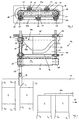
- FIG. 1 One shown in sections in Figures 1 and 2 Packaging machine has one in the conventional way Folding box conveyor 11, the in conveyor F is driven and a variety on its top of folding boxes S with their open sides, which each have side locking tabs S1, S2 or S3, S4 are assigned, aligned transversely to the conveying direction F. are.
- each folding box S is according to the Figure 1 lower side of a product, not shown introduced, whereby it must first be ensured that the lateral ones on the product introduction side Locking tabs S3 and S4 to release the insertion opening spread to the side or softened away become.
- transverse thrust device 12 reached that on the opposite side of the product introduction Side of the carton conveyor 11 is arranged and with the folding boxes one after the other across Conveying direction F are shifted, causing the lateral Locking tabs F3 and F4 by not contacting shown attacks deflected laterally outwards become.
- the transverse thrust device 12 comprises an endlessly rotating one Transport device in the form of a spaced two Deflection rollers 18, 19 guided toothed belt 17, which is parallel runs to the folding box conveyor 11.
- the one Deflection roller 18 is connected to a drive shaft 21, the in spaced bearing plates 15, 16 via bearings 22, 23 is rotatably mounted and in a manner not shown is driven.
- the toothed belt 17 is in the U direction driven in such a way that the upper run synchronously with the folding box conveyor 11 is moved in the conveying direction F, while the lower run runs in the opposite direction.
- the holder 20 run with around the toothed belt 17 and each support a tappet 13 such that this axially, i.e. perpendicular to the running direction U of the toothed belt 17 and thus perpendicular to the conveying direction F of the folding box conveyor 11 is displaceable.
- the plunger 13 carries on its front, the folding box conveyor 11 facing end a cushion 14 with which he comes into contact with the folding boxes S.
- each plunger 13 At the rear end of each plunger 13 are a first role 27 and a second roller 28 rotatably mounted in roll on a cam as described later and thereby the axial extension movement of the plunger 13 in Direction of the folding boxes S and its axial feed movement Taxes.
- the control curve comprises a first one Section for the axial extension movement of the plunger 13, a subsequent second section for the axial retraction movement of the ram and a third Section for guiding the ram during the return of the associated holder 20 in the area of the lower run of a timing belt 17.
- the second section of The control cam is formed by a plate 29 Guide groove 24 is formed, in which the first roller 27th is movable under a tight fit.
- the guide groove 24 runs from a position close to the toothed belt 17 its front end to one of the timing belt 17 distant position at its rear end, causing the first roller 27 when passing through the guide groove 24 of the toothed belt 17 moved away and the plunger 13 retracted becomes.
- the first section and the third section of the control curve are of a substantially U-shaped spring steel sheet 25 formed, the two U-legs have different lengths.
- the front end of the shorter U-leg 25 is fixed in the plate 29 held that a smooth, smooth transition between the surfaces of the U-leg 25a and the wall of the Guide groove 24 is formed.
- the U-leg 25a runs thereby from a position reset by the carrying belt 17 obliquely up to the transition into the guide groove 24, so that the first roller 27 facing the plunger 13 Bears against the U-leg 25a, and the second roller 28 on the opposite side of the U-leg 25a rests in the direction of the carrying belt 17th to be moved if it covers the first section of the Control curve forming U-leg 25a of the spring steel sheet 25 roll along, whereby the plunger 13 in the direction of Folding boxes S of the folding box conveyor 11 are extended becomes.
- the free end of the longer U-leg 25b of the spring steel sheet 25 is in the area of the end of the guide groove 24 held tight.
- the two U-legs 25a and 25b connecting deflection or base section of the spring steel sheets 25 is mounted on a holder 26 which is in the direction of movement the plunger 13 is adjustable, which too an adjustment of the control curve while deforming the Spring steel sheet 25 leads.
- the toothed belt 17 and the Folding box conveyors 11 are essentially the same Speed driven in the same direction.
- the folding box S is so far on the folding box conveyor according to Figure 1 11 moved down that the cross-thruster facing side locking tabs S1 and S2 Dip under a guide bar 11a and thereby in known manner held in its closed position become.
- the guide bar 11a also serves as a support when inserting the product, not shown the opposite side of the box 1.
- the holder 20 is then with the toothed belt 17th around the guide roller 18 down into the area of Deflected lower run and runs against this on the Direction of conveyance F back, the plunger 13 in this Movement along the lower run of the toothed belt 17 with its first roller 27 on the front surface and with its second roller 28 on the back surface of the longer U-leg 25b of the spring steel sheet 25 is in plant and therefore an undesirable Axial displacement is prevented.
Landscapes
- Engineering & Computer Science (AREA)
- Mechanical Engineering (AREA)
- General Engineering & Computer Science (AREA)
- Microelectronics & Electronic Packaging (AREA)
- Auxiliary Devices For And Details Of Packaging Control (AREA)
- Supplying Of Containers To The Packaging Station (AREA)
Applications Claiming Priority (2)
| Application Number | Priority Date | Filing Date | Title |
|---|---|---|---|
| DE19920614 | 1999-05-05 | ||
| DE19920614A DE19920614A1 (de) | 1999-05-05 | 1999-05-05 | Verpackungsmaschine |
Publications (1)
| Publication Number | Publication Date |
|---|---|
| EP1050471A2 true EP1050471A2 (fr) | 2000-11-08 |
Family
ID=7907021
Family Applications (1)
| Application Number | Title | Priority Date | Filing Date |
|---|---|---|---|
| EP00107829A Withdrawn EP1050471A2 (fr) | 1999-05-05 | 2000-04-12 | Transporteur pour boítes pliantes dans une machine d'emballage |
Country Status (4)
| Country | Link |
|---|---|
| US (1) | US6385945B1 (fr) |
| EP (1) | EP1050471A2 (fr) |
| JP (1) | JP2000344213A (fr) |
| DE (1) | DE19920614A1 (fr) |
Cited By (2)
| Publication number | Priority date | Publication date | Assignee | Title |
|---|---|---|---|---|
| EP2287076A1 (fr) * | 2010-05-21 | 2011-02-23 | CAMA 1 SpA | Machine pour la mise en carton de produits |
| IT202000031844A1 (it) * | 2020-12-22 | 2022-06-22 | Azionaria Costruzioni Macch Automatiche | Dispositivo di trattamento di contenitori per linea manifatturiera di confezionamento, linea manifatturiera di confezionamento di contenitori comprendente tale dispositivo di trattamento e metodo per trattare contenitori in una linea manifatturiera di confezionamento |
Families Citing this family (7)
| Publication number | Priority date | Publication date | Assignee | Title |
|---|---|---|---|---|
| IT1310270B1 (it) * | 1999-07-20 | 2002-02-11 | Ima Spa | Dispositivo per la piegatura delle falde di contenitori scatolari. |
| DE102005016123A1 (de) * | 2005-04-08 | 2006-10-12 | Robert Bosch Gmbh | Verpackungsmaschine zum Einschieben von Packgut in Packmittel |
| US20110016828A1 (en) * | 2009-07-23 | 2011-01-27 | Parker Richard A | Method And Apparatus For Labeling A Cap And Threading The Cap Onto A Bottle |
| CN103318478B (zh) * | 2013-06-14 | 2015-04-29 | 江西创一精密机械有限公司 | 装盒机的上压条自动翻起机构 |
| KR102233333B1 (ko) * | 2016-09-28 | 2021-03-29 | 봅스트 맥스 에스에이 | 판지 박스들과 같이 패키징 컨테이너들에 대해 충전하기 전에 플랩을 이격시키기 위한 디바이스 및 구비된 충전 스테이션들 |
| IT201700067729A1 (it) * | 2017-06-19 | 2017-09-19 | Mas Pack S R L | Sistema automatico per l’orientamento delle falde di scatole. |
| CN113844719B (zh) * | 2021-09-15 | 2022-06-03 | 广东金冠科技股份有限公司 | 一种智能全自动包装设备 |
Family Cites Families (12)
| Publication number | Priority date | Publication date | Assignee | Title |
|---|---|---|---|---|
| DE1139430B (de) * | 1959-08-21 | 1962-11-08 | Hesser Ag Maschf | Kartoniermaschine, insbesondere fuer Buendel stangenfoermiger Gegenstaende, z. B. Makkaroni |
| US3333396A (en) * | 1963-10-03 | 1967-08-01 | Fr Hesser Maschinenfabrik A G | Machine for filling cartons |
| AU440560B2 (en) * | 1968-04-30 | 1973-09-18 | Apparatus for packaging fish and various other products | |
| DE2032184A1 (de) * | 1969-07-15 | 1971-02-18 | Haum Werke, Korber & Co KG, 2050 Hamburg | Vorrichtung zum Herstellen und Füllen von Weichpackungen |
| AT311894B (de) * | 1970-08-03 | 1973-12-10 | Richter Gedeon Vegyeszet | Kartonauffaltvorrichtung für Verpackungsmaschinen |
| US3821874A (en) * | 1972-10-10 | 1974-07-02 | Jones & Co Inc R A | Cartoning machine for cartons having liners |
| US3879920A (en) * | 1974-01-17 | 1975-04-29 | Langen H J & Sons Ltd | Machine for forming wrap-around shipper packages |
| SE382964B (sv) * | 1974-11-18 | 1976-02-23 | Rigello Pak Ab | Anordning vid en forslutningsmaskin |
| US4159610A (en) * | 1978-01-27 | 1979-07-03 | H. J. Langen & Sons Ltd. | Closure mechanism for closing end of loaded cartons |
| DE3417156C1 (de) * | 1984-05-09 | 1986-01-23 | Max Kettner Verpackungsmaschinenfabrik GmbH & Co KG, 8000 München | Maschine zum Auffalten von Kartons |
| US4805375A (en) * | 1987-12-16 | 1989-02-21 | H. J. Langen & Sons Limited | Carton end closure |
| DE9006297U1 (de) * | 1990-06-05 | 1990-09-06 | Rovema - Verpackungsmaschinen Gmbh, 35463 Fernwald | Einlegestation für Faltschachteln |
-
1999
- 1999-05-05 DE DE19920614A patent/DE19920614A1/de not_active Withdrawn
-
2000
- 2000-04-12 EP EP00107829A patent/EP1050471A2/fr not_active Withdrawn
- 2000-04-27 US US09/559,558 patent/US6385945B1/en not_active Expired - Fee Related
- 2000-05-01 JP JP2000132351A patent/JP2000344213A/ja not_active Withdrawn
Cited By (4)
| Publication number | Priority date | Publication date | Assignee | Title |
|---|---|---|---|---|
| EP2287076A1 (fr) * | 2010-05-21 | 2011-02-23 | CAMA 1 SpA | Machine pour la mise en carton de produits |
| US8387349B2 (en) | 2010-05-21 | 2013-03-05 | Cama1, S.P.A. | Machine for cartoning products |
| IT202000031844A1 (it) * | 2020-12-22 | 2022-06-22 | Azionaria Costruzioni Macch Automatiche | Dispositivo di trattamento di contenitori per linea manifatturiera di confezionamento, linea manifatturiera di confezionamento di contenitori comprendente tale dispositivo di trattamento e metodo per trattare contenitori in una linea manifatturiera di confezionamento |
| EP4019240A1 (fr) * | 2020-12-22 | 2022-06-29 | Azionaria Costruzioni Macchine Automatiche A.C.M.A. S.p.A. | Dispositif de traitement de récipients d'emballage de ligne de fabrication, ligne de fabrication d'emballage pour récipients comprenant un tel dispositif de traitement et procédé de traitement de récipients dans une ligne de fabrication d'emballage |
Also Published As
| Publication number | Publication date |
|---|---|
| US6385945B1 (en) | 2002-05-14 |
| DE19920614A1 (de) | 2000-11-09 |
| JP2000344213A (ja) | 2000-12-12 |
Similar Documents
| Publication | Publication Date | Title |
|---|---|---|
| DE3304091C2 (fr) | ||
| EP2448845B1 (fr) | Dispositif pour transporter des recipients | |
| EP2391562B1 (fr) | Dispositif de transport | |
| DE4225494A1 (de) | Verfahren und Vorrichtung zum Transport von Packungen | |
| EP2700578B1 (fr) | Dispositif de cerclage des paquets | |
| DE69422661T2 (de) | Verfahren und Vorrichtung zum Einwickeln von Gegenständen | |
| DE69718374T2 (de) | Verfahren und Vorrichtung zum geordneten Abführen von ungeordnet zugeführten Produkten | |
| DE19520342A1 (de) | Vorrichtung zum Zuführen von Zuschnitten | |
| DE19510649A1 (de) | Transportvorrichtung | |
| DE19920614A1 (de) | Verpackungsmaschine | |
| DE69617534T2 (de) | Vorrichtung zum Überführen von Gegenständen | |
| EP0161412B1 (fr) | Dispositif de transport pour convoyer des montages supports de pièces | |
| DE4435981C2 (de) | Einrichtung zum Zuführen von zu verpackenden Produkten zu einer Verpackungsmaschine | |
| DD154722A5 (de) | Schussfadenmagazin fuer kettenwirkmaschinen | |
| EP1351783A1 (fr) | Dispositif de coupe transversale de bandes metalliques | |
| EP0594090B1 (fr) | Dispositif de positionnement d'objets | |
| DE20110837U1 (de) | Montagelinie | |
| DE29521082U1 (de) | Gruppier- und Puffervorrichtung | |
| DE29519805U1 (de) | Transfereinrichtung für Fördergut | |
| EP3369663B1 (fr) | Dispositif de bottelage pour pièces à usiner oblongues ainsi que procédé de bottelage de pièces à usiner oblongues | |
| DE3045621A1 (de) | Fixierelement fuer walzenfoerderer | |
| EP1051269B1 (fr) | Dispositif pour centrer une bande, en particulier une bande metallique | |
| DE202012008064U1 (de) | Vortrieb für ein Kantenschutzmittel in einer Umreifungsvorrichtung | |
| EP0876288B1 (fr) | Dispositif de transport pour canaux menages entre des rayonnages d'entreposage | |
| EP1353760B1 (fr) | Dispositif pour appliquer un agent d'enduction sur une piece |
Legal Events
| Date | Code | Title | Description |
|---|---|---|---|
| PUAI | Public reference made under article 153(3) epc to a published international application that has entered the european phase |
Free format text: ORIGINAL CODE: 0009012 |
|
| AK | Designated contracting states |
Kind code of ref document: A2 Designated state(s): AT BE CH CY DE DK ES FI FR GB GR IE IT LI LU MC NL PT SE |
|
| AX | Request for extension of the european patent |
Free format text: AL;LT;LV;MK;RO;SI |
|
| STAA | Information on the status of an ep patent application or granted ep patent |
Free format text: STATUS: THE APPLICATION IS DEEMED TO BE WITHDRAWN |
|
| 18D | Application deemed to be withdrawn |
Effective date: 20031101 |