EP1050480A1 - Membranpumpe mit einer zumindest in einem Teilbereich der Peripherie befindlichen, bevorzugten Verformungszone, und damit ausgerüsteter Behälter - Google Patents
Membranpumpe mit einer zumindest in einem Teilbereich der Peripherie befindlichen, bevorzugten Verformungszone, und damit ausgerüsteter Behälter Download PDFInfo
- Publication number
- EP1050480A1 EP1050480A1 EP00401241A EP00401241A EP1050480A1 EP 1050480 A1 EP1050480 A1 EP 1050480A1 EP 00401241 A EP00401241 A EP 00401241A EP 00401241 A EP00401241 A EP 00401241A EP 1050480 A1 EP1050480 A1 EP 1050480A1
- Authority
- EP
- European Patent Office
- Prior art keywords
- membrane
- pump according
- pump
- central part
- central
- Prior art date
- Legal status (The legal status is an assumption and is not a legal conclusion. Google has not performed a legal analysis and makes no representation as to the accuracy of the status listed.)
- Granted
Links
Images



Classifications
-
- B—PERFORMING OPERATIONS; TRANSPORTING
- B05—SPRAYING OR ATOMISING IN GENERAL; APPLYING FLUENT MATERIALS TO SURFACES, IN GENERAL
- B05B—SPRAYING APPARATUS; ATOMISING APPARATUS; NOZZLES
- B05B11/00—Single-unit hand-held apparatus in which flow of contents is produced by the muscular force of the operator at the moment of use
- B05B11/01—Single-unit hand-held apparatus in which flow of contents is produced by the muscular force of the operator at the moment of use characterised by the means producing the flow
- B05B11/10—Pump arrangements for transferring the contents from the container to a pump chamber by a sucking effect and forcing the contents out through the dispensing nozzle
- B05B11/1001—Piston pumps
- B05B11/1004—Piston pumps comprising a movable cylinder and a stationary piston
-
- B—PERFORMING OPERATIONS; TRANSPORTING
- B05—SPRAYING OR ATOMISING IN GENERAL; APPLYING FLUENT MATERIALS TO SURFACES, IN GENERAL
- B05B—SPRAYING APPARATUS; ATOMISING APPARATUS; NOZZLES
- B05B11/00—Single-unit hand-held apparatus in which flow of contents is produced by the muscular force of the operator at the moment of use
- B05B11/01—Single-unit hand-held apparatus in which flow of contents is produced by the muscular force of the operator at the moment of use characterised by the means producing the flow
- B05B11/10—Pump arrangements for transferring the contents from the container to a pump chamber by a sucking effect and forcing the contents out through the dispensing nozzle
- B05B11/1001—Piston pumps
-
- B—PERFORMING OPERATIONS; TRANSPORTING
- B05—SPRAYING OR ATOMISING IN GENERAL; APPLYING FLUENT MATERIALS TO SURFACES, IN GENERAL
- B05B—SPRAYING APPARATUS; ATOMISING APPARATUS; NOZZLES
- B05B11/00—Single-unit hand-held apparatus in which flow of contents is produced by the muscular force of the operator at the moment of use
- B05B11/01—Single-unit hand-held apparatus in which flow of contents is produced by the muscular force of the operator at the moment of use characterised by the means producing the flow
- B05B11/10—Pump arrangements for transferring the contents from the container to a pump chamber by a sucking effect and forcing the contents out through the dispensing nozzle
- B05B11/1042—Components or details
- B05B11/1064—Pump inlet and outlet valve elements integrally formed of a deformable material
-
- B—PERFORMING OPERATIONS; TRANSPORTING
- B05—SPRAYING OR ATOMISING IN GENERAL; APPLYING FLUENT MATERIALS TO SURFACES, IN GENERAL
- B05B—SPRAYING APPARATUS; ATOMISING APPARATUS; NOZZLES
- B05B11/00—Single-unit hand-held apparatus in which flow of contents is produced by the muscular force of the operator at the moment of use
- B05B11/01—Single-unit hand-held apparatus in which flow of contents is produced by the muscular force of the operator at the moment of use characterised by the means producing the flow
- B05B11/10—Pump arrangements for transferring the contents from the container to a pump chamber by a sucking effect and forcing the contents out through the dispensing nozzle
- B05B11/1042—Components or details
- B05B11/1073—Springs
- B05B11/1076—Traction springs, e.g. stretchable sleeve
Definitions
- the present invention relates to a pump and a container containing a liquid, for example a cosmetic cream, equipped with such a pump.
- a pump comprising a push button mounted on the move on a support subject to the container containing the product to be dispensed, the push button comprising a cylindrical central duct of revolution, provided with radial openings at its lower end, the support defining around this duct an annular pumping chamber, of volume variable.
- a membrane made of an elastomer is mounted on the support. This membrane has a symmetrical central part of revolution, in the form of a sleeve open at its upper end and closed at its lower end. The central duct of the push button is inserted into the membrane until it presses against the bottom of the muff.
- the membrane thus constitutes an elastic return member making it possible to return the push button to its initial position after dispensing a dose of product.
- the membrane in pressing on the central pipe isolates the pumping chamber and avoids a re-entry of air into it.
- Such a pump has the advantage of having only a small number of parts and therefore to be relatively inexpensive to manufacture.
- the present invention aims to improve the reliability of the operation of a pump of the type defined above, namely comprising a movable member mounted at displacement relative to a support, the movable member comprising a central duct in which the product to be distributed enters through at least one opening, the support defining with the movable member, around said central duct, a pumping chamber of variable volume, this pump further comprising a membrane having a central part in the form of a sleeve open at its end upper and closed at its lower end, central part in which is inserted said central duct, the membrane being arranged so as to isolate the said one or more pumping chamber openings when the volume of the pumping chamber increases and that product is sucked into it.
- the lower part of the central part of the membrane has a deformation zone on at least one sector of its periphery preferential, advantageously constituted by a thinned zone.
- the lower part of the central part of the membrane has at least two diametrically opposite thinned zones.
- each thinned zone is formed by a reduction in the thickness of the membrane of at least 20%, preferably at least 25%.
- the inner surface of the central part of the membrane exhibits an inward recess.
- This recess is preferably located at the upper end of the or the aforementioned preferential deformation zones.
- the membrane comprises a flexible lip capable, on the one hand to isolate the pumping chamber from a source of product when the volume of said pumping chamber decreases, and on the other hand, to allow a return of product in said pumping chamber when the volume of the latter increases.
- this flexible lip is connected to the part central part of the membrane by forming an annular groove open downwards, and the support includes an inner skirt bearing at its upper end in the bottom of said groove to retain the membrane when the movable member is moved towards the bottom to decrease the volume of the pumping chamber.
- the aforementioned inner skirt has openings at its upper end whose height is less than that of the flexible lip, these openings allowing product to be drawn into the pumping chamber when the volume of the latter increases and the flexible lip deviates from the inner skirt.
- the central part of the membrane is connected to its upper end to an annular part whose width and thickness are chosen so as to improve the maintenance of the membrane when said part center is stretched.
- the thickness of the abovementioned annular part, before mounting the membrane in the pump is greater than or equal to the thickness of the membrane in its central part.
- the aforementioned annular part is, before mounting the membrane in the pump, at least 1.5 times wider than thick, and preferably 2 times wider that thick.
- the bottom of the central part has, before mounting the membrane in the pump, roughly the same thickness as the side wall of the central part of the membrane outside of said deformation zone (s) preferential.
- the thickness of the bottom corresponds to 20% near the thickness of the side wall of the central part of the membrane, outside of the said zone or zones preferential deformation, before mounting the diaphragm in the pump.
- the height of the aforementioned flexible lip is greater than or equal to the height of the central part of the membrane, before mounting of the latter in the pump.
- the flexible lip is of increasing thickness while closer to the upper end of the membrane.
- the outer surface of said flexible lip has, from its lower end, a cylindrical lower portion of revolution around the axis of the central part of the membrane, then a portion conical diverging upper in approach to the upper end of the membrane, this last conical portion connecting by a shoulder to a annular rib.
- the inside diameter of the flexible lip is equal, to tolerances manufacturing close to the outside diameter of the inner skirt.
- the clearance between the flexible lip and the inner skirt is negative or zero; thus, the flexible lip is tightened slightly on the inner skirt.
- the length of the central part of the diaphragm, after mounting in the pump is greater than or equal to 1.5 times its initial length before mounting in the pump and preferably greater than or equal to 2 times said initial length, and more preferably, greater than or equal to 3 times said initial length.
- the length of the central part of the membrane is greater than or equal to 2 times the initial length of the membrane before mounting on the pump, preferably greater than or equal to 3 times said initial length and preferably still greater or equal to 4 times said initial length.
- At least one of the membrane and the conduit central is shaped to prevent the formation between the membrane and the central duct, a sealed annular zone preventing the product contained in the pumping to flow through the central duct when the volume of the chamber pumping decreases.
- At least one of the membrane and the central duct is shaped to bear against the other of the membrane and the central duct in predetermined locations of its periphery, at least during the relative displacement of the movable member and of the support.
- At least one of the membrane and of the central duct comprises reliefs against which the other of the membrane and the central duct comes to bear, at less during the relative movement of the movable member and the support.
- said reliefs are produced on the membrane in preferably being constituted by bosses equi-distributed around the axis of the part center of the membrane at its opening, these bosses extending from preferably on the upper side of the membrane.
- the support has a double lip sealing, applying sealingly on a tubular skirt of the movable member, this tubular skirt being open downwards and extending around the central duct concentrically to the latter, this tubular skirt further delimiting radially towards outside the pumping chamber.
- the inner skirt of the support is part of a patch on the rest of the support.
- the central duct of the movable member is provided, at its lower end, at least one radial opening.
- the movable member constitutes a push button, the the aforementioned central duct being produced in one piece with a dispensing nozzle.
- the tubular skirt of the movable member slides at the interior of a support guide skirt, forming with the interior skirt of the support an annular groove open upwards, communicating by at least one orifice air intake with the product source, the tubular skirt of the movable member applying sealingly to said guide skirt when the movable member is at rest and that the volume of the pumping chamber is maximum.
- the membrane can be made of a nitrile elastomer or an elastomer silicone.
- the pump includes a return spring for recall the movable organ to an initial position after the distribution of a dose of product.
- This return spring is advantageously constituted by a helical spring working in compression.
- This spring is preferably arranged in the axis of the membrane, so as to apply by its upper end to the lower end of the central part of the membrane.
- a return spring is advantageous because it facilitates the choice of the material which may constitute the membrane, since the latter may then not be or relatively weak prestress.
- the invention also relates to a container equipped with a pump such as defined above.
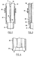
- FIG. 1 a container 1 having a body 2 forming reservoir, of which only the upper end can be seen in the drawing, defining a neck 3 on which a support is snapped 4.
- the support 4 guides in sliding, along an axis X, a push button 5 and serves mounting a removable protective cover 6, covering the push button 5 before the first use.
- the support 4 includes a sealing skirt 7 which is applied in a sealed manner on the inside surface of the neck 3.
- the sealing skirt 7 is extended radially, on the one hand towards the outside by fixing lugs 8 snapped onto an annular bead 9 of the neck 3, and on the other hand inward by a stepped wall 10 defining a nozzle 12 used for connection of a dip tube 13, partially shown in the drawing.
- An outer skirt 15 and a guide skirt 16 are made in one piece by plastic molding with the sealing skirt 7, the fixing lugs 8 and the stepped wall 10.
- the outer skirt 15 extends around the neck 3 of the container and has a shoulder 17 on which the protective cover 6 is supported.
- the upper edge 18 of the outer skirt 15 retains the push button 5 at rest, as will be explained below.
- the support 4 comprises an inner skirt 20 constituted by an attached piece, having a shoulder lower end 21, forcibly engaged in the stepped wall 10.
- the internal skirt 20 has a substantially tapered upper end, provided with openings 22, as can be seen more particularly in FIGS. 2 and 3.
- openings 22 are in the example described in the form of slots oriented along the X axis, extended downward by grooves 25 extending over the radially inner surface of the inner skirt 20 until a step 26.
- a double annular sealing lip 24 is produced in one piece with the inner skirt 20 by plastic molding.
- the push button 5 has an outer skirt 30, provided at its end lower of teeth 31, the latter abutting against the upper edge 18 of the outer skirt 15 of the support 4 when the push button 5 is at rest in position high, as shown in Figure 1.
- the push button 5 has a central duct 32, of axis X, and a skirt tubular 33 concentric, defining around the central duct 32 a pumping 34 annular.
- the outer skirt 30, the tubular skirt 33 and the central duct 32 are produced in one piece by molding plastic material with a dispensing nozzle 35, communicating internally with the central duct 32.
- the latter has, at its lower end, radial openings 36.
- the lower end of the tubular skirt 33 forms a sealing lip 37, extending slightly radially outward, as shown more particularly in Figure 4.
- the guide skirt 16 of the support 4 has a slight shrinkage in the lower part annular 41 on its radially inner surface.
- the interior of the container is thus isolated from the ambient air, which is favorable for a good conservation of the product.
- An air intake orifice 42 is made in the bottom of this groove to allow air to re-enter the container as it is emptied.
- the inner skirt 20 is used for mounting a membrane 50 having a part central unit 51 in the form of a sleeve, axis X, open at its upper end and closed at its lower end by a bottom 52.
- This central part 51 is extended radially outwards by a lip flexible annular 53, as can be seen more particularly in FIGS. 5 and 6.
- This flexible lip 53 forms, by connecting with the central part 51, a annular groove 54 into which the inner skirt 20 is inserted at its end upper, until taking support by its free edge in the bottom of said groove.
- the flexible lip (53) is made so as to slightly tighten the skirt interior 20.
- the height of the flexible lip 53 is greater than that of the openings 22 and the flexible lip 53 is suitable for applying at rest in a sealed manner by its surface inner 56 against the radially outer surface of the inner skirt 20 below openings 22, as shown in Figure 1.
- the flexible lip 53 can deform radially outward to allow to the product to gain the pumping chamber 34, as will be explained below.
- the membrane 50 comprises, at the opening of its central part 51, non-symmetrical reliefs of revolution around the X axis, namely in the example in particular bosses 55 whose function will be specified below.
- these bosses 55 are three in number, being evenly distributed angularly around the X axis, as can be seen in the figure 6.
- Each of these bosses 55 protrudes from the radially inner surface of the central part 51 along approximately half (before its mounting in the pump) of the height of the latter from its upper end and extends radially outwards on the upper face of the membrane 50 up to substantially above of the groove 54, as can be seen in FIG. 5.
- Each of the bosses 55 further presents, when observed in section in a transverse section plane, a convex section towards the X axis, as shown in the figure 6.
- the inner surface of the central part 51 of the membrane has a upper portion 70 slightly conical towards the bottom 52.
- the bosses 55 are produced on this conical portion 70, as can be see in figure 5.
- the conical surface 70 is connected by a recess 71 directed inwards to a cylindrical surface 72 of revolution around the axis X.
- the outer surface of the central part 51 of the membrane has a conical portion 73 parallel to the conical upper portion 70, which is connected by a step 74 parallel to step 71, to a surface 75 formed by a alternating sectors 76 and 77 cylindrical of revolution around the X axis, presenting different diameters.
- the sectors 77 at number of two, extend over 90 ° each, are diametrically opposed, and have a diameter smaller than sectors 76.
- the sectors 77 define with the cylindrical interior surface 72 two zones diametrically opposite thinned 78s, the function of which will be specified below.
- the sectors 76 are joined by a band 79 extending on the underside of the bottom 52 and whose sides 80 are parallel, as can be seen in FIG. 8.
- the inner surface 56 of the flexible lip 53 is conical, converging towards the top, as can be seen in Figure 5.
- the outer surface of the flexible lip 53 has, from its end lower, a lower portion 81 substantially cylindrical of revolution around the X axis, then a conical upper portion 82 diverging upwards, this portion conical 82 connecting by a shoulder 83 to an annular rib 84.
- the annular part 85 which joins the lip flexible 53 at the central part 51 is relatively wide and thick, which allows good immobilize the upper end of the central part 51 relative to the skirt interior 20 when the central part 51 is stretched.
- the annular part 85 is approximately 2 times more wide than thick, outside the bosses 55.
- the thickness ei of the bottom 52 is in the example described substantially the same as the thickness e 2 of the side wall of the central part 51 between the surfaces 73 and 70, outside the bosses 55.
- the thickness e 3 of the central part 51 measured between the surfaces 72 and 77 is approximately 0.75 times the thickness e 2 , in the embodiment described.
- the thickness e 1 is 0.55 mm
- the thickness e 2 is 0.55 mm
- the thickness e 3 is 0.4 mm (thicknesses measured before mounting the diaphragm in the pump).
- the length of the central part 51 of the membrane is approximately 3 times the initial length l 0 of the central part 51, that is to say that l elongation reaches 200%.
- the length lo measured between the bottom of the groove 54 and the upper face of the bottom 52 is approximately 3 mm and when the membrane is in place in the pump and the push button at rest as shown in Figure 1, the length of the central part 51 is 9 mm about.
- the length of the central part 51 reaches an elongation of 350%.
- the length of the central part 51 is then, for the example considered, 13.5 mm, the stroke of the push button 5 down being 4.5 mm.
- the central duct 32 of the push button 5 is inserted into the central part 51 of the membrane 50 until it bears, by its end lower, against the bottom 52 of the membrane 50, as illustrated in FIG. 1.
- bosses 55 then apply, in the example described, against the surface cylindrical of revolution of the central duct 32. However, it is not necessary to in general, that the bosses 55 apply to the central duct 32 when the push button is at rest.
- the double sealing lip 24 is applied sealingly to the surface radially inner of the tubular skirt 33, whatever the upward movement or down from push button 5.
- the flexible lip comes to rest by its internal surface 56 on the skirt interior 20.
- the support 4, the push button 5 and the membrane 50 constitute a pump the operation of which is as follows.
- the central duct 32 drives down the bottom 52 of the membrane 50, which deforms elastically by stretching to accompany the movement of lowering of the central duct 32.
- the pump is here assumed to be primed, that is to say that the pumping chamber 34 is filled with product.
- the product contained in the pumping chamber 34 is driven between the central duct 32 and the part central 51 of the membrane and gains the radial openings 36 of the central duct 32, then the dispensing nozzle 35.
- the flexible lip 53 is applied in a sealed manner by its internal surface 56 on the inner skirt 20 during the downward movement of the push button 5.
- the sealing lip 37 of the tubular skirt 33 of the push button 5 ceases, when it reaches the annular withdrawal 41 after a certain driving stroke of the push button 5, to be applied in a sealed manner on the guide skirt 16, allowing communication between the inside of the container and the outside, by through the air intake orifice 42 and the clearance existing between the guide skirt 16 and the tubular skirt 33.
- the bosses 55 form passages between them for the product and prevent the formation of a sealed annular zone between the central duct 32 and the central part 51 of the membrane 50 which could not be overcome by the pressure of the product, so that the product can flow to the radial openings 36, the membrane 50 being able deviate slightly from the central duct 32 in the vicinity of the upper end of the openings 36 under the effect of product pressure.
- the existence of the thinned zones 78 favors the outward deformation of the side wall of the central part 51 to allow the product to enter the radial openings 36.
- the existence of the offset 71 allows the product to descend more easily along the central duct 32 to the radial openings 36, without risk of blockage of the circulation of the product through the membrane 50.
- the bosses 55 tend to keep the central duct 32 coaxial with the skirt inner 20 and to guarantee the attachment of the membrane to the inner skirt 20.
- the central part 51 can have in apart from the latter a relatively large thickness of material which allows to sufficiently stretch the central part 51 during the fitting of the membrane 50 in the pump to obtain the restoring force making it possible to return safely blocking the push button 5 upwards.
- the central part 51 of the membrane 50 closes the radial openings 36 and the depression which is created in the pumping chamber 34 causes the flexible lip 53 to separate from the skirt interior 20 and a product inlet from the container.
- the recess 71 is located above the upper end of the openings radial 36 so that during the movement of the return of the push button 5, the surface 72 of the central part 51 can close the radial openings 36.
- the product reaches the pumping chamber 34 by flowing through the grooves 25 of the inner skirt 20 along the central part 51 of the membrane 50, crossing the inner skirt 20 in favor of the openings 22, then bypassing the flexible lip 53 and going up outside the latter, as illustrated in Figure 10.
- the relatively small thickness of the bottom 52 makes it possible to prevent the elastomeric material in which the membrane is made does not constitute, under the action from the thrust of the central duct 32, a bead which when applied to the surface interior of the interior skirt 20 could cause detrimental friction to the correct operation of the pump.
- This spring is housed inside the inner skirt 20, works in compression, and is supported at its lower end on the recess 26 and at its upper end on the underside of the bottom 52 of the membrane.
- This valve can be produced for example by means of a ball 91 shown in broken lines in Figure 8, the tip 12 serving as a seat.
- Reliefs 92 are produced on the inner surface of the inner skirt to retain the ball 91 near its seat.
- the ball 91 is chosen to be very rough so as to create a leak allowing not to block the downward movement of the central part of the membrane during dispensing a dose of product.
- the ball 91 makes it possible to prime the pump by actuating a small number of times the push button.
- the membrane can also be made of at least two materials different.
- a helical spring is arranged around the central duct and bears at its lower end on the upper end of the membrane and at its upper end on the push button 5.
Landscapes
- Reciprocating Pumps (AREA)
- Closures For Containers (AREA)
- Containers And Packaging Bodies Having A Special Means To Remove Contents (AREA)
- Separation Using Semi-Permeable Membranes (AREA)
- External Artificial Organs (AREA)
Applications Claiming Priority (2)
| Application Number | Priority Date | Filing Date | Title |
|---|---|---|---|
| FR9905772 | 1999-05-06 | ||
| FR9905772A FR2793223B1 (fr) | 1999-05-06 | 1999-05-06 | Pompe a membrane comportant, sur au moins un secteur de sa peripherie, une zone de deformation preferentielle et recipient ainsi equipe |
Publications (2)
| Publication Number | Publication Date |
|---|---|
| EP1050480A1 true EP1050480A1 (de) | 2000-11-08 |
| EP1050480B1 EP1050480B1 (de) | 2004-12-15 |
Family
ID=9545288
Family Applications (1)
| Application Number | Title | Priority Date | Filing Date |
|---|---|---|---|
| EP00401241A Expired - Lifetime EP1050480B1 (de) | 1999-05-06 | 2000-05-05 | Membranpumpe mit einer zumindest in einem Teilbereich der Peripherie befindlichen, bevorzugten Verformungszone, und damit ausgerüsteter Behälter |
Country Status (8)
| Country | Link |
|---|---|
| US (2) | US6299029B1 (de) |
| EP (1) | EP1050480B1 (de) |
| JP (1) | JP3398645B2 (de) |
| AT (1) | ATE284824T1 (de) |
| CA (1) | CA2308858C (de) |
| DE (1) | DE60016663T2 (de) |
| ES (1) | ES2233303T3 (de) |
| FR (1) | FR2793223B1 (de) |
Cited By (1)
| Publication number | Priority date | Publication date | Assignee | Title |
|---|---|---|---|---|
| WO2015018758A3 (de) * | 2013-08-07 | 2015-04-09 | Aptar Radolfzell Gmbh | Pumpeinrichtung und spender für flüssige oder pastöse medien |
Families Citing this family (3)
| Publication number | Priority date | Publication date | Assignee | Title |
|---|---|---|---|---|
| DE10334032B4 (de) * | 2003-07-18 | 2005-06-23 | Ing. Erich Pfeiffer Gmbh | Ventileinrichtung |
| US8197231B2 (en) | 2005-07-13 | 2012-06-12 | Purity Solutions Llc | Diaphragm pump and related methods |
| US9610392B2 (en) | 2012-06-08 | 2017-04-04 | Fresenius Medical Care Holdings, Inc. | Medical fluid cassettes and related systems and methods |
Citations (2)
| Publication number | Priority date | Publication date | Assignee | Title |
|---|---|---|---|---|
| US4890773A (en) * | 1988-03-15 | 1990-01-02 | Calmar, Inc. | Viscous product dispenser |
| FR2728809A1 (fr) | 1995-01-04 | 1996-07-05 | Daniel Crosnier | Dispositif doseur adaptable sur des contenants divers |
Family Cites Families (1)
| Publication number | Priority date | Publication date | Assignee | Title |
|---|---|---|---|---|
| FR2786162B1 (fr) * | 1998-11-20 | 2001-02-09 | Oreal | Pompe et recipient ainsi equipe |
-
1999
- 1999-05-06 FR FR9905772A patent/FR2793223B1/fr not_active Expired - Fee Related
-
2000
- 2000-05-04 US US09/564,667 patent/US6299029B1/en not_active Ceased
- 2000-05-05 ES ES00401241T patent/ES2233303T3/es not_active Expired - Lifetime
- 2000-05-05 EP EP00401241A patent/EP1050480B1/de not_active Expired - Lifetime
- 2000-05-05 CA CA002308858A patent/CA2308858C/fr not_active Expired - Fee Related
- 2000-05-05 AT AT00401241T patent/ATE284824T1/de not_active IP Right Cessation
- 2000-05-05 DE DE60016663T patent/DE60016663T2/de not_active Expired - Lifetime
- 2000-05-08 JP JP2000134867A patent/JP3398645B2/ja not_active Expired - Fee Related
-
2003
- 2003-03-10 US US10/383,545 patent/USRE40219E1/en not_active Expired - Lifetime
Patent Citations (2)
| Publication number | Priority date | Publication date | Assignee | Title |
|---|---|---|---|---|
| US4890773A (en) * | 1988-03-15 | 1990-01-02 | Calmar, Inc. | Viscous product dispenser |
| FR2728809A1 (fr) | 1995-01-04 | 1996-07-05 | Daniel Crosnier | Dispositif doseur adaptable sur des contenants divers |
Cited By (1)
| Publication number | Priority date | Publication date | Assignee | Title |
|---|---|---|---|---|
| WO2015018758A3 (de) * | 2013-08-07 | 2015-04-09 | Aptar Radolfzell Gmbh | Pumpeinrichtung und spender für flüssige oder pastöse medien |
Also Published As
| Publication number | Publication date |
|---|---|
| ES2233303T3 (es) | 2005-06-16 |
| JP2001003856A (ja) | 2001-01-09 |
| ATE284824T1 (de) | 2005-01-15 |
| CA2308858A1 (fr) | 2000-11-06 |
| DE60016663T2 (de) | 2005-12-08 |
| EP1050480B1 (de) | 2004-12-15 |
| US6299029B1 (en) | 2001-10-09 |
| DE60016663D1 (de) | 2005-01-20 |
| FR2793223B1 (fr) | 2001-07-27 |
| JP3398645B2 (ja) | 2003-04-21 |
| FR2793223A1 (fr) | 2000-11-10 |
| CA2308858C (fr) | 2005-07-12 |
| USRE40219E1 (en) | 2008-04-08 |
Similar Documents
| Publication | Publication Date | Title |
|---|---|---|
| CA2262135C (fr) | Ensemble de conditionnement et de distribution d'un produit liquide | |
| EP2579993B1 (de) | Pumpe zur ausgabe eines produkts mit einem gleitkolben in der messkammer | |
| EP1344571B1 (de) | Verpackung- und Abgabeeinheit von Medien, insbesondere von flüssigen Proben | |
| CA2290218C (fr) | Pompe et recipient ainsi equipe | |
| EP0623060A1 (de) | Vordruckpumpe. | |
| CA2324489C (fr) | Pompe destinee a equiper un recipient, comportant une membrane elastiquement deformable a l'exterieur de la chambre de pompage | |
| EP1472007B1 (de) | Spender für fliessfähige medien mit einer pumpe | |
| EP0960829B1 (de) | Ventil sowie Aufbewahrungs- und Ausgabevorrichtung mit einem solchen Ventil | |
| FR2979099A1 (fr) | Tete de distribution de produit pour un recipient et dispositif de distribution associe | |
| FR2816375A1 (fr) | Pompe pour la distribution d'un produit, notamment un produit cosmetique ou de soin | |
| FR2928357A1 (fr) | Obturateur d'organe de distribution de produit fluide. | |
| FR2925032A1 (fr) | Valve pour recipient sous pression de stockage et de distribution de produit et recipient pourvu d'une telle valve | |
| EP1050480B1 (de) | Membranpumpe mit einer zumindest in einem Teilbereich der Peripherie befindlichen, bevorzugten Verformungszone, und damit ausgerüsteter Behälter | |
| EP1070670B1 (de) | Membranpumpe und damit ausgerüsteter Behälter | |
| EP1125638B1 (de) | Pumpe mit einem beweglichen Teil, der einen zentralen Kanal und eine auf dem zentralen Kanal befestigte Membrane enthält, und Behälter mit einer solchen Pumpe | |
| EP1616632B1 (de) | Pumpe zum Ausbringen eines Produkts in verschiedenen Sprühpositionen und entsprechender Behälter | |
| EP1074479B1 (de) | Membranpumpe für Behälter | |
| EP1475012B1 (de) | Vorrichtug zum Aufbewahren und Auftragen eines Produktes | |
| FR2803831A1 (fr) | Dispositif d'etancheite pour recipient | |
| FR2539330A1 (fr) | Dispositif d'actionnement pour valves de recipients pressurises | |
| FR2841538A1 (fr) | Ensemble de conditionnement et de distribution d'un produit |
Legal Events
| Date | Code | Title | Description |
|---|---|---|---|
| PUAI | Public reference made under article 153(3) epc to a published international application that has entered the european phase |
Free format text: ORIGINAL CODE: 0009012 |
|
| 17P | Request for examination filed |
Effective date: 20000512 |
|
| AK | Designated contracting states |
Kind code of ref document: A1 Designated state(s): AT BE CH CY DE DK ES FI FR GB GR IE IT LI LU MC NL PT SE |
|
| AX | Request for extension of the european patent |
Free format text: AL;LT;LV;MK;RO;SI |
|
| AKX | Designation fees paid |
Free format text: AT BE CH CY DE DK ES FI FR GB GR IE IT LI LU MC NL PT SE |
|
| 17Q | First examination report despatched |
Effective date: 20020801 |
|
| GRAP | Despatch of communication of intention to grant a patent |
Free format text: ORIGINAL CODE: EPIDOSNIGR1 |
|
| GRAS | Grant fee paid |
Free format text: ORIGINAL CODE: EPIDOSNIGR3 |
|
| GRAA | (expected) grant |
Free format text: ORIGINAL CODE: 0009210 |
|
| AK | Designated contracting states |
Kind code of ref document: B1 Designated state(s): AT BE CH CY DE DK ES FI FR GB GR IE IT LI LU MC NL PT SE |
|
| PG25 | Lapsed in a contracting state [announced via postgrant information from national office to epo] |
Ref country code: FI Free format text: LAPSE BECAUSE OF FAILURE TO SUBMIT A TRANSLATION OF THE DESCRIPTION OR TO PAY THE FEE WITHIN THE PRESCRIBED TIME-LIMIT Effective date: 20041215 Ref country code: IE Free format text: LAPSE BECAUSE OF FAILURE TO SUBMIT A TRANSLATION OF THE DESCRIPTION OR TO PAY THE FEE WITHIN THE PRESCRIBED TIME-LIMIT Effective date: 20041215 Ref country code: AT Free format text: LAPSE BECAUSE OF FAILURE TO SUBMIT A TRANSLATION OF THE DESCRIPTION OR TO PAY THE FEE WITHIN THE PRESCRIBED TIME-LIMIT Effective date: 20041215 Ref country code: NL Free format text: LAPSE BECAUSE OF FAILURE TO SUBMIT A TRANSLATION OF THE DESCRIPTION OR TO PAY THE FEE WITHIN THE PRESCRIBED TIME-LIMIT Effective date: 20041215 |
|
| REG | Reference to a national code |
Ref country code: GB Ref legal event code: FG4D Free format text: NOT ENGLISH Ref country code: CH Ref legal event code: EP |
|
| REG | Reference to a national code |
Ref country code: IE Ref legal event code: FG4D Free format text: FRENCH |
|
| REF | Corresponds to: |
Ref document number: 60016663 Country of ref document: DE Date of ref document: 20050120 Kind code of ref document: P |
|
| PG25 | Lapsed in a contracting state [announced via postgrant information from national office to epo] |
Ref country code: DK Free format text: LAPSE BECAUSE OF FAILURE TO SUBMIT A TRANSLATION OF THE DESCRIPTION OR TO PAY THE FEE WITHIN THE PRESCRIBED TIME-LIMIT Effective date: 20050315 Ref country code: GR Free format text: LAPSE BECAUSE OF FAILURE TO SUBMIT A TRANSLATION OF THE DESCRIPTION OR TO PAY THE FEE WITHIN THE PRESCRIBED TIME-LIMIT Effective date: 20050315 Ref country code: SE Free format text: LAPSE BECAUSE OF FAILURE TO SUBMIT A TRANSLATION OF THE DESCRIPTION OR TO PAY THE FEE WITHIN THE PRESCRIBED TIME-LIMIT Effective date: 20050315 |
|
| GBT | Gb: translation of ep patent filed (gb section 77(6)(a)/1977) |
Effective date: 20050218 |
|
| PG25 | Lapsed in a contracting state [announced via postgrant information from national office to epo] |
Ref country code: CY Free format text: LAPSE BECAUSE OF FAILURE TO SUBMIT A TRANSLATION OF THE DESCRIPTION OR TO PAY THE FEE WITHIN THE PRESCRIBED TIME-LIMIT Effective date: 20050505 Ref country code: LU Free format text: LAPSE BECAUSE OF NON-PAYMENT OF DUE FEES Effective date: 20050505 |
|
| PG25 | Lapsed in a contracting state [announced via postgrant information from national office to epo] |
Ref country code: LI Free format text: LAPSE BECAUSE OF NON-PAYMENT OF DUE FEES Effective date: 20050531 Ref country code: MC Free format text: LAPSE BECAUSE OF NON-PAYMENT OF DUE FEES Effective date: 20050531 Ref country code: BE Free format text: LAPSE BECAUSE OF NON-PAYMENT OF DUE FEES Effective date: 20050531 Ref country code: CH Free format text: LAPSE BECAUSE OF NON-PAYMENT OF DUE FEES Effective date: 20050531 |
|
| NLV1 | Nl: lapsed or annulled due to failure to fulfill the requirements of art. 29p and 29m of the patents act | ||
| REG | Reference to a national code |
Ref country code: ES Ref legal event code: FG2A Ref document number: 2233303 Country of ref document: ES Kind code of ref document: T3 |
|
| REG | Reference to a national code |
Ref country code: IE Ref legal event code: FD4D |
|
| PLBE | No opposition filed within time limit |
Free format text: ORIGINAL CODE: 0009261 |
|
| STAA | Information on the status of an ep patent application or granted ep patent |
Free format text: STATUS: NO OPPOSITION FILED WITHIN TIME LIMIT |
|
| BERE | Be: lapsed |
Owner name: L'OREAL Effective date: 20050531 |
|
| 26N | No opposition filed |
Effective date: 20050916 |
|
| REG | Reference to a national code |
Ref country code: CH Ref legal event code: PL |
|
| BERE | Be: lapsed |
Owner name: L'*OREAL Effective date: 20050531 |
|
| PG25 | Lapsed in a contracting state [announced via postgrant information from national office to epo] |
Ref country code: PT Free format text: LAPSE BECAUSE OF NON-PAYMENT OF DUE FEES Effective date: 20050515 |
|
| PGFP | Annual fee paid to national office [announced via postgrant information from national office to epo] |
Ref country code: ES Payment date: 20120607 Year of fee payment: 13 |
|
| PGFP | Annual fee paid to national office [announced via postgrant information from national office to epo] |
Ref country code: DE Payment date: 20130515 Year of fee payment: 14 Ref country code: GB Payment date: 20130501 Year of fee payment: 14 |
|
| PGFP | Annual fee paid to national office [announced via postgrant information from national office to epo] |
Ref country code: IT Payment date: 20130515 Year of fee payment: 14 Ref country code: FR Payment date: 20130531 Year of fee payment: 14 |
|
| REG | Reference to a national code |
Ref country code: DE Ref legal event code: R119 Ref document number: 60016663 Country of ref document: DE |
|
| GBPC | Gb: european patent ceased through non-payment of renewal fee |
Effective date: 20140505 |
|
| REG | Reference to a national code |
Ref country code: FR Ref legal event code: ST Effective date: 20150130 |
|
| REG | Reference to a national code |
Ref country code: DE Ref legal event code: R119 Ref document number: 60016663 Country of ref document: DE Effective date: 20141202 |
|
| PG25 | Lapsed in a contracting state [announced via postgrant information from national office to epo] |
Ref country code: DE Free format text: LAPSE BECAUSE OF NON-PAYMENT OF DUE FEES Effective date: 20141202 Ref country code: IT Free format text: LAPSE BECAUSE OF NON-PAYMENT OF DUE FEES Effective date: 20140505 |
|
| PG25 | Lapsed in a contracting state [announced via postgrant information from national office to epo] |
Ref country code: GB Free format text: LAPSE BECAUSE OF NON-PAYMENT OF DUE FEES Effective date: 20140505 Ref country code: FR Free format text: LAPSE BECAUSE OF NON-PAYMENT OF DUE FEES Effective date: 20140602 |
|
| REG | Reference to a national code |
Ref country code: ES Ref legal event code: FD2A Effective date: 20150630 |
|
| PG25 | Lapsed in a contracting state [announced via postgrant information from national office to epo] |
Ref country code: ES Free format text: LAPSE BECAUSE OF NON-PAYMENT OF DUE FEES Effective date: 20140506 |