EP1050678A2 - Leitschaufel - Google Patents
Leitschaufel Download PDFInfo
- Publication number
- EP1050678A2 EP1050678A2 EP00303787A EP00303787A EP1050678A2 EP 1050678 A2 EP1050678 A2 EP 1050678A2 EP 00303787 A EP00303787 A EP 00303787A EP 00303787 A EP00303787 A EP 00303787A EP 1050678 A2 EP1050678 A2 EP 1050678A2
- Authority
- EP
- European Patent Office
- Prior art keywords
- exhaust
- vanes
- nozzle
- vane
- leading
- Prior art date
- Legal status (The legal status is an assumption and is not a legal conclusion. Google has not performed a legal analysis and makes no representation as to the accuracy of the status listed.)
- Granted
Links
- 241001481833 Coryphaena hippurus Species 0.000 claims abstract description 21
- 238000007599 discharging Methods 0.000 claims abstract description 4
- 238000000034 method Methods 0.000 claims description 10
- 238000009792 diffusion process Methods 0.000 description 7
- 239000007789 gas Substances 0.000 description 6
- 230000000694 effects Effects 0.000 description 4
- 238000000926 separation method Methods 0.000 description 3
- 230000008030 elimination Effects 0.000 description 2
- 238000003379 elimination reaction Methods 0.000 description 2
- 241000145637 Lepturus Species 0.000 description 1
- 230000001133 acceleration Effects 0.000 description 1
- 230000002411 adverse Effects 0.000 description 1
- 230000005465 channeling Effects 0.000 description 1
- 239000000567 combustion gas Substances 0.000 description 1
- 239000000446 fuel Substances 0.000 description 1
- 238000002156 mixing Methods 0.000 description 1
- 239000000203 mixture Substances 0.000 description 1
- 230000035945 sensitivity Effects 0.000 description 1
Images

Classifications
-
- B—PERFORMING OPERATIONS; TRANSPORTING
- B64—AIRCRAFT; AVIATION; COSMONAUTICS
- B64D—EQUIPMENT FOR FITTING IN OR TO AIRCRAFT; FLIGHT SUITS; PARACHUTES; ARRANGEMENT OR MOUNTING OF POWER PLANTS OR PROPULSION TRANSMISSIONS IN AIRCRAFT
- B64D33/00—Arrangement in aircraft of power plant parts or auxiliaries not otherwise provided for
- B64D33/04—Arrangement in aircraft of power plant parts or auxiliaries not otherwise provided for of exhaust outlets or jet pipes
-
- F—MECHANICAL ENGINEERING; LIGHTING; HEATING; WEAPONS; BLASTING
- F01—MACHINES OR ENGINES IN GENERAL; ENGINE PLANTS IN GENERAL; STEAM ENGINES
- F01D—NON-POSITIVE DISPLACEMENT MACHINES OR ENGINES, e.g. STEAM TURBINES
- F01D5/00—Blades; Blade-carrying members; Heating, heat-insulating, cooling or antivibration means on the blades or the members
- F01D5/12—Blades
- F01D5/14—Form or construction
- F01D5/141—Shape, i.e. outer, aerodynamic form
-
- F—MECHANICAL ENGINEERING; LIGHTING; HEATING; WEAPONS; BLASTING
- F05—INDEXING SCHEMES RELATING TO ENGINES OR PUMPS IN VARIOUS SUBCLASSES OF CLASSES F01-F04
- F05D—INDEXING SCHEME FOR ASPECTS RELATING TO NON-POSITIVE-DISPLACEMENT MACHINES OR ENGINES, GAS-TURBINES OR JET-PROPULSION PLANTS
- F05D2240/00—Components
- F05D2240/10—Stators
- F05D2240/12—Fluid guiding means, e.g. vanes
- F05D2240/128—Nozzles
-
- F—MECHANICAL ENGINEERING; LIGHTING; HEATING; WEAPONS; BLASTING
- F05—INDEXING SCHEMES RELATING TO ENGINES OR PUMPS IN VARIOUS SUBCLASSES OF CLASSES F01-F04
- F05D—INDEXING SCHEME FOR ASPECTS RELATING TO NON-POSITIVE-DISPLACEMENT MACHINES OR ENGINES, GAS-TURBINES OR JET-PROPULSION PLANTS
- F05D2250/00—Geometry
- F05D2250/70—Shape
-
- F—MECHANICAL ENGINEERING; LIGHTING; HEATING; WEAPONS; BLASTING
- F05—INDEXING SCHEMES RELATING TO ENGINES OR PUMPS IN VARIOUS SUBCLASSES OF CLASSES F01-F04
- F05D—INDEXING SCHEME FOR ASPECTS RELATING TO NON-POSITIVE-DISPLACEMENT MACHINES OR ENGINES, GAS-TURBINES OR JET-PROPULSION PLANTS
- F05D2250/00—Geometry
- F05D2250/70—Shape
- F05D2250/71—Shape curved
-
- F—MECHANICAL ENGINEERING; LIGHTING; HEATING; WEAPONS; BLASTING
- F05—INDEXING SCHEMES RELATING TO ENGINES OR PUMPS IN VARIOUS SUBCLASSES OF CLASSES F01-F04
- F05D—INDEXING SCHEME FOR ASPECTS RELATING TO NON-POSITIVE-DISPLACEMENT MACHINES OR ENGINES, GAS-TURBINES OR JET-PROPULSION PLANTS
- F05D2250/00—Geometry
- F05D2250/70—Shape
- F05D2250/71—Shape curved
- F05D2250/711—Shape curved convex
-
- Y—GENERAL TAGGING OF NEW TECHNOLOGICAL DEVELOPMENTS; GENERAL TAGGING OF CROSS-SECTIONAL TECHNOLOGIES SPANNING OVER SEVERAL SECTIONS OF THE IPC; TECHNICAL SUBJECTS COVERED BY FORMER USPC CROSS-REFERENCE ART COLLECTIONS [XRACs] AND DIGESTS
- Y02—TECHNOLOGIES OR APPLICATIONS FOR MITIGATION OR ADAPTATION AGAINST CLIMATE CHANGE
- Y02T—CLIMATE CHANGE MITIGATION TECHNOLOGIES RELATED TO TRANSPORTATION
- Y02T50/00—Aeronautics or air transport
- Y02T50/60—Efficient propulsion technologies, e.g. for aircraft
Definitions
- the present invention relates generally to gas turbine engines, and, more specifically, to exhaust nozzles therefor.
- a typical military fighter aircraft includes a turbofan gas turbine engine having an augmenter or afterburner for producing additional thrust when desired.
- the engine has high specific thrust and operates at a high pressure ratio during takeoff for providing exceptional acceleration.
- the exhaust nozzle therefor is typically variable in the form of a converging-diverging (CD) exhaust nozzle.
- the nozzle throat varies in flow area between maximum and minimum values for maximizing performance of the engine throughout its entire flight envelope.
- the high pressure ratio combustion gases exhausted from the engine may be choked at the throat at sonic velocity, and are subsonic in the converging nozzle and supersonic in the diverging nozzle.
- the typical CD exhaust nozzle merely directs the exhaust in the axial downstream direction for propelling the aircraft forward in flight. Improvements in aircraft performance may be obtained by turning the exhaust in different directions.
- STOL Short Takeoff and Landing
- STOVL Short Takeoff/Vertical Landing
- STOL Short Takeoff and Landing
- STOVL Short Takeoff/Vertical Landing
- STOL Short Takeoff and Landing
- STOVL Short Takeoff/Vertical Landing
- the secondary exhaust nozzle must be integrated with the engine outlet duct in a compact and aerodynamically efficient package.
- the secondary exhaust duct should be as short as possible while maximizing turning efficiency of the exhaust as it is discharged axially from the engine and diverted radially outwardly.
- the secondary nozzle includes two dimensional (2-D) cascade turning vanes located at the discharge end of the exhaust duct.
- These cascade vanes may have a simple, symmetrical teardrop profile between which the exhaust is turned and redirected from the aircraft.
- These cascade vanes may also have a simple crescent airfoil profile in the direction of flow turning.
- cascade vanes are also found in thrust reversers for temporarily turning engine exhaust for use in braking aircraft speed during landings.
- Efficiency of cascade-vane thrust reversers in a typical commercial aircraft is not a critical design objective since they merely provide auxiliary braking, and since the engines operate at low pressure ratios.
- cascade vane design is critical to operation since the engines have high specific thrust and high pressure ratios during takeoff, and are sized by the required performance of the secondary exhaust nozzle.
- An inefficient secondary exhaust nozzle requires a larger engine which is heavier and more expensive, and reduces the overall performance of the aircraft.
- An efficient secondary exhaust nozzle permits corresponding reduction in size of the engine and improves the overall performance of the aircraft.
- An exhaust nozzle includes cascade vanes mounted in a duct for discharging exhaust.
- the vanes have a dolphin profile which is effective for turning subsonically the exhaust near leading edges of the vanes, and then diffusing supersonically the exhaust downstream therefrom. Thrust efficiency of the vanes is therefore shifted to lower pressure ratios during operation for improving performance of the nozzle.
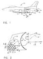
- Illustrated in Figure 1 is a high performance, military fighter/attack aircraft 10 having one or more turbofan gas turbine engines 12 mounted therein.
- the engine may have any conventional configuration such as a low bypass, turbofan engine from which is discharged during operation exhaust gases 14 for producing propulsion thrust to power the aircraft in flight.
- a conventional augmenter or afterburner 16 Disposed downstream from the engine inside the aircraft is a conventional augmenter or afterburner 16 which may be used to introduce additional fuel into the exhaust 14 for wet or reheat operation to provide additional thrust when desired.
- a variable area CD main exhaust nozzle 18 Disposed in turn downstream from the afterburner 16 is a variable area CD main exhaust nozzle 18 which directs the exhaust 14 in the axially aft or downstream direction for propelling the aircraft forward during takeoff and in flight.
- the aircraft further includes a plurality of secondary exhaust nozzles 20 suitably disposed in flow communication with the engine 12 for selectively receiving at least a portion of the exhaust 14 for turning or redirection downwardly.
- the secondary nozzle 20 includes a short flow duct 22 in the exemplary form of a tubular elbow for redirecting the exhaust 14 initially discharged axially from the engine in a lateral direction oblique to the centerline axis of the engine and typically downwardly.
- the exhaust duct 22 may be suitably pivoted to the engine or aircraft body as warranted for redirecting the exhaust over a range of angles including, for example, the axial downstream direction up to and including normal or perpendicular therefrom.
- Figures 1 and 2 show the nozzle 20 directed downwardly for producing a downward thrust to raise the aircraft upwardly.
- the secondary exhaust nozzle 20 may have any conventional form for redirecting the exhaust 14 when desired in propelling the aircraft in flight.
- the secondary nozzle 20 includes a plurality of exhaust vanes 24, as initially shown in Figure 2, which are laterally spaced apart from each other to define respective nozzle flow passages 26 at the distal or outlet end of the duct 22.
- the duct 22 itself may be an elbow up to about 90 degrees for initially turning the exhaust 14 in the desired direction.
- the cascade vanes 24 complete the required turning of the exhaust with enhanced efficiency for improving performance of the aircraft.
- each of the vanes 24 includes a first or upper side or surface 28 and an opposite second or lower surface or side 30 extending axially between opposite leading and trailing edges 32,34.
- each of the vanes 24 has a precisely configured convex crown 36 spaced aft from the leading edge 32 along the upper side 28 to define a cascade exhaust vane having a generally dolphin profile or configuration.
- each of the nozzle passages 26 includes a forward part or zone 38 extending axially or chordally from the vane leading edges 32 to an effective throat 40 which laterally bridges the trailing edge 34 of one vane and the crown 36 of an adjacent vane.
- Each nozzle passage 26 also includes an aft part or zone 42 extending aft from the throat 40 to the vane trailing edges 34, in particular along the vane upper sides 28.
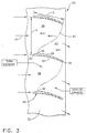
- the dolphin vanes 24 illustrated in Figure 3 in cooperation with the nozzle passages 26 defined therebetween effect an improved method of turning the exhaust 14 through the secondary nozzle 20 for increasing thrust efficiency at lower pressure ratios across the vanes. Since the exhaust 14 is provided at a relatively high pressure ratio across the vanes, the exhaust is initially turned subsonically at a Mach number less than 1 near the vane leading edges 32 in the nozzle forward parts 38, and choked sonically at Mach 1 at the effective throat 40. The exhaust 14 is then diffused supersonically with a Mach No. greater than 1 in the passage aft parts 42 downstream from the throats 40.
- FIG. 2 Included in Figure 2 is an associated performance graph which plots a thrust coefficient (CFG) verses pressure ratio (PR) across the vanes. Thrust efficiency of the secondary exhaust nozzle 20 may be evaluated from the plotted trust coefficient and is indicative of the actual or realized thrust from the nozzle 20 compared to the maximum theoretical thrust therefrom.
- CFG thrust coefficient
- PR pressure ratio
- the graph indicates that the nozzle thrust efficiency is a function of the system pressure ratio as measured across the cascade vanes 24. Analysis indicates that thrust efficiency increases to a peak value as pressure ratio increases.
- Figure 2 includes a first curve 44 based on a typical subsonic cascade vane of generally crescent profile formed of primarily circular arcs. When such vanes are used in a high pressure ratio application subject to supersonic velocities, the peak thrust efficiency is found at undesirably large pressure ratios.
- a typical system pressure ratio for the high specific thrust aircraft engine illustrated in Figure 1 is greater than about 1.9 and results in supersonic exhaust flow.
- the secondary nozzle 22 is designed for a specific amount of flow turning such as about 22.5 degrees.
- the graph in Figure 2 indicates that improved thrust efficiency may be obtained in the first curve 44 at high pressure ratios substantially greater tan 2.0.
- the higher pressure ratios require a more complex, typically larger turbine engine with an attendant increase in weight and cost which are undesirable.
- a critical objective is to maximize thrust efficiency of the secondary nozzle 20 at relatively low pressure ratios for a given application.
- analysis indicates that simple, circular arc, crescent cascade vanes have limited usefulness in supersonic exhaust nozzles at relatively low pressure ratios.
- the improved dolphin vanes 24 exhibit the performance of the second curve 46 plotted generally in Figure 2 having a substantial increase in thrust efficiency at the lower pressure ratios plotted.
- Figure 4 illustrates in more particularity an exemplary embodiment of the dolphin vane 24 mounted at the outlet end of the secondary nozzle duct 22.
- the crown 36 forms a convex portion of the vane upper side 28 spaced aft from the leading edge 32.
- the vane also includes a preferably flat or straight nose 48 which extends between the leading edge 32 and the crown 36.
- the nose 48 defines an incline or grade having an inclination angle A relative to the nominal or zero angle of attack of the approaching exhaust 14 at the leading edge 32.
- Each vane 24 also includes an arcuate tail 50 extending chordally aft from the crown 36 to terminate at the trailing edge 34.
- the exhaust flow 14 initially engages each vane at its head, including the nose 48 and crown 36, and splits over the vane upper and lower sides 28,30 for flow downstream along the relatively thin tail 50.
- the upper side 28 of the tail 50 at the tailing edge 34 has an inclination angle B which is opposite to the inclination angle A of the nose 48, and is in the same direction of the desired flow turning.
- the nose 48 has an inclination angle A of about 15 degrees
- the tail 50 has an inclination angle B of about -26 degrees.
- the crown 36 is positioned well within the first half of the vane chord length C, and preferably at about 20 percent chord length from the leading edge 32. (11) In this way, the straight nose 48 and adjoining convex crown 36 are positioned directly near the vane leading edges 32 for providing means to accomplish the majority of exhaust flow turning well forward in the nozzle passages 26 along the vane upper sides 28.
- this configuration also permits tailoring of the vane tails 50 and the associated nozzle passage aft parts 42 to reduce the diverging area ratio and the associated CD nozzle effect. This biases the peak thrust efficiency closer to the lower design pressure ratio illustrated in the second curve 46 of Figure 2.
- the dolphin vanes 24 and their associated nozzle passages 26 are effective for turning the exhaust about 22.5 degrees between the leading and trailing edges 32,34 with a thrust efficiency of about 98.5 percent at a pressure ratio of about 2.06 across the vanes.
- This significant performance advantage provides a relatively high thrust efficiency for the secondary nozzle at relatively low pressure ratio for a given amount of flow turning in the nozzle.
- the high, 98.5 percent, thrust efficiency objective for the secondary exhaust nozzle 20 avoids the need for a larger, more complex, heavier, and expensive gas turbine engine which would otherwise be required for achieving the same thrust efficiency at the higher system pressure ratio using cascade vanes meeting the first curve 44 illustrated in Figure 2.
- the improved efficiency secondary exhaust nozzle 20 provides additional advantages. Any thrust lost in cascade exhaust vanes would otherwise be made up in higher engine airflows, which would result in larger and heavier engines, and correspondingly large aircraft engine bays.
- the high performance of the secondary exhaust nozzle 20 having the dolphin vanes 24 meets the desired high trust efficiency requirement for minimizing engine size for a given application.
- the cascade vanes in the secondary nozzle 20 illustrated in Figure 3 not only turn the exhaust as it flows through the nozzle passages 26, but also diffuses the exhaust prior to discharge to the atmosphere.
- the vane crowns 36 By positioning the vane crowns 36 near the vane leading edges, diffusion aft of the effective throats 40 and sonic line is substantially reduced or minimized.
- the nozzle passages 26 vary in area between the leading and trailing edges of the adjacent vanes, and in view of the relatively high pressure ratios greater than about 1.9, the nozzle passages effect individual converging-diverging (CD) nozzles.
- the exhaust flow in the forward parts 38 is subsonic, and chokes at the effective throats 40, and then becomes supersonic in the aft parts 42 wherein diffusion occurs.
- each vane By locating the crown 36 in the head of each vane, the upper side 28 of each vane has a larger portion of the chord length from the crown to the trailing edge which correspondingly reduces the rate of diffusion in the nozzle aft parts 42.
- the efficient turning of the exhaust in the nozzle passage forward parts 38 and the correspondingly low diffusion in the aft parts 42 shift the peak thrust efficiency shown in the first curve 46 of Figure 2 to correspondingly low values of the pressure ratio providing a substantial improvement over typical circular arc cascade vanes represented by the first curve 44.
- a relatively thin, arcuate vane tail 50 illustrated in Figure 4 ensures both a reduction in flow diffusion in the nozzle aft parts 42 while reducing or eliminating flow separation therealong.
- the tail 50 has a single outer radius of curvature D between the crown 36 and the trailing edge 34 along the upper side 28. And, the tail 50 has a single inner radius of curvature E along the vane lower surface 30 from the trailing edge 34 preferably up to just short of the leading edge 32.
- the inner radius E is preferably less than the outer radius D and both are relatively large for providing a generally symmetrical and aft tapering tail 50.
- both the leading and trailing edges 32,34 are convex and have relatively small radii of about 1.0 mm, for example, and smoothly blend with the upper and lower sides 28,30.
- leading edge 32 joins the upper side 28 at the flat or straight nose 48.
- leading edge 32 joins the lower side 30 at a flat or straight land or chin 52.
- the land 52 is shorter in chordal length than the nose 48 for more quickly blending with the single radius lower side 30.
- the longer nose 48 minimizes preturning of the exhaust 14 prior to reaching the crown 36 to provide efficient subsonic flow turning along the crown.
- each of the cascade vanes 24 has a span length S, and is preferably symmetrical therealong for two dimensional uniformity.
- the corresponding upper and lower sides 28,30 illustrated in Figure 3 have a substantially constant profile or section along the vane spans in the preferred embodiment.
- the nozzle passages 26 are constant in profile along the spans of the vanes for ensuring controlled subsonic turning of the exhaust flow followed in turn by supersonic diffusion thereof.
- Solidity is a conventional term for vane-to-vane spacing or pitch. Solidity is defined as the ratio of chord length C illustrated in Figure 3 divided by the pitch spacing P from vane-to-vane. A typical cascade vane solidity is greater than 1.0, and for the first curve 44 illustrated in Figure 2 has a value of about 1.23.
- the solidity of the dolphin vanes 24 may be substantially reduced by about 35 percent, for example, for just satisfying the desired flow turning and thrust efficiency requirements.
- the solidity of the dolphin vanes 24 may be about 0.8 which permits a lower vane count or a fewer number of the dolphin vanes 24 to be used in the secondary nozzle 20. Since the elimination of one or more vanes from the flow duct 22 therefore provides flow area otherwise blocked by the vane, the duct 22 may be otherwise made smaller in size with the same total flow area for channeling the same amount of flow as compared to the higher solidity cascade vanes. The more compact secondary nozzle 20 may therefore be lighter for providing further improvements in the entire aircraft system.
- the improved dolphin vanes disclosed above were additionally modeled at several angle-of-attack conditions to determine sensitivity of thrust coefficient and thrust vector angle thereto. Analysis indicates acceptable high performance of the dolphin vanes over positive and negative changes in angle of attack without significant flow separation which would adversely affect performance.
- the dolphin vane secondary nozzle 20 channels a significantly higher percentage of exhaust flow due to its lower solidity. Either the additional flow may be used to advantage or the secondary nozzle may be reduced in size for a given flow requirement.
- the improved secondary exhaust nozzle 20 disclosed above with the dolphin vanes 24 may be varied in configuration for different applications.
- the rate of supersonic diffusion aft therefrom is reduced for effecting increased thrust efficiency of the nozzle at correspondingly lower pressure ratios for a given flow turning requirement.
- the dolphin head of the individual vanes, including the corresponding crowns 36 may be varied in each application for maximizing the increase in thrust efficiency at correspondingly lower pressure ratios.
- the pressure ratios used in the exemplary design effect supersonic flow in the nozzle passages 26, the dolphin vanes may be used to advantage in subsonic applications where warranted.
Landscapes
- Engineering & Computer Science (AREA)
- Mechanical Engineering (AREA)
- Physics & Mathematics (AREA)
- Fluid Mechanics (AREA)
- General Engineering & Computer Science (AREA)
- Chemical & Material Sciences (AREA)
- Combustion & Propulsion (AREA)
- Aviation & Aerospace Engineering (AREA)
- Turbine Rotor Nozzle Sealing (AREA)
- Control Of Turbines (AREA)
- Supercharger (AREA)
- Exhaust Silencers (AREA)
Applications Claiming Priority (2)
| Application Number | Priority Date | Filing Date | Title |
|---|---|---|---|
| US09/305,648 US6260794B1 (en) | 1999-05-05 | 1999-05-05 | Dolphin cascade vane |
| US305648 | 1999-05-05 |
Publications (3)
| Publication Number | Publication Date |
|---|---|
| EP1050678A2 true EP1050678A2 (de) | 2000-11-08 |
| EP1050678A3 EP1050678A3 (de) | 2003-05-21 |
| EP1050678B1 EP1050678B1 (de) | 2005-12-14 |
Family
ID=23181708
Family Applications (1)
| Application Number | Title | Priority Date | Filing Date |
|---|---|---|---|
| EP00303787A Expired - Lifetime EP1050678B1 (de) | 1999-05-05 | 2000-05-05 | Leitschaufel |
Country Status (5)
| Country | Link |
|---|---|
| US (1) | US6260794B1 (de) |
| EP (1) | EP1050678B1 (de) |
| JP (1) | JP4531926B2 (de) |
| DE (1) | DE60024711T2 (de) |
| ES (1) | ES2253182T3 (de) |
Cited By (2)
| Publication number | Priority date | Publication date | Assignee | Title |
|---|---|---|---|---|
| US7980058B2 (en) | 2005-04-30 | 2011-07-19 | Stanley Chang | Air compression type engine for aviation |
| EP3418507A1 (de) * | 2017-06-19 | 2018-12-26 | General Electric Company Polska Sp. Z o.o | Abgasanordnung mit wirbelgenerator |
Families Citing this family (21)
| Publication number | Priority date | Publication date | Assignee | Title |
|---|---|---|---|---|
| US7836681B2 (en) * | 2006-06-13 | 2010-11-23 | Rolls-Royce Corporation | Mechanism for a vectoring exhaust nozzle |
| US8468797B2 (en) | 2007-09-06 | 2013-06-25 | United Technologies Corporation | Gas turbine engine systems and related methods involving vane-blade count ratios greater than unity |
| US7984607B2 (en) | 2007-09-06 | 2011-07-26 | United Technologies Corp. | Gas turbine engine systems and related methods involving vane-blade count ratios greater than unity |
| US8973374B2 (en) | 2007-09-06 | 2015-03-10 | United Technologies Corporation | Blades in a turbine section of a gas turbine engine |
| FR2953808B1 (fr) * | 2009-12-11 | 2016-09-09 | li jing Chen | Un avion dont le rapport poussee-poids est inferieur a 1 arrive a decoller et atterrir de facon verticale |
| US20160130949A1 (en) | 2012-01-31 | 2016-05-12 | United Technologies Corporation | Low noise turbine for geared turbofan engine |
| US8714913B2 (en) | 2012-01-31 | 2014-05-06 | United Technologies Corporation | Low noise compressor rotor for geared turbofan engine |
| US8246292B1 (en) | 2012-01-31 | 2012-08-21 | United Technologies Corporation | Low noise turbine for geared turbofan engine |
| US8632301B2 (en) | 2012-01-31 | 2014-01-21 | United Technologies Corporation | Low noise compressor rotor for geared turbofan engine |
| US20160138474A1 (en) | 2012-09-28 | 2016-05-19 | United Technologies Corporation | Low noise compressor rotor for geared turbofan engine |
| US8834099B1 (en) | 2012-09-28 | 2014-09-16 | United Technoloiies Corporation | Low noise compressor rotor for geared turbofan engine |
| US9624834B2 (en) | 2012-09-28 | 2017-04-18 | United Technologies Corporation | Low noise compressor rotor for geared turbofan engine |
| US11719161B2 (en) | 2013-03-14 | 2023-08-08 | Raytheon Technologies Corporation | Low noise turbine for geared gas turbine engine |
| US10605172B2 (en) | 2013-03-14 | 2020-03-31 | United Technologies Corporation | Low noise turbine for geared gas turbine engine |
| DE102014200644B4 (de) * | 2014-01-16 | 2017-03-02 | MTU Aero Engines AG | Strangprofil und Verfahren zur Herstellung einer Schaufel eines Nachleitrads, Schaufel eines Nachleitrads, Nachleitrad und Turbomaschine mit solch einem Nachleitrad |
| US9869190B2 (en) | 2014-05-30 | 2018-01-16 | General Electric Company | Variable-pitch rotor with remote counterweights |
| US10072510B2 (en) | 2014-11-21 | 2018-09-11 | General Electric Company | Variable pitch fan for gas turbine engine and method of assembling the same |
| US10100653B2 (en) | 2015-10-08 | 2018-10-16 | General Electric Company | Variable pitch fan blade retention system |
| US11674435B2 (en) | 2021-06-29 | 2023-06-13 | General Electric Company | Levered counterweight feathering system |
| US11795964B2 (en) | 2021-07-16 | 2023-10-24 | General Electric Company | Levered counterweight feathering system |
| US12601271B2 (en) | 2022-10-21 | 2026-04-14 | General Electric Company | Variable pitch fan of a gas turbine engine |
Family Cites Families (16)
| Publication number | Priority date | Publication date | Assignee | Title |
|---|---|---|---|---|
| US3087303A (en) * | 1960-03-29 | 1963-04-30 | Northrop Corp | Jet propelled aircraft with jet deflecting means |
| GB980337A (en) | 1962-05-08 | 1965-01-13 | Power Jets Res & Dev Ltd | Improvements in or relating to a rotor for a compressor turbine or like bladed fluidflow machine |
| US3174709A (en) * | 1962-11-29 | 1965-03-23 | Gen Electric | Vectorable thrust mechanism |
| US3248877A (en) * | 1963-09-18 | 1966-05-03 | Gen Electric | Thrust deflector |
| US3314647A (en) * | 1964-12-16 | 1967-04-18 | Vladimir H Pavlecka | High energy conversion turbines |
| US3779010A (en) | 1972-08-17 | 1973-12-18 | Gen Electric | Combined thrust reversing and throat varying mechanism for a gas turbine engine |
| US4063851A (en) | 1975-12-22 | 1977-12-20 | United Technologies Corporation | Coolable turbine airfoil |
| US4463903A (en) | 1982-05-10 | 1984-08-07 | Nightingale Douglas J | Turbomachine ejector nozzle |
| US4587803A (en) | 1983-08-15 | 1986-05-13 | Rolls-Royce Inc. | Valve for diverting fluid flows in turbomachines |
| DE3811616C1 (de) * | 1988-04-07 | 1989-07-27 | Messerschmitt-Boelkow-Blohm Gmbh, 8012 Ottobrunn, De | |
| US5062588A (en) * | 1989-02-08 | 1991-11-05 | Boeing Of Canada Ltd. | Segmented rotatable nozzles |
| US5035578A (en) * | 1989-10-16 | 1991-07-30 | Westinghouse Electric Corp. | Blading for reaction turbine blade row |
| GB2276131B (en) * | 1993-03-13 | 1996-07-31 | Rolls Royce Plc | Variable camber vane |
| US5352092A (en) | 1993-11-24 | 1994-10-04 | Westinghouse Electric Corporation | Light weight steam turbine blade |
| US5779169A (en) * | 1995-12-15 | 1998-07-14 | The Boeing Company | Aircraft engine inlet hot gas and foreign object ingestion reduction and pitch control system |
| EP0934455B1 (de) * | 1996-10-28 | 2005-04-06 | Siemens Westinghouse Power Corporation | Turbomaschinenschaufel |
-
1999
- 1999-05-05 US US09/305,648 patent/US6260794B1/en not_active Expired - Lifetime
-
2000
- 2000-05-02 JP JP2000133927A patent/JP4531926B2/ja not_active Expired - Lifetime
- 2000-05-05 EP EP00303787A patent/EP1050678B1/de not_active Expired - Lifetime
- 2000-05-05 DE DE60024711T patent/DE60024711T2/de not_active Expired - Lifetime
- 2000-05-05 ES ES00303787T patent/ES2253182T3/es not_active Expired - Lifetime
Non-Patent Citations (1)
| Title |
|---|
| None |
Cited By (3)
| Publication number | Priority date | Publication date | Assignee | Title |
|---|---|---|---|---|
| US7980058B2 (en) | 2005-04-30 | 2011-07-19 | Stanley Chang | Air compression type engine for aviation |
| EP3418507A1 (de) * | 2017-06-19 | 2018-12-26 | General Electric Company Polska Sp. Z o.o | Abgasanordnung mit wirbelgenerator |
| EP4592190A3 (de) * | 2017-06-19 | 2025-10-22 | General Electric Company Polska sp. z o.o. | Abgasanlage mit wirbelerzeuger |
Also Published As
| Publication number | Publication date |
|---|---|
| DE60024711D1 (de) | 2006-01-19 |
| US6260794B1 (en) | 2001-07-17 |
| DE60024711T2 (de) | 2006-08-24 |
| JP2000356167A (ja) | 2000-12-26 |
| EP1050678A3 (de) | 2003-05-21 |
| ES2253182T3 (es) | 2006-06-01 |
| JP4531926B2 (ja) | 2010-08-25 |
| EP1050678B1 (de) | 2005-12-14 |
Similar Documents
| Publication | Publication Date | Title |
|---|---|---|
| EP1050678B1 (de) | Leitschaufel | |
| US6312219B1 (en) | Narrow waist vane | |
| EP1191214B1 (de) | Schubdüse mit Stummel-Schaufeln | |
| US9242721B2 (en) | Aircraft propulsion system and a method of controlling the same | |
| US6997676B2 (en) | Bifurcated outlet guide vanes | |
| US7549839B2 (en) | Variable geometry inlet guide vane | |
| US6532729B2 (en) | Shelf truncated chevron exhaust nozzle for reduction of exhaust noise and infrared (IR) signature | |
| EP2815103B1 (de) | Wand eines bauteils eines gasturbinentriebwerks und zugehöriger bauteil eines gasturbinentriebwerks | |
| EP1995441B1 (de) | Abgasdüse eines gasturbinentriebwerks | |
| RU2435053C2 (ru) | Труба для выпуска газов из турбореактивного двигателя двухконтурной конструкции с сечением отверстия для выпуска газов или горловины, изменяющимся за счет перемещения вторичного обтекателя, и турбореактивный двигатель | |
| US9410435B2 (en) | Gas turbine engine component with diffusive cooling hole | |
| JPH0678735B2 (ja) | ナセル構造体 | |
| US8522558B1 (en) | Multi-lobed cooling hole array | |
| EP1553261A2 (de) | Turbinenschaufeln mit tropfenförmiger Hinterkantenanordnung | |
| JPH10502150A (ja) | 回転機械の圧縮領域のための流れ配向アッセンブリ | |
| EP2971550B1 (de) | Schaufellüfterummantelung mit bereichsregelung | |
| CN111075760A (zh) | 流体翼 | |
| US20230304448A1 (en) | Devices and methods for guiding bleed air in a turbofan engine | |
| JPS6338670A (ja) | 軸流ガスタ−ビンエンジンの出口構造 | |
| EP1113162B1 (de) | Ein- und Auslasskanäle für ein Triebwerk mit zwei Bläsern | |
| US9964070B2 (en) | Gas turbine engine nozzle including housing having scalloped root regions | |
| JPH0310560B2 (de) | ||
| EP0560453A1 (de) | Turbostrahltriebwerk mit Überschallverdichter | |
| AU2006246449A1 (en) | Vectorable nozzle with pivotable triangular panels |
Legal Events
| Date | Code | Title | Description |
|---|---|---|---|
| PUAI | Public reference made under article 153(3) epc to a published international application that has entered the european phase |
Free format text: ORIGINAL CODE: 0009012 |
|
| AK | Designated contracting states |
Kind code of ref document: A2 Designated state(s): AT BE CH CY DE DK ES FI FR GB GR IE IT LI LU MC NL PT SE |
|
| AX | Request for extension of the european patent |
Free format text: AL;LT;LV;MK;RO;SI |
|
| PUAL | Search report despatched |
Free format text: ORIGINAL CODE: 0009013 |
|
| AK | Designated contracting states |
Designated state(s): AT BE CH CY DE DK ES FI FR GB GR IE IT LI LU MC NL PT SE |
|
| AX | Request for extension of the european patent |
Extension state: AL LT LV MK RO SI |
|
| RIC1 | Information provided on ipc code assigned before grant |
Ipc: 7F 02K 1/00 A Ipc: 7B 64D 33/04 B Ipc: 7F 01D 9/04 B Ipc: 7F 01D 25/30 B Ipc: 7F 01D 5/14 B |
|
| 17P | Request for examination filed |
Effective date: 20031121 |
|
| AKX | Designation fees paid |
Designated state(s): DE ES FR GB IT |
|
| 17Q | First examination report despatched |
Effective date: 20040326 |
|
| GRAP | Despatch of communication of intention to grant a patent |
Free format text: ORIGINAL CODE: EPIDOSNIGR1 |
|
| GRAS | Grant fee paid |
Free format text: ORIGINAL CODE: EPIDOSNIGR3 |
|
| GRAA | (expected) grant |
Free format text: ORIGINAL CODE: 0009210 |
|
| AK | Designated contracting states |
Kind code of ref document: B1 Designated state(s): DE ES FR GB IT |
|
| REG | Reference to a national code |
Ref country code: GB Ref legal event code: FG4D |
|
| REF | Corresponds to: |
Ref document number: 60024711 Country of ref document: DE Date of ref document: 20060119 Kind code of ref document: P |
|
| PGFP | Annual fee paid to national office [announced via postgrant information from national office to epo] |
Ref country code: ES Payment date: 20060526 Year of fee payment: 7 |
|
| REG | Reference to a national code |
Ref country code: ES Ref legal event code: FG2A Ref document number: 2253182 Country of ref document: ES Kind code of ref document: T3 |
|
| ET | Fr: translation filed | ||
| PLBE | No opposition filed within time limit |
Free format text: ORIGINAL CODE: 0009261 |
|
| STAA | Information on the status of an ep patent application or granted ep patent |
Free format text: STATUS: NO OPPOSITION FILED WITHIN TIME LIMIT |
|
| 26N | No opposition filed |
Effective date: 20060915 |
|
| REG | Reference to a national code |
Ref country code: ES Ref legal event code: FD2A Effective date: 20070507 |
|
| PG25 | Lapsed in a contracting state [announced via postgrant information from national office to epo] |
Ref country code: ES Free format text: LAPSE BECAUSE OF NON-PAYMENT OF DUE FEES Effective date: 20070507 |
|
| REG | Reference to a national code |
Ref country code: FR Ref legal event code: PLFP Year of fee payment: 17 |
|
| PGFP | Annual fee paid to national office [announced via postgrant information from national office to epo] |
Ref country code: GB Payment date: 20160527 Year of fee payment: 17 Ref country code: DE Payment date: 20160527 Year of fee payment: 17 |
|
| PGFP | Annual fee paid to national office [announced via postgrant information from national office to epo] |
Ref country code: FR Payment date: 20160530 Year of fee payment: 17 Ref country code: IT Payment date: 20160520 Year of fee payment: 17 |
|
| REG | Reference to a national code |
Ref country code: DE Ref legal event code: R119 Ref document number: 60024711 Country of ref document: DE |
|
| GBPC | Gb: european patent ceased through non-payment of renewal fee |
Effective date: 20170505 |
|
| REG | Reference to a national code |
Ref country code: FR Ref legal event code: ST Effective date: 20180131 |
|
| PG25 | Lapsed in a contracting state [announced via postgrant information from national office to epo] |
Ref country code: GB Free format text: LAPSE BECAUSE OF NON-PAYMENT OF DUE FEES Effective date: 20170505 Ref country code: DE Free format text: LAPSE BECAUSE OF NON-PAYMENT OF DUE FEES Effective date: 20171201 |
|
| PG25 | Lapsed in a contracting state [announced via postgrant information from national office to epo] |
Ref country code: IT Free format text: LAPSE BECAUSE OF NON-PAYMENT OF DUE FEES Effective date: 20170505 Ref country code: FR Free format text: LAPSE BECAUSE OF NON-PAYMENT OF DUE FEES Effective date: 20170531 |