EP1050732B1 - Echangeur de chaleur, notamment pour véhicule ferroviaire - Google Patents
Echangeur de chaleur, notamment pour véhicule ferroviaire Download PDFInfo
- Publication number
- EP1050732B1 EP1050732B1 EP00107998A EP00107998A EP1050732B1 EP 1050732 B1 EP1050732 B1 EP 1050732B1 EP 00107998 A EP00107998 A EP 00107998A EP 00107998 A EP00107998 A EP 00107998A EP 1050732 B1 EP1050732 B1 EP 1050732B1
- Authority
- EP
- European Patent Office
- Prior art keywords
- heat exchanger
- channel
- flat tubes
- channels
- flat pipes
- Prior art date
- Legal status (The legal status is an assumption and is not a legal conclusion. Google has not performed a legal analysis and makes no representation as to the accuracy of the status listed.)
- Expired - Lifetime
Links
- 238000001816 cooling Methods 0.000 claims description 19
- 239000007788 liquid Substances 0.000 claims description 18
- 238000010276 construction Methods 0.000 claims description 6
- 230000007704 transition Effects 0.000 claims 3
- 239000012530 fluid Substances 0.000 abstract description 3
- 230000015572 biosynthetic process Effects 0.000 abstract description 2
- XLYOFNOQVPJJNP-UHFFFAOYSA-N water Substances O XLYOFNOQVPJJNP-UHFFFAOYSA-N 0.000 description 5
- 239000002826 coolant Substances 0.000 description 4
- 239000000203 mixture Substances 0.000 description 3
- 238000005192 partition Methods 0.000 description 2
- 125000006850 spacer group Chemical group 0.000 description 2
- 238000001125 extrusion Methods 0.000 description 1
- 238000004519 manufacturing process Methods 0.000 description 1
- 238000011144 upstream manufacturing Methods 0.000 description 1
- 239000010913 used oil Substances 0.000 description 1
- 238000012795 verification Methods 0.000 description 1
Images

Classifications
-
- F—MECHANICAL ENGINEERING; LIGHTING; HEATING; WEAPONS; BLASTING
- F28—HEAT EXCHANGE IN GENERAL
- F28D—HEAT-EXCHANGE APPARATUS, NOT PROVIDED FOR IN ANOTHER SUBCLASS, IN WHICH THE HEAT-EXCHANGE MEDIA DO NOT COME INTO DIRECT CONTACT
- F28D1/00—Heat-exchange apparatus having stationary conduit assemblies for one heat-exchange medium only, the media being in contact with different sides of the conduit wall, in which the other heat-exchange medium is a large body of fluid, e.g. domestic or motor car radiators
- F28D1/02—Heat-exchange apparatus having stationary conduit assemblies for one heat-exchange medium only, the media being in contact with different sides of the conduit wall, in which the other heat-exchange medium is a large body of fluid, e.g. domestic or motor car radiators with heat-exchange conduits immersed in the body of fluid
- F28D1/04—Heat-exchange apparatus having stationary conduit assemblies for one heat-exchange medium only, the media being in contact with different sides of the conduit wall, in which the other heat-exchange medium is a large body of fluid, e.g. domestic or motor car radiators with heat-exchange conduits immersed in the body of fluid with tubular conduits
- F28D1/0408—Multi-circuit heat exchangers, e.g. integrating different heat exchange sections in the same unit or heat exchangers for more than two fluids
- F28D1/0426—Multi-circuit heat exchangers, e.g. integrating different heat exchange sections in the same unit or heat exchangers for more than two fluids with units having particular arrangement relative to the large body of fluid, e.g. with interleaved units or with adjacent heat exchange units in common air flow or with units extending at an angle to each other or with units arranged around a central element
- F28D1/0435—Combination of units extending one behind the other
-
- F—MECHANICAL ENGINEERING; LIGHTING; HEATING; WEAPONS; BLASTING
- F28—HEAT EXCHANGE IN GENERAL
- F28F—DETAILS OF HEAT-EXCHANGE AND HEAT-TRANSFER APPARATUS, OF GENERAL APPLICATION
- F28F1/00—Tubular elements; Assemblies of tubular elements
- F28F1/003—Multiple wall conduits, e.g. for leak detection
-
- F—MECHANICAL ENGINEERING; LIGHTING; HEATING; WEAPONS; BLASTING
- F28—HEAT EXCHANGE IN GENERAL
- F28D—HEAT-EXCHANGE APPARATUS, NOT PROVIDED FOR IN ANOTHER SUBCLASS, IN WHICH THE HEAT-EXCHANGE MEDIA DO NOT COME INTO DIRECT CONTACT
- F28D21/00—Heat-exchange apparatus not covered by any of the groups F28D1/00 - F28D20/00
- F28D2021/0019—Other heat exchangers for particular applications; Heat exchange systems not otherwise provided for
- F28D2021/0028—Other heat exchangers for particular applications; Heat exchange systems not otherwise provided for for cooling heat generating elements, e.g. for cooling electronic components or electric devices
- F28D2021/0031—Radiators for recooling a coolant of cooling systems
-
- F—MECHANICAL ENGINEERING; LIGHTING; HEATING; WEAPONS; BLASTING
- F28—HEAT EXCHANGE IN GENERAL
- F28D—HEAT-EXCHANGE APPARATUS, NOT PROVIDED FOR IN ANOTHER SUBCLASS, IN WHICH THE HEAT-EXCHANGE MEDIA DO NOT COME INTO DIRECT CONTACT
- F28D21/00—Heat-exchange apparatus not covered by any of the groups F28D1/00 - F28D20/00
- F28D2021/0019—Other heat exchangers for particular applications; Heat exchange systems not otherwise provided for
- F28D2021/008—Other heat exchangers for particular applications; Heat exchange systems not otherwise provided for for vehicles
- F28D2021/0091—Radiators
- F28D2021/0094—Radiators for recooling the engine coolant
Definitions
- the invention relates to a heat exchanger, in particular for Rail vehicles, according to the preamble of claim 1.
- Heat exchangers of this type are as cooling units in rail vehicles known and used for example for cooling the there with an electric drive combined converter and one Transformer. It is known that the power converter is preferably cooled with oil, while the transformers are usually water cooled are formed. Well-known two-circuit cooler blocks for this Both units are therefore in parallel sections the flat tubes of oil or water flows through, each cooled by air.
- the known radiator blocks of this type are in a common Housing housed, with the supply and Ablite- or deflection boxes for the two liquid media connect to each other.
- Heat exchangers of the type mentioned are in so-called Package construction manufactured, as for example for Heat exchanger according to DE 196 51 625 A1 is known. Also from DE 196 44 856 A1 is a manufactured in package construction finned tube block known for a heat exchanger in which one of all Recently, the intended for the flow of the coolant Flat tubes as adjacent channels of an extruded profile has produced. Even in this case, however, will occur leaks and in the formation of such finned tube blocks as two-circuit or multi-circuit cooling system the disadvantage occur that the different liquid cooling media can mix what should be avoided.
- the object of the invention is to provide a heat exchanger of the above to create the type mentioned, the mixing of the two cooling circuit media or even more cooling circuit media with certainty prevented.
- a heat exchanger of the above Art characterized by the fact that the serving as a leakage channel flow channel through two at a distance formed into each other in the flat tubes strips is formed.
- the feed housing for the liquid Media on different length ranges of air flowed through channels be limited and in the region of the leakage channel be provided with openings in the environment.
- openings can be used in the invention as through the housing width through slots between the Zuzhougepatusen be formed, each between the boundary edges the feed housing are arranged.
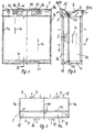
- the heat exchanger from a in a housing 1 approximately in cuboid shape arranged radiator block 2 consists of the package construction is made.
- the radiator block consists of mutually parallel Flat tubes 3, in the direction of arrows 4 and 5, respectively to be flowed through by a liquid medium and in the housing. 1 with their larger, serving as heat transfer surfaces side surfaces run parallel to the side walls 1a.
- Between the flat tubes 3 are each perpendicular to the flow directions 4 or 5 running strips 6 inserted so that between adjacent flat tubes 3 flow channels 7 (see FIGS. 5 and 6), which flows in the direction of the arrows 8 of air become.
- the flat tubes 3 is the front side in each case a collecting space 9 for Supply of a liquid medium 9 upstream, but only one Part of the inlet end faces of the flat tubes 3 covered and with a boundary wall 10 sealed in front of the end faces of the Flat tubes 3 ends.
- the entry collection space 9 is a deflection space 11 assigned on the other side of the flat tubes 3, in which the through an inlet nozzle 12 and fed in the direction of the arrow 4 flowing liquid medium is deflected and the flat tubes 3 by a Exit nozzle 13 leaves, the one the Zuwoodsammelraum 9 sibling collecting space 9a is assigned. In known Way is to make this flow in the sense of Arrows 4 to reach, a partition 14 in the middle between the collecting boxes 9 and 9a arranged.
- a this section 3b of the flat tubes associated deflection space 18 leads through the feed opening 16 in the direction of the arrows 5 fed liquid medium to the located next to the feed space 15 collecting space 15 a, from where the Medium can escape through the outlet nozzle 17 again.
- the plenums 15 and 15a have boundary walls 19 on (Fig. 4), which is sealed at the end faces the flat tubes 3 ends.
- oil for cooling a power converter introduced by the outlet pipe 13 cooled back is returned.
- water for cooling of a transformer are fed into the heat exchanger, via the outlet nozzle 17 back to the transformer is returned.
- a two-circuit radiator block is shown.
- multi-circuit cooler system So then, if three different liquid cooling media flow through the flat tubes and through the perpendicular to it flowing air to be cooled, each between adjacent Cooling circuits run a flow channel in the sense of the flow channel 21 to be arranged as a leakage channel. Also in this case is an undesired mixing of the cooling circuit liquid locked out.
Landscapes
- Engineering & Computer Science (AREA)
- Physics & Mathematics (AREA)
- Thermal Sciences (AREA)
- Mechanical Engineering (AREA)
- General Engineering & Computer Science (AREA)
- Heat-Exchange Devices With Radiators And Conduit Assemblies (AREA)
- Cooling, Air Intake And Gas Exhaust, And Fuel Tank Arrangements In Propulsion Units (AREA)
Claims (6)
- Echangeur de chaleur, notamment pour des véhicules ferroviaires, comprenant un bloc refroidisseur à deux ou plusieurs circuits qui est composé tel qu'un paquet de tubes plats (3) superposés alternativement, les canaux d'écoulement formés par les tubes plats étant traversés par des fluides liquides différents dans au moins deux segments (3a, 3b) et les espaces entre les tubes plats étant traversés par l'air, et les tubes plats (3), à la limite entre les zones d'écoulement (3a, 3b) des fluides liquides différents, étant munis d'un canal d'écoulement (21) traversant et fermé par rapport aux canaux d'écoulement voisins, qui, en tant que canal de fuite, mène du bloc refroidisseur vers l'extérieur, caractérisé en ce que le canal d'écoulement (21) servant de canal de fuite est formé par deux rails (20, 20a) introduits à distance l'un de l'autre dans les tubes plats.
- Echangeur de chaleur selon la revendication 1, caractérisé en ce que des rails de distance sont disposés de façon régulièrement répartie entre les tubes plats (3), et l'air traverse des canaux (7) situés entre les rails de distance.
- Echangeur de chaleur selon la revendication 1, caractérisé en ce que des boítiers d'alimentation et d'évacuation (9, 9a ; 15, 15a ; 11, 18) pour les fluides liquides sont limités à des zones de longueur différentes des canaux (7) traversés par l'air et munis d'ouvertures (22) vers l'environnement dans la zone du canal de fuite (21).
- Echangeur de chaleur selon la revendication 3, caractérisé en ce que les ouvertures présentent la forme de fentes (22) s'étendant sur la largueur de boítier.
- Echangeur de chaleur selon la revendication 4, caractérisé en ce que les fentes (22) sont disposées respectivement entre les arêtes de délimitation (10, 19) des boítiers d'alimentation et d'évacuation (9, 9a ; 15, 15a ; 11, 18).
- Echangeur de chaleur selon la revendication 5, caractérisé en ce que les arêtes de délimitation (10, 19) passent dans des éléments de paroi (23, 24) qui forment des évasements à partir des bouches du canal de fuite (21) vers l'extérieur.
Applications Claiming Priority (2)
| Application Number | Priority Date | Filing Date | Title |
|---|---|---|---|
| DE19921273A DE19921273A1 (de) | 1999-05-07 | 1999-05-07 | Wärmeübertrager, insbesondere für Schienenfahrzeuge |
| DE19921273 | 1999-05-07 |
Publications (2)
| Publication Number | Publication Date |
|---|---|
| EP1050732A1 EP1050732A1 (fr) | 2000-11-08 |
| EP1050732B1 true EP1050732B1 (fr) | 2005-05-11 |
Family
ID=7907430
Family Applications (1)
| Application Number | Title | Priority Date | Filing Date |
|---|---|---|---|
| EP00107998A Expired - Lifetime EP1050732B1 (fr) | 1999-05-07 | 2000-04-18 | Echangeur de chaleur, notamment pour véhicule ferroviaire |
Country Status (5)
| Country | Link |
|---|---|
| EP (1) | EP1050732B1 (fr) |
| AT (1) | ATE295522T1 (fr) |
| DE (2) | DE19921273A1 (fr) |
| DK (1) | DK1050732T3 (fr) |
| ES (1) | ES2241525T3 (fr) |
Families Citing this family (2)
| Publication number | Priority date | Publication date | Assignee | Title |
|---|---|---|---|---|
| DE10102639A1 (de) * | 2001-01-20 | 2002-07-25 | Bayerische Motoren Werke Ag | Wärmetauscher sowie Wasserkastenelement hierfür |
| DE102010042391A1 (de) * | 2010-10-13 | 2012-04-19 | Behr Gmbh & Co. Kg | Wärmeübertrager |
Family Cites Families (11)
| Publication number | Priority date | Publication date | Assignee | Title |
|---|---|---|---|---|
| GB1185469A (en) * | 1966-11-18 | 1970-03-25 | Marston Excelsior Ltd | Plate-Type Heat Exchanger. |
| FR2454075A1 (fr) * | 1979-04-13 | 1980-11-07 | Applic Thermiq Cie Indle | Perfectionnements aux echangeurs pour la production d'eau chaude sanitaire |
| DE3300523A1 (de) * | 1983-01-10 | 1984-07-12 | Funke Wärmeaustauscher Apparatebau KG, 3212 Gronau | Plattenwaermeaustauscher |
| DE3910850A1 (de) * | 1989-04-04 | 1990-10-11 | Funke Waerme Apparate Kg | Plattenwaermeaustauscher |
| US5186244A (en) * | 1992-04-08 | 1993-02-16 | General Motors Corporation | Tube design for integral radiator/condenser |
| DE4403144C3 (de) * | 1994-02-02 | 2002-05-29 | Laengerer & Reich Gmbh & Co | Plattenwärmeaustauscher |
| DE19536116B4 (de) * | 1995-09-28 | 2005-08-11 | Behr Gmbh & Co. Kg | Wärmeübertrager für ein Kraftfahrzeug |
| DE19608049A1 (de) * | 1996-03-02 | 1997-09-04 | Behr Gmbh & Co | Rohrleitung für ein Wärmeübertragersystem und diese verwendende Fahrzeugklimaanlage |
| DE19644586C2 (de) * | 1996-10-26 | 2000-10-26 | Behr Industrietech Gmbh & Co | Rippenrohrblock für einen Wärmeübertrager |
| DE19651625A1 (de) * | 1996-12-12 | 1998-06-18 | Behr Industrietech Gmbh & Co | Wärmeübertrager |
| DE19722097A1 (de) * | 1997-05-27 | 1998-12-03 | Behr Gmbh & Co | Wärmeübertrager sowie Wärmeübertrageranordnung für ein Kraftfahrzeug |
-
1999
- 1999-05-07 DE DE19921273A patent/DE19921273A1/de not_active Withdrawn
-
2000
- 2000-04-18 DK DK00107998T patent/DK1050732T3/da active
- 2000-04-18 AT AT00107998T patent/ATE295522T1/de not_active IP Right Cessation
- 2000-04-18 ES ES00107998T patent/ES2241525T3/es not_active Expired - Lifetime
- 2000-04-18 DE DE50010261T patent/DE50010261D1/de not_active Expired - Lifetime
- 2000-04-18 EP EP00107998A patent/EP1050732B1/fr not_active Expired - Lifetime
Also Published As
| Publication number | Publication date |
|---|---|
| DE19921273A1 (de) | 2000-11-09 |
| EP1050732A1 (fr) | 2000-11-08 |
| DK1050732T3 (da) | 2005-08-29 |
| ES2241525T3 (es) | 2005-11-01 |
| DE50010261D1 (de) | 2005-06-16 |
| ATE295522T1 (de) | 2005-05-15 |
Similar Documents
| Publication | Publication Date | Title |
|---|---|---|
| DE3017701C2 (de) | Plattenwärmetauscher in Stapelbauweise für mindestens drei Wärmetauschermedien | |
| DE19654362B4 (de) | Wärmeübertrageranordnung | |
| EP0789213B1 (fr) | Echangeur de chaleur pour véhicule automobile | |
| DE69911131T2 (de) | Wärmetauscher | |
| DE60109107T2 (de) | Plattenwärmetauscher | |
| DE19709601A1 (de) | Plattenwärmeübertrager | |
| DE3909996C2 (fr) | ||
| DE4403144C3 (de) | Plattenwärmeaustauscher | |
| DE4416616C2 (de) | Gehäuse | |
| DE4441503C2 (de) | Wärmetauscher, insbesondere für Kraftfahrzeuge | |
| EP0014863A1 (fr) | Echangeur de chaleur en continu pour un fluide gazeux | |
| DE69416037T2 (de) | Wärmetauscher | |
| DE2613747A1 (de) | Roehrenwaermetauscher | |
| DE2903543A1 (de) | Fluessigkeitswaermetauscher, insbesondere wasserdurchstroemter oelkuehler, vor allem fuer fahrzeuge | |
| DE69802353T2 (de) | Luftgekühlter kondensator | |
| DE3148941C2 (de) | Wassergekühlter Ölkühler für Verbrennungskraftmaschinen | |
| DE102004044861A1 (de) | Wärmetauscher für Kraftfahrzeuge | |
| EP0844454A1 (fr) | Echangeur de chaleur à contre courant | |
| EP0449124A1 (fr) | Echangeur de chaleur à espace annulaire | |
| DE19716845B4 (de) | Wärmeübertrager | |
| EP1050732A1 (fr) | Echangeur de chaleur, notamment pour véhicule ferroviaire | |
| EP1770345B1 (fr) | Réseau d'échange de chaleur et échangeur de chaleur comprenant celui-ci | |
| DE4131777A1 (de) | Fluiddurchstroemter schalldaempfer | |
| DE19757805A1 (de) | Wärmeübertrager | |
| DE19757803A1 (de) | Wärmeübertrager |
Legal Events
| Date | Code | Title | Description |
|---|---|---|---|
| PUAI | Public reference made under article 153(3) epc to a published international application that has entered the european phase |
Free format text: ORIGINAL CODE: 0009012 |
|
| AK | Designated contracting states |
Kind code of ref document: A1 Designated state(s): AT BE CH CY DE DK ES FI FR GB GR IE IT LI LU MC NL PT SE |
|
| AX | Request for extension of the european patent |
Free format text: AL;LT;LV;MK;RO;SI |
|
| 17P | Request for examination filed |
Effective date: 20001212 |
|
| AKX | Designation fees paid |
Free format text: AT BE CH CY DE DK ES FI FR GB GR IE IT LI LU MC NL PT SE |
|
| 17Q | First examination report despatched |
Effective date: 20020823 |
|
| GRAP | Despatch of communication of intention to grant a patent |
Free format text: ORIGINAL CODE: EPIDOSNIGR1 |
|
| GRAS | Grant fee paid |
Free format text: ORIGINAL CODE: EPIDOSNIGR3 |
|
| GRAA | (expected) grant |
Free format text: ORIGINAL CODE: 0009210 |
|
| RAP1 | Party data changed (applicant data changed or rights of an application transferred) |
Owner name: BEHR INDUSTRY GMBH & CO. KG |
|
| AK | Designated contracting states |
Kind code of ref document: B1 Designated state(s): AT BE CH CY DE DK ES FI FR GB GR IE IT LI LU MC NL PT SE |
|
| PG25 | Lapsed in a contracting state [announced via postgrant information from national office to epo] |
Ref country code: IE Free format text: LAPSE BECAUSE OF FAILURE TO SUBMIT A TRANSLATION OF THE DESCRIPTION OR TO PAY THE FEE WITHIN THE PRESCRIBED TIME-LIMIT Effective date: 20050511 Ref country code: NL Free format text: LAPSE BECAUSE OF FAILURE TO SUBMIT A TRANSLATION OF THE DESCRIPTION OR TO PAY THE FEE WITHIN THE PRESCRIBED TIME-LIMIT Effective date: 20050511 Ref country code: FI Free format text: LAPSE BECAUSE OF FAILURE TO SUBMIT A TRANSLATION OF THE DESCRIPTION OR TO PAY THE FEE WITHIN THE PRESCRIBED TIME-LIMIT Effective date: 20050511 |
|
| REG | Reference to a national code |
Ref country code: GB Ref legal event code: FG4D Free format text: NOT ENGLISH |
|
| REG | Reference to a national code |
Ref country code: CH Ref legal event code: EP |
|
| REG | Reference to a national code |
Ref country code: IE Ref legal event code: FG4D Free format text: LANGUAGE OF EP DOCUMENT: GERMAN |
|
| REF | Corresponds to: |
Ref document number: 50010261 Country of ref document: DE Date of ref document: 20050616 Kind code of ref document: P |
|
| PG25 | Lapsed in a contracting state [announced via postgrant information from national office to epo] |
Ref country code: SE Free format text: LAPSE BECAUSE OF FAILURE TO SUBMIT A TRANSLATION OF THE DESCRIPTION OR TO PAY THE FEE WITHIN THE PRESCRIBED TIME-LIMIT Effective date: 20050811 Ref country code: GR Free format text: LAPSE BECAUSE OF FAILURE TO SUBMIT A TRANSLATION OF THE DESCRIPTION OR TO PAY THE FEE WITHIN THE PRESCRIBED TIME-LIMIT Effective date: 20050811 |
|
| REG | Reference to a national code |
Ref country code: DK Ref legal event code: T3 |
|
| GBT | Gb: translation of ep patent filed (gb section 77(6)(a)/1977) |
Effective date: 20050907 |
|
| PG25 | Lapsed in a contracting state [announced via postgrant information from national office to epo] |
Ref country code: PT Free format text: LAPSE BECAUSE OF FAILURE TO SUBMIT A TRANSLATION OF THE DESCRIPTION OR TO PAY THE FEE WITHIN THE PRESCRIBED TIME-LIMIT Effective date: 20051019 |
|
| NLV1 | Nl: lapsed or annulled due to failure to fulfill the requirements of art. 29p and 29m of the patents act | ||
| REG | Reference to a national code |
Ref country code: ES Ref legal event code: FG2A Ref document number: 2241525 Country of ref document: ES Kind code of ref document: T3 |
|
| REG | Reference to a national code |
Ref country code: IE Ref legal event code: FD4D |
|
| PLBE | No opposition filed within time limit |
Free format text: ORIGINAL CODE: 0009261 |
|
| STAA | Information on the status of an ep patent application or granted ep patent |
Free format text: STATUS: NO OPPOSITION FILED WITHIN TIME LIMIT |
|
| ET | Fr: translation filed | ||
| PG25 | Lapsed in a contracting state [announced via postgrant information from national office to epo] |
Ref country code: MC Free format text: LAPSE BECAUSE OF NON-PAYMENT OF DUE FEES Effective date: 20060430 Ref country code: LI Free format text: LAPSE BECAUSE OF NON-PAYMENT OF DUE FEES Effective date: 20060430 Ref country code: CH Free format text: LAPSE BECAUSE OF NON-PAYMENT OF DUE FEES Effective date: 20060430 Ref country code: BE Free format text: LAPSE BECAUSE OF NON-PAYMENT OF DUE FEES Effective date: 20060430 |
|
| 26N | No opposition filed |
Effective date: 20060214 |
|
| REG | Reference to a national code |
Ref country code: CH Ref legal event code: PL |
|
| BERE | Be: lapsed |
Owner name: BEHR INDUSTRY G.M.B.H. & CO. KG Effective date: 20060430 |
|
| PG25 | Lapsed in a contracting state [announced via postgrant information from national office to epo] |
Ref country code: LU Free format text: LAPSE BECAUSE OF NON-PAYMENT OF DUE FEES Effective date: 20060418 |
|
| PG25 | Lapsed in a contracting state [announced via postgrant information from national office to epo] |
Ref country code: CY Free format text: LAPSE BECAUSE OF FAILURE TO SUBMIT A TRANSLATION OF THE DESCRIPTION OR TO PAY THE FEE WITHIN THE PRESCRIBED TIME-LIMIT Effective date: 20050511 |
|
| PGFP | Annual fee paid to national office [announced via postgrant information from national office to epo] |
Ref country code: ES Payment date: 20100427 Year of fee payment: 11 Ref country code: DK Payment date: 20100413 Year of fee payment: 11 Ref country code: FR Payment date: 20100506 Year of fee payment: 11 |
|
| PGFP | Annual fee paid to national office [announced via postgrant information from national office to epo] |
Ref country code: DE Payment date: 20100424 Year of fee payment: 11 Ref country code: IT Payment date: 20100427 Year of fee payment: 11 Ref country code: AT Payment date: 20100415 Year of fee payment: 11 |
|
| PGFP | Annual fee paid to national office [announced via postgrant information from national office to epo] |
Ref country code: GB Payment date: 20100420 Year of fee payment: 11 |
|
| REG | Reference to a national code |
Ref country code: FR Ref legal event code: RT |
|
| REG | Reference to a national code |
Ref country code: DK Ref legal event code: EAP |
|
| PG25 | Lapsed in a contracting state [announced via postgrant information from national office to epo] |
Ref country code: DE Free format text: LAPSE BECAUSE OF THE APPLICANT RENOUNCES Effective date: 20101126 |
|
| REG | Reference to a national code |
Ref country code: GB Ref legal event code: S29 Free format text: OFFER ACCEPTED; APPLICATION FILED ON 26 NOVEMBER 2010 |
|
| REG | Reference to a national code |
Ref country code: ES Ref legal event code: FD2A Effective date: 20110310 |
|
| PG25 | Lapsed in a contracting state [announced via postgrant information from national office to epo] |
Ref country code: AT Free format text: LAPSE BECAUSE OF THE APPLICANT RENOUNCES Effective date: 20101127 |
|
| PG25 | Lapsed in a contracting state [announced via postgrant information from national office to epo] |
Ref country code: ES Free format text: LAPSE BECAUSE OF NON-PAYMENT OF DUE FEES Effective date: 20110304 Ref country code: GB Free format text: LAPSE BECAUSE OF THE APPLICANT RENOUNCES Effective date: 20110309 |
|
| PG25 | Lapsed in a contracting state [announced via postgrant information from national office to epo] |
Ref country code: DK Free format text: LAPSE BECAUSE OF THE APPLICANT RENOUNCES Effective date: 20101201 |
|
| REG | Reference to a national code |
Ref country code: FR Ref legal event code: ST Effective date: 20111230 |
|
| PG25 | Lapsed in a contracting state [announced via postgrant information from national office to epo] |
Ref country code: FR Free format text: LAPSE BECAUSE OF NON-PAYMENT OF DUE FEES Effective date: 20110502 |
|
| PG25 | Lapsed in a contracting state [announced via postgrant information from national office to epo] |
Ref country code: IT Free format text: LAPSE BECAUSE OF NON-PAYMENT OF DUE FEES Effective date: 20110418 |