EP1050925B1 - Mehrfach-primärstrahler, abwärtsumsetzer und mehrkeulen-antenne - Google Patents
Mehrfach-primärstrahler, abwärtsumsetzer und mehrkeulen-antenne Download PDFInfo
- Publication number
- EP1050925B1 EP1050925B1 EP98936690A EP98936690A EP1050925B1 EP 1050925 B1 EP1050925 B1 EP 1050925B1 EP 98936690 A EP98936690 A EP 98936690A EP 98936690 A EP98936690 A EP 98936690A EP 1050925 B1 EP1050925 B1 EP 1050925B1
- Authority
- EP
- European Patent Office
- Prior art keywords
- converter
- block
- aperture
- angle
- primary radiator
- Prior art date
- Legal status (The legal status is an assumption and is not a legal conclusion. Google has not performed a legal analysis and makes no representation as to the accuracy of the status listed.)
- Expired - Lifetime
Links
- 230000010287 polarization Effects 0.000 claims abstract description 34
- 238000006243 chemical reaction Methods 0.000 claims abstract description 13
- 230000005855 radiation Effects 0.000 claims description 18
- 230000003321 amplification Effects 0.000 claims description 4
- 230000008878 coupling Effects 0.000 claims description 4
- 238000010168 coupling process Methods 0.000 claims description 4
- 238000005859 coupling reaction Methods 0.000 claims description 4
- 238000003199 nucleic acid amplification method Methods 0.000 claims description 4
- 238000005192 partition Methods 0.000 claims description 4
- 230000002093 peripheral effect Effects 0.000 claims 6
- 230000001105 regulatory effect Effects 0.000 abstract 1
- 238000010276 construction Methods 0.000 description 5
- 238000000034 method Methods 0.000 description 5
- 238000004891 communication Methods 0.000 description 3
- 238000001746 injection moulding Methods 0.000 description 3
- 230000005574 cross-species transmission Effects 0.000 description 2
- 230000007423 decrease Effects 0.000 description 2
- 238000009434 installation Methods 0.000 description 2
- 238000004519 manufacturing process Methods 0.000 description 2
- 241001442234 Cosa Species 0.000 description 1
- 239000000470 constituent Substances 0.000 description 1
- 230000001419 dependent effect Effects 0.000 description 1
- 230000006866 deterioration Effects 0.000 description 1
- 238000002955 isolation Methods 0.000 description 1
- 230000000149 penetrating effect Effects 0.000 description 1
- 239000000523 sample Substances 0.000 description 1
- 238000000926 separation method Methods 0.000 description 1
Images










Classifications
-
- H—ELECTRICITY
- H01—ELECTRIC ELEMENTS
- H01Q—ANTENNAS, i.e. RADIO AERIALS
- H01Q25/00—Antennas or antenna systems providing at least two radiating patterns
-
- H—ELECTRICITY
- H01—ELECTRIC ELEMENTS
- H01Q—ANTENNAS, i.e. RADIO AERIALS
- H01Q1/00—Details of, or arrangements associated with, antennas
- H01Q1/12—Supports; Mounting means
- H01Q1/22—Supports; Mounting means by structural association with other equipment or articles
- H01Q1/24—Supports; Mounting means by structural association with other equipment or articles with receiving set
- H01Q1/247—Supports; Mounting means by structural association with other equipment or articles with receiving set with frequency mixer, e.g. for direct satellite reception or Doppler radar
-
- H—ELECTRICITY
- H01—ELECTRIC ELEMENTS
- H01Q—ANTENNAS, i.e. RADIO AERIALS
- H01Q13/00—Waveguide horns or mouths; Slot antennas; Leaky-waveguide antennas; Equivalent structures causing radiation along the transmission path of a guided wave
- H01Q13/06—Waveguide mouths
- H01Q13/065—Waveguide mouths provided with a flange or a choke
-
- H—ELECTRICITY
- H01—ELECTRIC ELEMENTS
- H01Q—ANTENNAS, i.e. RADIO AERIALS
- H01Q19/00—Combinations of primary active antenna elements and units with secondary devices, e.g. with quasi-optical devices, for giving the antenna a desired directional characteristic
- H01Q19/10—Combinations of primary active antenna elements and units with secondary devices, e.g. with quasi-optical devices, for giving the antenna a desired directional characteristic using reflecting surfaces
- H01Q19/12—Combinations of primary active antenna elements and units with secondary devices, e.g. with quasi-optical devices, for giving the antenna a desired directional characteristic using reflecting surfaces wherein the surfaces are concave
-
- H—ELECTRICITY
- H01—ELECTRIC ELEMENTS
- H01Q—ANTENNAS, i.e. RADIO AERIALS
- H01Q19/00—Combinations of primary active antenna elements and units with secondary devices, e.g. with quasi-optical devices, for giving the antenna a desired directional characteristic
- H01Q19/10—Combinations of primary active antenna elements and units with secondary devices, e.g. with quasi-optical devices, for giving the antenna a desired directional characteristic using reflecting surfaces
- H01Q19/12—Combinations of primary active antenna elements and units with secondary devices, e.g. with quasi-optical devices, for giving the antenna a desired directional characteristic using reflecting surfaces wherein the surfaces are concave
- H01Q19/17—Combinations of primary active antenna elements and units with secondary devices, e.g. with quasi-optical devices, for giving the antenna a desired directional characteristic using reflecting surfaces wherein the surfaces are concave the primary radiating source comprising two or more radiating elements
-
- H—ELECTRICITY
- H01—ELECTRIC ELEMENTS
- H01Q—ANTENNAS, i.e. RADIO AERIALS
- H01Q19/00—Combinations of primary active antenna elements and units with secondary devices, e.g. with quasi-optical devices, for giving the antenna a desired directional characteristic
- H01Q19/10—Combinations of primary active antenna elements and units with secondary devices, e.g. with quasi-optical devices, for giving the antenna a desired directional characteristic using reflecting surfaces
- H01Q19/12—Combinations of primary active antenna elements and units with secondary devices, e.g. with quasi-optical devices, for giving the antenna a desired directional characteristic using reflecting surfaces wherein the surfaces are concave
- H01Q19/17—Combinations of primary active antenna elements and units with secondary devices, e.g. with quasi-optical devices, for giving the antenna a desired directional characteristic using reflecting surfaces wherein the surfaces are concave the primary radiating source comprising two or more radiating elements
- H01Q19/175—Combinations of primary active antenna elements and units with secondary devices, e.g. with quasi-optical devices, for giving the antenna a desired directional characteristic using reflecting surfaces wherein the surfaces are concave the primary radiating source comprising two or more radiating elements arrayed along the focal line of a cylindrical focusing surface
-
- H—ELECTRICITY
- H01—ELECTRIC ELEMENTS
- H01Q—ANTENNAS, i.e. RADIO AERIALS
- H01Q3/00—Arrangements for changing or varying the orientation or the shape of the directional pattern of the waves radiated from an antenna or antenna system
- H01Q3/12—Arrangements for changing or varying the orientation or the shape of the directional pattern of the waves radiated from an antenna or antenna system using mechanical relative movement between primary active elements and secondary devices of antennas or antenna systems
- H01Q3/16—Arrangements for changing or varying the orientation or the shape of the directional pattern of the waves radiated from an antenna or antenna system using mechanical relative movement between primary active elements and secondary devices of antennas or antenna systems for varying relative position of primary active element and a reflecting device
- H01Q3/18—Arrangements for changing or varying the orientation or the shape of the directional pattern of the waves radiated from an antenna or antenna system using mechanical relative movement between primary active elements and secondary devices of antennas or antenna systems for varying relative position of primary active element and a reflecting device wherein the primary active element is movable and the reflecting device is fixed
-
- H—ELECTRICITY
- H01—ELECTRIC ELEMENTS
- H01Q—ANTENNAS, i.e. RADIO AERIALS
- H01Q5/00—Arrangements for simultaneous operation of antennas on two or more different wavebands, e.g. dual-band or multi-band arrangements
- H01Q5/40—Imbricated or interleaved structures; Combined or electromagnetically coupled arrangements, e.g. comprising two or more non-connected fed radiating elements
- H01Q5/45—Imbricated or interleaved structures; Combined or electromagnetically coupled arrangements, e.g. comprising two or more non-connected fed radiating elements using two or more feeds in association with a common reflecting, diffracting or refracting device
Definitions
- the present invention relates to a parabolic antenna for use in satellite broadcasting or satellite communication and more particularly, to a primary radiator and a block-down-converter which constitute the parabolic antenna.
- parabolic antennas which receive radio waves from a plurality of stationary satellites by a single reflector are referred to as “dual-beam antennas” or “multi-beam antennas” and are mainly adapted to receive radio waves from two satellites located on a stationary orbit with a difference of longitude of 8 degrees.
- a dual-beam antenna 100 includes primary radiators 102 and 103 constituting a double primary radiator and a reflector 101.
- the primary radiators 102 and 103 and the reflector 101 are coupled with each other by a support arm 104 so as to have a predetermined positional relationship.
- Radio waves from first and second satellites are reflected by the reflector 101 so as to be, respectively, received by the primary radiators 102 and 103.
- axes of the primary radiators are disposed so as to extend horizontally at the time of reception.
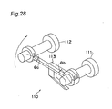
- Fig. 28 is a perspective view indicative of one example of adjustment of the polarization angle. As shown in Fig. 28 , the adjustment is performed by rotating an arm 113 through an angle ⁇ b about an axis of a fixed primary radiator 111 and further, rotating a primary radiator 112 through an angle ⁇ a about its own axis.
- Fig. 29 shows relation between antenna diameter D and primary radiator spacing L in the case where difference of longitude between two satellites on a stationary orbit is 8 degrees and 4 degrees.
- the reflector diameter D and the primary radiator spacing L are substantially proportional to each other and an optimum value of the primary radiator spacing at the time the difference of longitude is 4 degrees is smaller than that at the time the difference of longitude is 8 degrees.
- Fig. 30 shows relation between aperture diameter d of a primary radiator and antenna efficiency ⁇ in a single-beam antenna.
- the antenna efficiency ⁇ reaches a maximum ⁇ max , as follows. If the aperture diameter is small, radiation range over the reflector increases and thus, energy of the reflector spills from the reflector, namely, spill-over happens. On the other hand, if the aperture diameter is large excessively, radiation range decreases and thus, an edge portion of the reflector does not work.
- the spacing Lo should be larger than d opt .
- the spacing L decreases to Ls. If the spacing Ls is smaller than d opt , the aperture diameter d necessarily becomes smaller than d opt yielding the maximum efficiency ⁇ max so that the antenna efficiency ⁇ drops markedly to ⁇ o as shown in Fig. 30 and thus, it becomes difficult to obtain desired reception performance.
- DE 38 29 370 A1 discloses a reflector aerial radiating system where two radiators are mechanically connected one another to generate two closely adjacent radiation lobes.
- the radiators consist of actually symmetrical horn radiators which partially penetrate each other.
- Mutually penetrating grooves in a contact zone between the radiators ensure sufficient decoupling between the radiation patterns.
- EP 0 350 324 A2 discloses a waveguide coupling arrangement where a capacitively coupled printed patch is provided as a high-efficiency device to couple orthogonally polarised energy between a stripline and a waveguide. Coupling between the stripline and the patch is achieved by the stripline terminating in a narrow strip probe, the end of which lies close to, but not in contact with, an edge of the patch.
- a double primary radiator of the present invention has a construction in which by using a small-diameter parabolic reflector having an effective diameter of, for example, 45 cm, two primary radiators are integrally joined with each other so as to receive radio waves from two satellites having a difference of longitude of, for example, 4 degrees.
- the double primary radiator of the present invention since apertures of the primary radiators are arranged to face each other inwardly, it is possible to compensate for reduction of radiation area due to defocus caused in the case where a dual-beam antenna is arranged such that a central point of a joint part of the double primary radiators is located in the vicinity of a focal point of the reflector.
- a block-down-converter of the present invention can be rotated as a whole about a perpendicular radiation axis, tilt angle of the two radiators can be adjusted relative to polarization angle at a time.
- an initial shift angle for adjusting polarization angle is set to that of a point located substantially at a center of a longitudinal range of a receiving area, adjustment of the initial shift angle can be substantially optimized throughout the receiving area. Therefore, since it is not necessary to adjust the initial shift angle for each receiving point, the block-down-converters can be mass produced.
- the block-down-converter of the present invention has a construction in which a double primary radiator and a housing containing a conversion circuit for performing amplification and frequency conversion of received radio waves are integrally molded, the block-down-converter can be produced by a simple process such as injection molding employing a die, thereby resulting in its production cost.
- Figs. 1 and 2 are a front elevational view and a sectional view of a double primary radiator according to a first embodiment of the present invention, respectively.
- a double primary radiator 10a is constituted by primary radiators 1 and 2.
- the primary radiator 1 is constituted by a feed horn 6 and a circular waveguide 3, while the primary radiator 2 is constituted by a feed horn 7 and a circular waveguide 4.
- the feed horns 6 and 7 are each provided in a tapered shape at an outer periphery of an aperture of the primary radiator and are coupled with each other at a joint part 5 so as to be excised partially.
- an end face of the waveguide adjacent to the aperture is referred to as an "aperture face" of the primary radiator.
- a middle point of a segment connecting centers of the two apertures, namely, a central point in the joint part is referred to as a "central point of the joint part”
- a perpendicular bisector 8 of the segment connecting the centers of the two apertures is referred to as a "central line of the joint part”.
- an aperture face of the primary radiator 1 and an aperture face of the primary radiator 2 are formed in an identical plane as shown in Fig. 2 .
- a straight line 9 passing through the central point of the joint part and running parallel with axes of the two primary radiators is defined as a "perpendicular radiation axis" of the double primary radiator 10a.
- Figs. 3 and 4 are a front elevational view and a sectional view of a double primary radiator according to a second embodiment of the present invention, respectively.
- a double primary radiator 10b of this embodiment has feed horns and circular waveguides.
- the double primary radiator 10b further includes a corrugate portion 13 formed by an annular groove having a predetermined width and a predetermined depth.
- the corrugate portions 13 are likewise coupled with each other in the vicinity of a joint part for joining the feed horns 11 and 12. The corrugate portions lessen the influence of excision of the feed horns at the joint part and thus, can improve performances such as antenna efficiency, antenna directivity, beam separation degree corresponding to angle for viewing two satellites, etc.
- a double primary radiator 10c shown in a front elevational view of Fig. 5 and a sectional view of Fig. 6 has feed horns and circular waveguides in the same manner as the double primary radiator 10b. However, in this embodiment, feed horns 18 and 19 are not coupled with each other and only corrugate portions 17 are coupled with each other at a joint part 16.
- the double primary radiator having such an arrangement is used for receiving radio waves from two satellites located with a difference of longitude of 8 degrees.
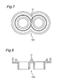
- Figs. 7 and 8 are a front elevational view and a sectional view of a double primary reflector 10d, respectively. As shown in Figs. 7 and 8 , two feed horns may come into contact with each other at a joint part 21 according to diameter of a reflector.
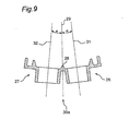
- Fig. 9 is a sectional view of a double primary radiator 30a according to a third embodiment of the present invention.
- the double primary radiator 30a is constituted by constituent elements similar to those of the double primary radiator 10b of the second embodiment.
- the double primary radiator 30a is different from the double primary radiator 10b in that a waveguide axis 31 passing through a center of an aperture face of a primary radiator 26 perpendicularly to this aperture face and a waveguide axis 32 passing through a center of an aperture face of a primary radiator 27 perpendicularly to this aperture face form a predetermined angle as shown in Fig. 9 .
- the waveguide axes 31 and 32 have a point of intersection (not shown).
- a straight line 29 connecting this point of intersection and a central point of a joint part acts as a perpendicular radiation axis of the double primary radiator 30a.
- Each of an angle formed between the waveguide axis 31 and the perpendicular radiation axis 29 and an angle formed between the waveguide axis 32 and the perpendicular radiation axis 29 is ⁇ .
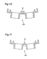
- two primary radiators are formed such that two waveguide axes have a point of intersection in the double primary radiator 10c and only corrugate portions are coupled with each other at a joint part 33.
- two primary radiators are formed such that two waveguide axes have a point of intersection in the double primary radiator 10d and feed horns are coupled with each other at a joint part 34.
- Figs. 12 and 13 are a front elevational view and a sectional view of a double primary radiator according to a fourth embodiment of the present invention, respectively.
- feed horns 41 and 42, corrugate portions 46 and a joint part 45 in a double primary radiator 50a have shapes similar to those of the double primary radiator 30a of Fig. 9 .
- the double primary radiator 50a is different from the double primary radiator 30a in that straight lines 47 and 48 perpendicular to respective aperture faces have a point of intersection in place of waveguide axes 43 and 44 parallel to each other.
- a construction similar to that of this embodiment may also be applied to the waveguides of the double primary radiators shown in Figs. 10 and 11 .
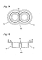
- Figs. 14 and 15 are a front elevational view and a sectional view of a modified double primary radiator 50b of this embodiment, respectively.
- a partition member 53 having a predetermined thickness and a predetermined height is provided at a joint part so as to compensate for excised portions of the two feed horns at the joint part 45 of the double primary radiator 50a.
- the partition member 53 also has a tapered shape in the same manner as feed horns.
- the partition portion 53 compensates for the excised portions of the feed horns, it is possible to improve isolation performance in radio waves from two satellites. As a result, it is possible to prevent drop of antenna directivity at the time of incidence of radio wave subjected to horizontal polarization.
- the double primary radiator has two parallel waveguides and therefore, can be obtained by a simple process such as injection molding employing a die.
- All the double primary radiators of the above embodiments are arranged to receive radio waves from two satellites.
- a multi-primary radiator is employed in which primary radiators identical, in number, with satellites are coupled with one another such that centers of their apertures are arranged linearly, it is possible to receive radio waves from three or more satellites.
- Fig. 16 is a perspective view showing an arrangement of a block-down-converter including the above double primary radiator and a dual-beam antenna.
- a dual-beam antenna 70 is constituted by a parabolic reflector 61, a support mast 62, a support arm 63 and a block-down converter 80. Radio waves from satellites 66 and 67 are reflected by the reflector 61 so as to be received by the block-down-converter 80. Meanwhile, in coordinate axes shown in Fig. 16 , the Y-axis represents a vertical direction, while the X-axis and the Z-axis represent lateral and longitudinal directions of the dual-beam antenna 70 on the surface of the earth, respectively.
- the block-down-converter 80 is schematically illustrated in Fig. 17 .
- the block-down-converter receives radio waves from satellites by the double primary radiator and performs amplification and frequency conversion of the received radio waves.
- the block-down-converter 80 is constituted by a double primary radiator 72 having an arrangement identical with that of the double primary radiator 50b, a housing 73 containing a conversion circuit for performing amplification and frequency conversion, an F-type connector 74 acting as an output terminal of the block-down-converter 80 and a holding member 64 which is attached to a distal end of the support arm 63 so as to fix the double primary radiator 72 to the support arm 63.
- the double primary radiator 72 and the housing 73 are integrally molded and therefore, can be produced by a simple process such as injection molding employing a die, thus resulting in reduction of the production cost.
- Fig. 18 is a front elevational view of the block-down-converter 80.
- the construction of the holding member 64 enables the support arm 63 to be freely rotated about a central point 71 of a joint part, more specifically, a perpendicular radiation axis passing through the central point 71 of the joint part.
- An angle ⁇ formed between a central line 88 of the joint part and the support arm 63 denotes an angle of inclination of the block-down-converter 80 as shown in Fig. 16 and is referred to as a "tilt angle" of the block-down-converter, hereinafter.
- the central point 71 of the joint part namely, a center of an aperture face of the double primary radiator 72 is disposed in the vicinity of a focal point of the reflector 61.
- the double primary radiator 72 has a construction in which apertures of two primary radiators face each other inwardly, so that reduction of radiation area by the defocus is compensated for.
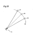
- Figs. 19 and 20 are views showing in which directions the block-down-converter 80 and the dual-beam antenna 70 are installed relative to the satellites.
- the block-down-converter 80 is installed such that the aperture of the double primary radiator 72 is directed towards the reflector 61 (not shown).
- ⁇ 1 and ⁇ 2 denote polarization angles of radio waves from the satellites 66 and 67 located on a stationary orbit 69, respectively.
- the reflector 61 is directed towards an imaginary satellite 68.
- the imaginary satellite 68 for transmitting radio waves having a polarization angle ⁇ 0 is supposed to be located on the stationary orbit 69. Since a radius of the stationary orbit of the satellites is far larger than the radius of the earth, more specifically, the equator, the imaginary polarization angle ⁇ 0 is nearly equal to a mean of ⁇ 1 and ⁇ 2, namely, an angle formed between a straight line connecting the satellites 66 and 67 and the X-axis.
- the block-down-converter 80 is installed such that the tilt angle ⁇ becomes equal to the imaginary polarization angle ⁇ 0.
- Fig. 21 is a front elevational view of a block-down-converter 80a having the tilt angle ⁇ in the same manner as in Figs. 18 and 19 .
- Fig. 21 illustrates state of feeding elements 81a, 81b, 82a and 82b formed on the conversion circuit in the housing 73 located at an output side of the circular waveguides. These four feeding elements are each formed by a microstrip line having a predetermined length and a predetermined width.
- the feeding elements 81a and 82a are formed on a straight line 89 connecting centers of the two apertures, while the feeding elements 81b and 82b are, respectively, formed on straight lines 86 and 87 passing through the centers of the two apertures perpendicularly to the central line 89 of the apertures.
- the feeding elements 81a and 81b extend orthogonally to each other, while the feeding elements 82a and 82b extend orthogonally to each other.
- the four feeding elements as a whole are formed symmetrically with respect to a central line 88 of the joint part.
- the block-down-converter 80a can be rotated about the perpendicular radiation axis of the double primary radiator and thus, the tilt angle can be adjusted simply.
- a measure of reducing the tilt angle ⁇ for effecting adjustment of the polarization angle at a receiving area may be preliminarily taken.
- a method is employed in which a predetermined polarization angle called a "slant angle" is preliminarily added, as an offset, to radio waves to be transmitted.
- an imaginary polarization angle is calculated by adding the slant angle to the polarization angle ⁇ 1 or ⁇ 2.
- each pair of the feeding elements should include at least a feeding element for vertical polarization and a feeding element for horizontal polarization and may include three or more feeding elements.
- Fig. 22 is a graph showing relation between tilt angle ⁇ and antenna gain G.
- antenna gain G drops strikingly when the tilt angle ⁇ is excessively large.
- the tilt angle ⁇ is set to 0 degree but instead, two pairs of feeding elements 81c and 81d and feeding elements 82c and 82d are formed at such positions as to be rotated through the angle ⁇ about centers of respective apertures as in a block-down-converter 80b shown in Fig. 23 .
- the polarization angle can be adjusted without incurring deterioration of antenna gain in this embodiment.
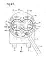
- Fig. 24 is a front elevational view of a block-down-converter 80c.
- a pair of feeding elements 81e and 81f are formed orthogonally to each other so as to be rotated counterclockwise through an initial tilt angle ⁇ 2 relative to the straight line 86, while a pair of feeding elements 82e and 82f are formed orthogonally to each other so as to be rotated clockwise through an initial shift angle ⁇ 1 relative to the straight line 87.
- these initial shift angles are determined based on a point located at a center of a longitudinal range of an area capable of receiving radio waves or a target receiving area, for example, "Shizuoka" in the case of Japan.
- ⁇ 1 and ⁇ 2 are equal to each other.
- the initial shift angles ⁇ 1 and ⁇ 2 amount to angles obtained by adding the slant angle thereto.
- Fig. 25 is a graph showing polarization adjustment error, in which the initial shift angles ⁇ 1 and ⁇ 2 are set to optimum values in Japan on the supposition that the satellites 66 and 67 are the JCSAT-3 (128° of east longitude) and the JCSAT-4 (124° of east longitude), respectively.
- the initial shift angle for adjusting the polarization angle is set to that of the point located at the center of the longitudinal range of the receiving area, adjustment of the initial shift angle can be substantially optimized in the whole receiving area. Therefore, since it is not necessary to adjust the initial shift angle at each receiving area, the block-down-converter can be mass produced.
- the block-down-converter 80c can be rotated about the perpendicular radiation axis of the double primary radiator, the tilt angle can be adjusted simply.
- Fig. 26 is a sectional view of a block-down-converter 98.
- the block-down-converter 98 is constituted by a double primary radiator 97 having apertures similar to those of the double primary radiator 30a and a printed board 96 on which a conversion circuit is formed.
- a feeding element 95 is formed on the printed board 96 and the printed board 96 is mounted on an output side of the double primary radiator 97.
- the double primary radiator 97 is different from the double primary radiator 30a in that no waveguide is provided substantially.
- a straight line 93 is a perpendicular for an aperture face.
- the aperture of the double primary radiator 97 is formed such that the straight line 93 and a perpendicular radiation axis 94 form an angle ⁇ .
- the aperture face and the printed board 96 form the angle ⁇ .
- the printed board 96 is mounted orthogonally to the perpendicular radiation axis 94.
- This embodiment is characterized in that a length of the feeding element 95 assumes (L/cosa) obtained by projecting onto the printed board along the straight line 93 a length L of a feeding element which might be formed in parallel with the aperture face.
- the block-down-converter can be made more compact.
- the parabolic antenna capable of receiving vertical polarized waves and horizontal polarized waves simultaneously can be made compact and light by maintaining antenna efficiency.
- a high-performance parabolic antenna for general home use which includes a small-diameter reflector having an effective diameter of, for example, 45 cm. If this parabolic antenna is used in, for example, Japan, it is possible to receive radio waves from the JCSAT-3 (128° of east longitude) and the JCSAT-4 (124° of east longitude).
Landscapes
- Physics & Mathematics (AREA)
- Electromagnetism (AREA)
- Engineering & Computer Science (AREA)
- Radar, Positioning & Navigation (AREA)
- Remote Sensing (AREA)
- Aerials With Secondary Devices (AREA)
- Variable-Direction Aerials And Aerial Arrays (AREA)
Claims (19)
- Block-Abwärtsumsetzer (80, 80a-c) zum Empfangen von Radiowellen von wenigstens zwei Satelliten (66, 67), der aufweist:einen ersten Primär-Radiator (1), der einen ersten peripheren Abschnitt aufweist, der eine erste Öffnung definiert und einen ersten Ausschnittsbereich aufweist,einen zweiten Primär-Radiator (2), der einen zweiten peripheren Bereich aufweist, der eine zweite Öffnung definiert und einen zweiten Ausschnittsbereich aufweist, wobei der erste Ausschnittsbereich und der zweite Ausschnittsbereich miteinander verbunden sind, um ein Verbindungsteil (5, 16, 21, 28, 33, 34, 45, 53) zu bilden, in dem der erste und der zweite Ausschnittsbereich miteinander verbunden sind,gekennzeichnet dadurch, dass er ferner aufweist:ein einzelnes Gehäuse (73) mit einer einzelnen Umsetzungsschaltung, die wenigstens ein Zuführelement (81a-f, 82a-f, 95) aufweist, wobei die einzelne Umsetzungsschaltung zum Empfangen von wenigstens zwei Radiowellen und zum Durchführen von Verstärkung und Frequenzumsetzung der empfangenen Radiowellen ausgestaltet ist.
- Block-Abwärtsumsetzer (80, 80a-c) nach Anspruch 1, wobei der erste periphere Bereich ein erstes Feedhorn (6, 11, 41) und der zweite periphere Bereich ein zweites Feedhorn (7, 12, 42) umfassen.
- Block-Abwärtsumsetzer (80, 80a-c) nach Anspruch 2, wobei der erste periphere Bereich einen ersten Nutbereich (13, 46) derart aufweist, dass das erste Feedhorn (11, 41) zwischen dem ersten Nutbereich (13, 46) und der ersten Öffnung positioniert ist, und der zweite periphere Bereich einen zweiten Nutbereich (13, 46) derart aufweist, dass das zweite Feedhorn (12, 42) zwischen dem zweiten Nutbereich (13, 46) und der zweiten Öffnung positioniert ist.
- Block-Abwärtsumsetzer (80, 80a-c) nach Anspruch 3, wobei der erste Nutbereich (13, 46) und der zweite Nutbereich (13, 46) miteinander an dem Verbindungsteil (45) verbunden sind.
- Block-Abwärtsumsetzer (80, 80a-c) nach Anspruch 2, wobei das erste Feedhorn und das zweite Feedhorn miteinander an dem Verbindungsteil (53) verbunden sind, ferner mit einem Trennungselement (53) an dem Verbindungsteil.
- Block-Abwärtsumsetzer (80, 80a-c) nach Anspruch 1, wobei die erste Öffnung eine erste Öffnungsfläche und die zweite Öffnung eine zweite Öffnungsfläche aufweisen, so dass eine erste Achse (31, 47), die durch eine Mitte der ersten Öffnung senkrecht zu der ersten Öffnungsfläche verläuft, eine zweite Achse (32, 48) schneidet, die durch eine Mitte der zweiten Öffnung senkrecht zu der zweiten Öffnungsfläche verläuft.
- Block-Abwärtsumsetzer (80, 80a-c) nach Anspruch 1, wobei der erste primäre Radiator (1) einen ersten Wellenleiter (3) mit einer ersten Wellenleiterachse (43) aufweist, und der zweite primäre Radiator (2) einen zweiten Wellenleiter (4) mit einer zweiten Wellenleiterachse (44) aufweist, wobei die erste Wellenleiterachse (43) parallel zu der zweiten Wellenleiterachse (44) ist.
- Block-Abwärtsumsetzer (80, 80a-c) nach Anspruch 1, wobei die erste Öffnung eine erste Öffnungsfläche und die zweite eine zweite Öffnungsfläche aufweisen, und das wenigstens eine Zuführelement (95) einen Winkel (α) einen Winkel (α) mit der ersten Öffnungsfläche oder der zweiten Öffnungsfläche bildet, so dass eine Länge (L/cosa) des wenigstens einen Zuführelements durch projizieren einer Länge erhalten wird, die parallel zu der ersten Öffnungsfläche oder der zweiten Öffnungsfläche ist, auf die Umsetzungsschaltung entlang einer Richtung, die senkrecht zu der ersten Öffnungsfläche oder der zweiten Öffnungsfläche ist.
- Block-Abwärtsumsetzer (80, 80a-c) nach Anspruch 1, wobei das wenigstens eine Zuführelement wenigstens zwei Zuführelemente (81a-f, 82a-f) für jeden von dem ersten primären Radiator und dem zweiten primären Radiator umfasst, wobei zwei der wenigstens zwei Zuführelemente (81a-f, 82a-f) einen rechten Winkel miteinander einschließen.
- Block-Abwärtsumsetzer (80, 80a-c) nach Anspruch 9, wobei das Verbindungsteil eine zentrale Achse (88) aufweist und wenigstens eins der wenigstens zwei Zuführelemente (81a-f, 82a-f) einen vorbestimmten Winkel (θ) mit der zentralen Achse (88) des Verbindungsteils bildet.
- Block-Abwärtsumsetzer (80, 80a-c) nach Anspruch 10, wobei der vorbestimmte Winkel (θ) im Wesentlichen gleich zu einem imaginären Polarisierungswinkel (Φ0) an einem Punkt eines vorbestimmten Längengrads ist.
- Block-Abwärtsumsetzer (80, 80a-c) nach Anspruch 11, wobei der vorbestimmte Längengrad im Wesentlichen an einer Mitte eines vorbestimmten Längengradbereichs angeordnet ist.
- Block-Abwärtsumsetzer (80, 80a-c) nach Anspruch 11, wobei der vorbestimmte Winkel ein Winkel ist, der unter Verwendung eines Blickwinkels der Radiowellen berechnet ist.
- Block-Abwärtsumsetzer (80, 80a-c) nach Anspruch 10, wobei der vorbestimmte Winkel (θ) im Wesentlichen gleich zu einer Differenz an einem Punkt eines vorbestimmten Längengrads zwischen einem imaginären Polarisierungswinkel und einem Polarisierungswinkel von Radiowellen ist, die von einem der wenigstens zwei Satelliten ausgestrahlt werden.
- Block-Abwärtsumsetzer (80, 80a-c) nach Anspruch 14, wobei der vorbestimmte Längengrad im Wesentlichen an einer Mitte eines vorbestimmten Längengradbereichs angeordnet ist.
- Block-Abwärtsumsetzer (80, 80a-c) nach Anspruch 14, wobei der vorbestimmte Winkel ein Winkel ist, der unter Verwendung eines Blickwinkels der Radiowellen berechnet ist.
- Multi-Strahl-Antenne (70), mit:einem Block-Abwärtsumsetzer (80, 80a-c) zum Empfangen von Radiowellen von wenigstens zwei Satelliten (66, 67) nach einem der Ansprüche 1 bis 16,einem Reflektor (61) zum Reflektieren der Radiowellen, undeinem Tragarm (63) zum Koppeln des Block-Abwärtsumsetzers (80, 80a-c) und des Reflektors (61) miteinander.
- Multi-Strahl-Antenne (70) nach Anspruch 17, wobei ein Neigungswinkel des Block-Abwärtsumsetzers (80, 80a-c) variable ist.
- Multi-Strahl-Antenne (70) nach Anspruch 18, ferner mit einem Haltelement (64) zum Koppeln des Tragarms (63) und des Block-Abwärtsumsetzers (80, 80a-c) miteinander, um so den Neigungswinkel (θ) des Block-Abwärtsumsetzers (80, 80a-c) um eine senkrechte Strahlungsachse variabel einzustellen.
Applications Claiming Priority (3)
| Application Number | Priority Date | Filing Date | Title |
|---|---|---|---|
| JP1019698 | 1998-01-22 | ||
| JP1019698A JP2899580B2 (ja) | 1997-03-06 | 1998-01-22 | 複一次放射器とデュアルビームアンテナ |
| PCT/JP1998/003519 WO1999038228A1 (en) | 1998-01-22 | 1998-08-07 | Multi-primary radiator, down converter and multibeam antenna |
Publications (3)
| Publication Number | Publication Date |
|---|---|
| EP1050925A1 EP1050925A1 (de) | 2000-11-08 |
| EP1050925A4 EP1050925A4 (de) | 2004-07-14 |
| EP1050925B1 true EP1050925B1 (de) | 2011-11-16 |
Family
ID=11743543
Family Applications (1)
| Application Number | Title | Priority Date | Filing Date |
|---|---|---|---|
| EP98936690A Expired - Lifetime EP1050925B1 (de) | 1998-01-22 | 1998-08-07 | Mehrfach-primärstrahler, abwärtsumsetzer und mehrkeulen-antenne |
Country Status (5)
| Country | Link |
|---|---|
| US (1) | US6483475B1 (de) |
| EP (1) | EP1050925B1 (de) |
| KR (1) | KR100356653B1 (de) |
| CN (1) | CN1118110C (de) |
| WO (1) | WO1999038228A1 (de) |
Families Citing this family (13)
| Publication number | Priority date | Publication date | Assignee | Title |
|---|---|---|---|---|
| JP2001036336A (ja) * | 1999-05-20 | 2001-02-09 | Alps Electric Co Ltd | フィードホーン |
| US7280080B2 (en) | 2005-02-11 | 2007-10-09 | Andrew Corporation | Multiple beam feed assembly |
| JP4406657B2 (ja) * | 2007-07-17 | 2010-02-03 | シャープ株式会社 | 1次放射器、ローノイズ・ブロックダウン・コンバータおよび衛星放送受信用アンテナ |
| CN103365057B (zh) | 2012-04-09 | 2015-12-02 | 扬升照明股份有限公司 | 投影装置 |
| US9537209B2 (en) | 2013-05-16 | 2017-01-03 | Space Systems/Loral, Llc | Antenna array with reduced mutual coupling between array elements |
| US10263342B2 (en) * | 2013-10-15 | 2019-04-16 | Northrop Grumman Systems Corporation | Reflectarray antenna system |
| DE102014112825B4 (de) * | 2014-09-05 | 2019-03-21 | Lisa Dräxlmaier GmbH | Steghornstrahler mit zusätzlicher Rille |
| US10020874B2 (en) * | 2015-03-17 | 2018-07-10 | Nec Corporation | Antenna device, communication device and communication system |
| FR3079677B1 (fr) * | 2018-03-27 | 2021-12-17 | Radiall Sa | Dispositif de communication sans fil integrant une pluralite d’antennes-cornets sur un circuit imprime (pcb), procede de realisation et utilisation associes |
| EP3561956B1 (de) * | 2018-04-27 | 2021-09-22 | Nokia Shanghai Bell Co., Ltd | Mehrbandiges hochfrequenzantennensystem |
| USD976242S1 (en) * | 2019-06-03 | 2023-01-24 | Space Exploration Technologies Corp. | Antenna apparatus |
| USD971192S1 (en) | 2019-06-03 | 2022-11-29 | Space Exploration Technologies Corp. | Antenna apparatus |
| USD971900S1 (en) | 2019-06-03 | 2022-12-06 | Space Exploration Technologies Corp. | Antenna apparatus |
Family Cites Families (31)
| Publication number | Priority date | Publication date | Assignee | Title |
|---|---|---|---|---|
| US3495262A (en) * | 1969-02-10 | 1970-02-10 | T O Paine | Horn feed having overlapping apertures |
| JPS56141603A (en) * | 1980-04-04 | 1981-11-05 | Nec Corp | Plural horn type antenna |
| JPS58185409A (ja) | 1982-04-21 | 1983-10-29 | Canon Inc | 硫セレン化カドミウム粒子の製造方法 |
| JPS59185409A (ja) * | 1983-04-04 | 1984-10-22 | Nec Corp | 開口面アンテナのコルゲ−トホ−ン |
| JPS63184406A (ja) * | 1987-01-26 | 1988-07-29 | Nec Corp | 反射鏡空中線 |
| US4757324A (en) * | 1987-04-23 | 1988-07-12 | Rca Corporation | Antenna array with hexagonal horns |
| GB8816276D0 (en) * | 1988-07-08 | 1988-08-10 | Marconi Co Ltd | Waveguide coupler |
| DE3829370A1 (de) * | 1988-08-30 | 1990-03-01 | Kabelmetal Electro Gmbh | Doppelerreger fuer spiegelantennen zur erzeugung zweier eng benachbarter strahlungskeulen |
| JPH03107810A (ja) | 1989-09-21 | 1991-05-08 | Photo Composing Mach Mfg Co Ltd | 光ビーム走査装置 |
| JPH03155203A (ja) * | 1989-11-14 | 1991-07-03 | Furukawa Electric Co Ltd:The | パラボラアンテナ用一次放射器 |
| US5113197A (en) * | 1989-12-28 | 1992-05-12 | Space Systems/Loral, Inc. | Conformal aperture feed array for a multiple beam antenna |
| DE4001952A1 (de) * | 1990-01-24 | 1991-08-08 | Siemens Ag | Doppelerreger mit dielektrischem einsatz fuer spiegelantennen zur erzeugung zweier eng benachbarter strahlungskeulen |
| DE4009322A1 (de) * | 1990-03-23 | 1991-09-26 | Ant Nachrichtentech | Speisesystem einer fuer winkeldiversity-betrieb vorgesehenen reflektorantenne |
| JP3107810B2 (ja) | 1990-09-26 | 2000-11-13 | 株式会社リコー | ファクシミリ通信制御方式 |
| JPH0831743B2 (ja) | 1990-10-15 | 1996-03-27 | 八木アンテナ株式会社 | マルチビームアンテナ |
| JPH0652217A (ja) | 1992-07-29 | 1994-02-25 | Matsushita Electric Ind Co Ltd | 機械翻訳装置 |
| JPH0669722A (ja) | 1992-08-18 | 1994-03-11 | Nippon Antenna Kk | マルチビームアンテナ |
| US5426442A (en) * | 1993-03-01 | 1995-06-20 | Aerojet-General Corporation | Corrugated feed horn array structure |
| JPH07226622A (ja) * | 1994-02-09 | 1995-08-22 | Misawa Homes Co Ltd | アンテナ装置 |
| JPH0823226A (ja) * | 1994-07-05 | 1996-01-23 | Matsushita Electric Ind Co Ltd | デュアルビームアンテナ |
| US5486839A (en) * | 1994-07-29 | 1996-01-23 | Winegard Company | Conical corrugated microwave feed horn |
| JPH0936655A (ja) * | 1995-07-18 | 1997-02-07 | Nippon Antenna Co Ltd | マルチビームアンテナ |
| US5812096A (en) * | 1995-10-10 | 1998-09-22 | Hughes Electronics Corporation | Multiple-satellite receive antenna with siamese feedhorn |
| JP3155203B2 (ja) | 1996-06-12 | 2001-04-09 | エフ・ディ−・ケイ株式会社 | アルカリ電池用負極亜鉛基合金粉及びその製造方法 |
| JP3321589B2 (ja) * | 1996-12-03 | 2002-09-03 | 株式会社日立国際電気 | 衛星受信用アンテナの一次放射器及び衛星受信用コンバータ |
| JP3190270B2 (ja) * | 1996-11-15 | 2001-07-23 | 株式会社日立国際電気 | マルチビームアンテナ |
| JP3781074B2 (ja) * | 1997-06-26 | 2006-05-31 | ソニー株式会社 | アンテナ装置 |
| JP3667502B2 (ja) * | 1997-07-15 | 2005-07-06 | Dxアンテナ株式会社 | マルチビームパラボラアンテナ用一次放射器 |
| JPH1197924A (ja) * | 1997-09-25 | 1999-04-09 | Sony Corp | アンテナ装置 |
| JPH11274847A (ja) * | 1998-03-25 | 1999-10-08 | Maspro Denkoh Corp | 2衛星受信用一次放射器 |
| US6166704A (en) * | 1999-04-08 | 2000-12-26 | Acer Neweb Corp. | Dual elliptical corrugated feed horn for a receiving antenna |
-
1998
- 1998-08-07 EP EP98936690A patent/EP1050925B1/de not_active Expired - Lifetime
- 1998-08-07 KR KR1020007007907A patent/KR100356653B1/ko not_active Expired - Lifetime
- 1998-08-07 WO PCT/JP1998/003519 patent/WO1999038228A1/ja not_active Ceased
- 1998-08-07 US US09/600,627 patent/US6483475B1/en not_active Expired - Fee Related
- 1998-08-07 CN CN98813123A patent/CN1118110C/zh not_active Expired - Lifetime
Also Published As
| Publication number | Publication date |
|---|---|
| KR100356653B1 (ko) | 2002-10-18 |
| EP1050925A4 (de) | 2004-07-14 |
| CN1285965A (zh) | 2001-02-28 |
| CN1118110C (zh) | 2003-08-13 |
| EP1050925A1 (de) | 2000-11-08 |
| KR20010034238A (ko) | 2001-04-25 |
| WO1999038228A1 (en) | 1999-07-29 |
| US6483475B1 (en) | 2002-11-19 |
Similar Documents
| Publication | Publication Date | Title |
|---|---|---|
| KR100657705B1 (ko) | 안테나 시스템 | |
| US20190229427A1 (en) | Integrated waveguide cavity antenna and reflector dish | |
| US7554505B2 (en) | Integrated waveguide antenna array | |
| EP2020053B1 (de) | Integrierte wellenleiterantenne und array | |
| US7847749B2 (en) | Integrated waveguide cavity antenna and reflector RF feed | |
| EP1050925B1 (de) | Mehrfach-primärstrahler, abwärtsumsetzer und mehrkeulen-antenne | |
| EP1122817A2 (de) | Primärstrahler | |
| MXPA00010564A (es) | Antena polarizada circular, de mano izquierda, para uso con sistema gps. | |
| JP3495334B2 (ja) | 広角度カバー区域用のアンテナクラスタ構造 | |
| JPH0818326A (ja) | アンテナ装置 | |
| US4721966A (en) | Planar three-dimensional constrained lens for wide-angle scanning | |
| US20150288068A1 (en) | Primary radiator | |
| US4712111A (en) | Antenna system | |
| JP2899580B2 (ja) | 複一次放射器とデュアルビームアンテナ | |
| US6801789B1 (en) | Multiple-beam antenna | |
| JPH10322111A (ja) | パラボリックシリンダ型リフレクタアンテナ装置 | |
| JP3845830B2 (ja) | マルチビームアンテナ | |
| JPH05267928A (ja) | 反射鏡アンテナ | |
| US6633264B2 (en) | Earth coverage reflector antenna for geosynchronous spacecraft | |
| US20260121302A1 (en) | Communication device | |
| JPH0936655A (ja) | マルチビームアンテナ | |
| KR20040004593A (ko) | 중앙으로 초점이 맞추어진 리플렉터 안테나를 제공하기위한 어레인지먼트 | |
| JP2002204111A (ja) | マルチビームパラボラアンテナ回転角調整用アダプタ | |
| JPH04250705A (ja) | マルチビームアンテナ | |
| Zuji et al. | Introduction to ECRIEE's development on very low sidelobe antenna |
Legal Events
| Date | Code | Title | Description |
|---|---|---|---|
| PUAI | Public reference made under article 153(3) epc to a published international application that has entered the european phase |
Free format text: ORIGINAL CODE: 0009012 |
|
| 17P | Request for examination filed |
Effective date: 20000822 |
|
| AK | Designated contracting states |
Kind code of ref document: A1 Designated state(s): DE FR GB |
|
| A4 | Supplementary search report drawn up and despatched |
Effective date: 20040602 |
|
| RIC1 | Information provided on ipc code assigned before grant |
Ipc: 7H 01Q 13/02 A |
|
| RAP1 | Party data changed (applicant data changed or rights of an application transferred) |
Owner name: MATSUSHITA ELECTRIC INDUSTRIAL CO., LTD. |
|
| GRAP | Despatch of communication of intention to grant a patent |
Free format text: ORIGINAL CODE: EPIDOSNIGR1 |
|
| GRAS | Grant fee paid |
Free format text: ORIGINAL CODE: EPIDOSNIGR3 |
|
| GRAA | (expected) grant |
Free format text: ORIGINAL CODE: 0009210 |
|
| RAP1 | Party data changed (applicant data changed or rights of an application transferred) |
Owner name: PANASONIC CORPORATION |
|
| AK | Designated contracting states |
Kind code of ref document: B1 Designated state(s): DE FR GB |
|
| REG | Reference to a national code |
Ref country code: GB Ref legal event code: FG4D |
|
| REG | Reference to a national code |
Ref country code: DE Ref legal event code: R096 Ref document number: 69842496 Country of ref document: DE Effective date: 20120119 |
|
| PLBE | No opposition filed within time limit |
Free format text: ORIGINAL CODE: 0009261 |
|
| STAA | Information on the status of an ep patent application or granted ep patent |
Free format text: STATUS: NO OPPOSITION FILED WITHIN TIME LIMIT |
|
| 26N | No opposition filed |
Effective date: 20120817 |
|
| REG | Reference to a national code |
Ref country code: DE Ref legal event code: R097 Ref document number: 69842496 Country of ref document: DE Effective date: 20120817 |
|
| REG | Reference to a national code |
Ref country code: DE Ref legal event code: R084 Ref document number: 69842496 Country of ref document: DE |
|
| REG | Reference to a national code |
Ref country code: GB Ref legal event code: 746 Effective date: 20130617 |
|
| REG | Reference to a national code |
Ref country code: DE Ref legal event code: R084 Ref document number: 69842496 Country of ref document: DE Effective date: 20130701 |
|
| REG | Reference to a national code |
Ref country code: FR Ref legal event code: PLFP Year of fee payment: 19 |
|
| REG | Reference to a national code |
Ref country code: FR Ref legal event code: PLFP Year of fee payment: 20 |
|
| PGFP | Annual fee paid to national office [announced via postgrant information from national office to epo] |
Ref country code: FR Payment date: 20170822 Year of fee payment: 20 Ref country code: DE Payment date: 20170822 Year of fee payment: 20 Ref country code: GB Payment date: 20170822 Year of fee payment: 20 |
|
| REG | Reference to a national code |
Ref country code: DE Ref legal event code: R071 Ref document number: 69842496 Country of ref document: DE |
|
| REG | Reference to a national code |
Ref country code: GB Ref legal event code: PE20 Expiry date: 20180806 |
|
| PG25 | Lapsed in a contracting state [announced via postgrant information from national office to epo] |
Ref country code: GB Free format text: LAPSE BECAUSE OF EXPIRATION OF PROTECTION Effective date: 20180806 |