EP1050931A1 - Connecteur électrique auto-couplant spécialement pour des applications automobiles - Google Patents
Connecteur électrique auto-couplant spécialement pour des applications automobiles Download PDFInfo
- Publication number
- EP1050931A1 EP1050931A1 EP00109073A EP00109073A EP1050931A1 EP 1050931 A1 EP1050931 A1 EP 1050931A1 EP 00109073 A EP00109073 A EP 00109073A EP 00109073 A EP00109073 A EP 00109073A EP 1050931 A1 EP1050931 A1 EP 1050931A1
- Authority
- EP
- European Patent Office
- Prior art keywords
- plug
- counterplug
- bayonet ring
- collar
- locking
- Prior art date
- Legal status (The legal status is an assumption and is not a legal conclusion. Google has not performed a legal analysis and makes no representation as to the accuracy of the status listed.)
- Granted
Links
- 230000000295 complement effect Effects 0.000 claims abstract description 7
- 230000008901 benefit Effects 0.000 description 6
- 238000000034 method Methods 0.000 description 4
- 230000008569 process Effects 0.000 description 4
- 230000009471 action Effects 0.000 description 2
- 238000003780 insertion Methods 0.000 description 2
- 230000037431 insertion Effects 0.000 description 2
- 230000008859 change Effects 0.000 description 1
- 239000004020 conductor Substances 0.000 description 1
- 238000010276 construction Methods 0.000 description 1
- 230000002349 favourable effect Effects 0.000 description 1
- 230000007246 mechanism Effects 0.000 description 1
- 238000009964 serging Methods 0.000 description 1
Images



Classifications
-
- H—ELECTRICITY
- H01—ELECTRIC ELEMENTS
- H01R—ELECTRICALLY-CONDUCTIVE CONNECTIONS; STRUCTURAL ASSOCIATIONS OF A PLURALITY OF MUTUALLY-INSULATED ELECTRICAL CONNECTING ELEMENTS; COUPLING DEVICES; CURRENT COLLECTORS
- H01R13/00—Details of coupling devices of the kinds covered by groups H01R12/70 or H01R24/00 - H01R33/00
- H01R13/62—Means for facilitating engagement or disengagement of coupling parts or for holding them in engagement
- H01R13/625—Casing or ring with bayonet engagement
Definitions
- the invention concerns a self-locking electrical plug connector, in particular for automotive applications with a cylindrical plug, a counterplug which is complementary thereto and a bayonet ring which is rotatable about the housing of the counterplug for the locking of the plug into the counterplug.
- Such plug connectors are preferably located in the wall of a housing in order to link the electrical connectors of a device located within the housing with outside current conductors.
- plug connectors are used as gear pre-cabling. Especially in the area of motor vehicles there occur, apart from relatively high operating temperature, strong vibrations which may lead to the loosening of the plug connector.
- plug connectors In order to make the plug connector safe from becoming loosened, existing plug connectors have locking devices which are intended to lock the plug into the counterplug. During fitting, care must be exercised to ensure that the locking device really is locked into place. It can happen in practice that the fitter will only bring the locking device (for example a bayonet ring) into an intermediate position in which, whilst the plug admittedly is inside its counterplug, the locking device is not in its correct locked-in position. In this case, the plug connector may become loosened spontaneously through strong vibrations during use of the vehicle.
- the locking device for example a bayonet ring
- Patent Specification DE 199 16 075 refers to a plug connector which has a rotatable sliding ring and a spring component so that when the bayonet ring of the plug connector is closed, an increasing restoring force builds up on the said bayonet ring. Then the combined action of the bayonet ring, the spring component and the rotatable sliding ring cause the electrical plug connector to loosen spontaneously, if the bayonet ring is incompletely closed.
- plug connectors have a certain number of electrical contacts.
- the number of these contacts can be of the order of 40. Frictional forces arise between the contact pin and the contact socket which must be overcome during the process of insertion of the plug. This is particularly disadvantageous for the aforementioned plug connector, because during the process of insertion of the plug into the counterplug, the fitter must overcome not only the ongoing frictional forces, but also the increasing restoring force caused by the closing of the bayonet ring.
- the invention has the basic purpose of creating a self-locking electrical plug connector which can be fitted rapidly and without the expenditure of increased effort.
- the self-locking plug connector comprises a cylindrical plug, a counterplug which is complementary thereto and a bayonet ring which can be rotated about the counterplug housing for the purpose of locking the plug into the counterplug.
- At least one tension spring can grip the bayonet ring.
- a rotatable collar can be arranged around the bayonet ring which will, on being closed, release the bayonet cap locked into the counterplug so that the latter is able to be closed by the power of the tension spring.
- the invention offers the advantage that the plug connector is in a well defined condition, either in the closed position or in the open position.
- the fitter can therefore very quickly recognize which plug connector is, or is not, locked .
- a further particularity resides in the fact that only a very small amount of force is needed to lock the plug connector.
- the fitter only needs to let the plug and the counterplug engage and actuate the collar. The brief turning of this collar requires very little force. Only the passing of a certain point temporarily calls for an increased turning torque on the collar. This releases the bayonet ring and the spring under tension allows it to turn about its own axis and in the process to lock the plug connector.
- tension spring is fixed to the bayonet ring and to the counterplug, which makes possible a compact construction of the plug connector.
- a further advantageous feature of the invention is that when closing the collar, it is possible to loosen the locked connection between an inward-projecting locking hook of the bayonet ring and an outward-pointing locking lug of the counterplug through an inward-projecting tongue running in a rotating direction.
- This locked connection defines the aforementioned point.
- a further advantageous feature of the invention is that the collar exhibits at least one inward-projecting projection which, on the collar being slackened, engages at least one corresponding outward-projecting shoulder of the bayonet ring, so that the spring comes under tension.
- a further advantageous feature of the invention consists in the fact of the collar possessing at least one front locking arm which runs in the direction of plugging for interlocking with the bayonet ring.
- a further favorable feature of the invention is that, on the circumference of the bayonet ring, are molded two outward-directed rails running in the direction of plugging whose distance apart is so chosen that the front part of the tongue can be positioned between the rails without any clearance.
- the plug connector is as a rule supplied in this condition.
- a further advantageous feature of the invention is that a coding is molded into one of the plug fronts which project beyond the electrical contacts and can be introduced into its complementary coding located on the other plug front, before the respective electrical contacts of the plug and those of the counterplug are electrically connected.
- Fig 1 shows a perspective view of a plug according to the invention.
- This plug 1 has a cylindrical housing with an opening 3 and sliding channels 4, 5 and 6 running obliquely.
- opening 3 there is an insert 7 with chambers 8 running in the direction of plugging, for electrical contacts (not shown), which are locked by a cross-slide 9 with coding.
- On the front side of the insert 7 is a molded coding 10 stretching in the direction of plugging.
- cable lead apertures 11 On the rear side of plug 1 (see Fig 6) there are cable lead apertures 11, which lead to the chambers 8.
- the channel 13 On the circumference 12 which is somewhat offset inwards is machined the channel 13 to receive cable bushings.
- Between the circumference 12 and the rear side 14 is an intermediate space 15 for receiving a fixing, of for example, a gearbox wall.
- Fig 2 shows in perspective view the front 20 of an assembled counterplug 21 according to the invention.
- Fig 3 shows an exploded view of the said counterplug.
- the counterplug 21 has a counterplug housing 22, a bayonet ring 23 and a collar 24.
- the counterplug housing 22 also has on its front 20 an opening 25 into which a further insert 26 with chambers 27 running in the direction of plugging for electrical contacts (not shown) and a further cross-slide 28 is inserted, with coding for locking the electrical contacts in chambers 27.
- insert 26 of the counterplug has a coding 33 which is complementary to the coding 16 of the insert 7. Outside a profiled gasket 29 has been drawn onto the counterplug housing 22.
- the counterplug housing 22 On the circumference of the counterplug housing 22 are various molded elements which are listed individually below, from the front 20 to the rear 30. Somewhat offset from the gasket 29, two guide channels 31 and 32 are molded which frame a spring chamber 36 and are connected to the fastening of one end of a spring (not shown) via the cross-rail 37. Surrounding the counterplug housing 22 is arranged a cylindrical rotatable bayonet ring 23 with three inward-pointing pegs 40, 41 and 42. From the cylinder wall 43 of the bayonet ring 23 which is offset inwards runs, over only a part of the circumference, a sliding rail 44 with two channels 45 and 46 pointing in the direction of plugging.
- a rotatable collar 24 Surrounding this bayonet ring 23 is a rotatable collar 24.
- This collar 24 has on the front and running in the direction of plugging locking arms 47, 48, 49 and 50 for guiding the rotation of collar 24 about the bayonet ring 23.
- the locking arms 47 to 50 have an inward-pointing lug 51 framed by a slanting ramp 52 and a vertical plane 53.
- the collar 24 is of about the same length as the bayonet ring 23.
- Into the cylindrical wall 57 of the collar 24 has been cut a first recess 58a .
- a second recess 58b At the same distance from the front side, although offset by a certain angle, a second recess 58b has been cut which also runs in the direction of the circumference.
- Fig 4 shows an perspective view of the rear side 30 of the assembled counterplug 21 with the plug 1 inserted.
- the diametrically opposed inward-pointing projections 59 and 60 of the collar 24 which rest on the rear side 30 of the counterplug housing 22 can easily be recognised. From the said rear side 30 project shoulders 61 and 62.
- the projections 59 and 60 push against the shoulders 61 and 62 as shown in the figure.
- the advance of the collar 24 proceeds in the direction A of the arrow.
- Fig 6b shows the plug connector in the open position, where the pegs 40 to 42 are in front of their corresponding sliding channels 4 to 6.
- the fronts of both the plug "halves" 1 and 21 are engaged inside one another.
- a fitter only needs to slide the counterplug 21 from Fig 2 onto the plug 1 from Fig 1 so that the pegs 40 to 42 slide into the channels 4 to 6.
- the collar 24 is turned in the direction Z so that the bayonet ring 23 which is located between the counterplug housing 22 and the collar 24 is released in order that it can turn about its own axis and pegs 40 to 42 slide into the end 16 of the sliding channels as seen in Fig 5b which shows the closed position of the plug connector.
- the plug 1 and the counterplug 21 are brought together and the plug connector is locked by the bayonet ring 23.
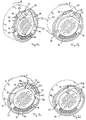
- Figs 5a to 5d show in perspective a plane E section of the counterplug 21 from Fig 4.
- the section runs parallel to the guide rail 32 so that the spring chamber 36 becomes visible. From inside to outside it is possible to see the counterplug housing 22 with the chambers 27.
- the spring chamber 36 Between the inner circumference 62 of the bayonet ring 23 and the shell surface 65 of the counterplug 22 is located the spring chamber 36.
- On the shell surface 65 is molded in the 12 o'clock position a locking lug 69, framed by a ramp 67 and a vertical plane 68.
- the cross-rail 37 which belongs to the counterplug housing 22 and which secures one end of a tension spring 66 located in the spring chamber 36.
- the bayonet ring 23 Projecting further outwards can be seen the bayonet ring 23 with a sliding rail 44, offset inwards (in a position intermediate between 9 and 12 o'clock). On this are molded both the cross-rails 45 and 46.
- An inward-pointing locking hook is molded on one side of the outer shell surface 43 of the bayonet ring 23 and is aligned with the said surface.
- the locking hook has a substantively triangular inward-pointing locking lug 71 on which is molded an inward-pointing cubical block 72 which slides on the shell surface 65 of the counterplug housing 22.
- At the free end of the locking hook 70 is an aperture 74 into which the locking hook 73 projects.
- the second fastening cross-rail 78 of the tension spring 66 is molded on, starting clockwise from the locking hook 70 and offset by a certain angle.
- the collar 24 has two recesses 58a and 58b where the first recess 58a is located over the sliding rail 44 (this is not true of 58b) . Projecting into the said recess 58a, a slightly inward-pointing tongue 79 is molded on the collar 24, so that its front part can rest on sliding rail 44, as shown in Fig 5a.
- Fig 5a In Fig 5a can be seen the condition on delivery of the counterplug. In this condition, the block 72 rests against the locking lug 68. The tension spring 66 is extended as far as it can be. The tongue 79 between rails 45 and 46 is in the 10 o'clock position.
- plug 1 is fastened to a housing wall, that is to say, when the counterplug is pushed onto the said plug 1 as shown in Fig 6b, the counterplug housing 22 cannot rotate because of the codings 10 and 33, since these are cross-engaged. Therefore the housing 22 of the counterplug 21 shown in Figs 5a to 5d will not change its position, that is to say, the locking lug 69 will remain in the 12 o'clock position and the cross-rail 37 in the 9 o'clock position.
- the spring under tension 66 therefore contracts, so that the fastening rail 78 of the bayonet ring 23 which has hitherto been in the 1 o'clock position will now be drawn clockwise into the 4 o'clock position (see Fig 6c) .
- the pegs 40 to 42 of the bayonet ring 23 will simultaneously slide on end 16 of the sliding rails 4 to 6 and lock the plug connector.
- the spring 66 can be under slight tension so that the pegs 40 to 42 will be held against the end 16 of the sliding rail.
- Figs 5 c and 6a show the counterplug in the closed position.
- the collar 24 is turned in the direction A of the arrow (anti-clockwise) .
- the projections 59 and 60 push against the shoulders 61 and 62 or may already be lying against shoulders 61 and 62 and thereby engage the bayonet ring 23 (see Fig 4) .
- the counterplug housing 22 is fast and therefore not able to move.
- the collar 24 and the bayonet ring 23 turn in synchronisation (anti-clockwise) where the tongue 79 as shown in Fig 5c (12 o'clock position) is now rotated into the 9 o'clock position.
- block 72 slides on the shell surface 65, arrives at the ramp 67 which lifts the locking hook 70 into the recess 58b and arrives, after passing over locking lug 69, once again on the shell surface 65 and there presses against the vertical plane 68. Since the distance between the crossrail 37 and the fixing rail 78 increases all the time, the spring 66 passes under tension. Simultaneously with the advance of the bayonet ring 23, the pegs 40 to 42 slide out of sliding channels 4 to 6. The lock is loosened, the plug "halves" are guided apart and may break the connection (see Fig 6b). If the locking hook 70 has passed the locking lug 69, the counterplug 21 will then be in the open position.
Landscapes
- Details Of Connecting Devices For Male And Female Coupling (AREA)
- Connector Housings Or Holding Contact Members (AREA)
Applications Claiming Priority (2)
| Application Number | Priority Date | Filing Date | Title |
|---|---|---|---|
| DE19920481 | 1999-05-04 | ||
| DE19920481A DE19920481C1 (de) | 1999-05-04 | 1999-05-04 | Selbstverriegelnde elektrische Steckverbindung, insbesondere für Kfz-Anwendungen |
Publications (2)
| Publication Number | Publication Date |
|---|---|
| EP1050931A1 true EP1050931A1 (fr) | 2000-11-08 |
| EP1050931B1 EP1050931B1 (fr) | 2004-07-28 |
Family
ID=7906921
Family Applications (1)
| Application Number | Title | Priority Date | Filing Date |
|---|---|---|---|
| EP00109073A Expired - Lifetime EP1050931B1 (fr) | 1999-05-04 | 2000-05-02 | Connecteur électrique auto-couplant spécialement pour des applications automobiles |
Country Status (4)
| Country | Link |
|---|---|
| EP (1) | EP1050931B1 (fr) |
| AT (1) | ATE272255T1 (fr) |
| BR (1) | BR0001697A (fr) |
| DE (2) | DE19920481C1 (fr) |
Cited By (9)
| Publication number | Priority date | Publication date | Assignee | Title |
|---|---|---|---|---|
| FR2859424A1 (fr) * | 2003-09-05 | 2005-03-11 | Peugeot Citroen Automobiles Sa | Dispositif de fixation d'equipements portables comprenant des moyens integres pour raccorder cet equipement au reseau electrique ou analogique ou numerique d'un vehicule automobile, et vehicule equipe d'un tel dispositif |
| CN105940569A (zh) * | 2014-01-31 | 2016-09-14 | 理想工业公司 | 插头连接器 |
| US9502824B2 (en) | 2014-05-23 | 2016-11-22 | Itt Manufacturing Enterprises, Llc | Electrical connector |
| CN108327661A (zh) * | 2018-02-12 | 2018-07-27 | 安徽江淮汽车集团股份有限公司 | 一种防止导线脱出的汽车插件 |
| USD833978S1 (en) | 2016-04-22 | 2018-11-20 | Westinghouse Air Brake Technologies Corporation | Rail car power connector |
| US10199766B2 (en) * | 2016-04-22 | 2019-02-05 | Westinghouse Air Brake Technologies Corporation | Breakaway railcar power connector |
| CN111342302A (zh) * | 2018-12-19 | 2020-06-26 | 施耐德电器工业公司 | 电连接点 |
| DE102019130491B3 (de) * | 2019-11-12 | 2020-09-03 | Phoenix Contact Gmbh & Co. Kg | Elektrisches Steckverbindersystem mit Sperrelement |
| EP4096027A1 (fr) * | 2021-05-26 | 2022-11-30 | Lémo S.A. | Connecteur enfichable modulaire circulaire |
Families Citing this family (5)
| Publication number | Priority date | Publication date | Assignee | Title |
|---|---|---|---|---|
| JP2003036941A (ja) * | 2001-05-15 | 2003-02-07 | Yazaki Corp | 半嵌合防止コネクタへの接続端子の自動挿入方法 |
| DE10225621B3 (de) * | 2002-06-07 | 2004-01-22 | Nicolay Verwaltungs-Gmbh | Vorrichtung zum elektrischen Verbinden einer Anschlußleitung mit einer Elektrode, insbesondere einer medizintechnischen Hautelektrode |
| US8801453B1 (en) | 2013-02-21 | 2014-08-12 | Bourns, Inc. | Rotary connector having a housing and a locking ring |
| CN107813774B (zh) * | 2017-10-25 | 2019-09-24 | 安徽江淮汽车集团股份有限公司 | 一种汽车插件 |
| CN115663537B (zh) * | 2022-11-21 | 2023-03-10 | 天津吉诺科技有限公司 | 一种防松式屏蔽连接结构 |
Citations (3)
| Publication number | Priority date | Publication date | Assignee | Title |
|---|---|---|---|---|
| US3848950A (en) * | 1972-09-07 | 1974-11-19 | G & H Technology | Electrical connector |
| EP0620615A2 (fr) * | 1993-04-16 | 1994-10-19 | Sumitomo Wiring Systems, Ltd. | Connecteur avec guide rotatif |
| US5662488A (en) * | 1996-10-31 | 1997-09-02 | Alden; Peter H. | Quick connect coupling system for rapidly joining connectors and/or other elongated bodies |
Family Cites Families (1)
| Publication number | Priority date | Publication date | Assignee | Title |
|---|---|---|---|---|
| JP2779104B2 (ja) * | 1992-11-12 | 1998-07-23 | 日本原子力研究所 | 簡易着脱電気コネクター |
-
1999
- 1999-05-04 DE DE19920481A patent/DE19920481C1/de not_active Expired - Fee Related
-
2000
- 2000-05-02 DE DE60012409T patent/DE60012409D1/de not_active Expired - Lifetime
- 2000-05-02 AT AT00109073T patent/ATE272255T1/de not_active IP Right Cessation
- 2000-05-02 EP EP00109073A patent/EP1050931B1/fr not_active Expired - Lifetime
- 2000-05-04 BR BR0001697-7A patent/BR0001697A/pt not_active IP Right Cessation
Patent Citations (3)
| Publication number | Priority date | Publication date | Assignee | Title |
|---|---|---|---|---|
| US3848950A (en) * | 1972-09-07 | 1974-11-19 | G & H Technology | Electrical connector |
| EP0620615A2 (fr) * | 1993-04-16 | 1994-10-19 | Sumitomo Wiring Systems, Ltd. | Connecteur avec guide rotatif |
| US5662488A (en) * | 1996-10-31 | 1997-09-02 | Alden; Peter H. | Quick connect coupling system for rapidly joining connectors and/or other elongated bodies |
Cited By (16)
| Publication number | Priority date | Publication date | Assignee | Title |
|---|---|---|---|---|
| FR2859424A1 (fr) * | 2003-09-05 | 2005-03-11 | Peugeot Citroen Automobiles Sa | Dispositif de fixation d'equipements portables comprenant des moyens integres pour raccorder cet equipement au reseau electrique ou analogique ou numerique d'un vehicule automobile, et vehicule equipe d'un tel dispositif |
| CN105940569A (zh) * | 2014-01-31 | 2016-09-14 | 理想工业公司 | 插头连接器 |
| CN105940569B (zh) * | 2014-01-31 | 2019-11-12 | 理想工业公司 | 插头连接器 |
| US9502824B2 (en) | 2014-05-23 | 2016-11-22 | Itt Manufacturing Enterprises, Llc | Electrical connector |
| USD898672S1 (en) | 2016-04-22 | 2020-10-13 | Westinghouse Air Brake Technologies Corporation | Power connector |
| USD833978S1 (en) | 2016-04-22 | 2018-11-20 | Westinghouse Air Brake Technologies Corporation | Rail car power connector |
| US10199766B2 (en) * | 2016-04-22 | 2019-02-05 | Westinghouse Air Brake Technologies Corporation | Breakaway railcar power connector |
| USD900751S1 (en) | 2016-04-22 | 2020-11-03 | Westinghouse Air Brake Technologies Corporation | Power connector |
| CN108327661A (zh) * | 2018-02-12 | 2018-07-27 | 安徽江淮汽车集团股份有限公司 | 一种防止导线脱出的汽车插件 |
| CN108327661B (zh) * | 2018-02-12 | 2019-10-01 | 安徽江淮汽车集团股份有限公司 | 一种防止导线脱出的汽车插件 |
| CN111342302A (zh) * | 2018-12-19 | 2020-06-26 | 施耐德电器工业公司 | 电连接点 |
| CN111342302B (zh) * | 2018-12-19 | 2023-08-04 | 施耐德电器工业公司 | 电连接点 |
| DE102019130491B3 (de) * | 2019-11-12 | 2020-09-03 | Phoenix Contact Gmbh & Co. Kg | Elektrisches Steckverbindersystem mit Sperrelement |
| EP4096027A1 (fr) * | 2021-05-26 | 2022-11-30 | Lémo S.A. | Connecteur enfichable modulaire circulaire |
| WO2022248291A1 (fr) * | 2021-05-26 | 2022-12-01 | Lemo Sa | Connecteur enfichable modulaire circulaire |
| US12095198B2 (en) | 2021-05-26 | 2024-09-17 | Lemo Sa | Circular modular pluggable connector |
Also Published As
| Publication number | Publication date |
|---|---|
| DE60012409D1 (de) | 2004-09-02 |
| EP1050931B1 (fr) | 2004-07-28 |
| ATE272255T1 (de) | 2004-08-15 |
| DE19920481C1 (de) | 2001-01-18 |
| BR0001697A (pt) | 2000-12-26 |
Similar Documents
| Publication | Publication Date | Title |
|---|---|---|
| EP1050931B1 (fr) | Connecteur électrique auto-couplant spécialement pour des applications automobiles | |
| CN1956269B (zh) | 用于电连接器组件的电缆退出组件 | |
| US11050192B2 (en) | Electric connector with connector position assurance | |
| US5573417A (en) | Feeding connector | |
| CA2205742C (fr) | Raccord electrique pour generateur de gaz de coussin gonflable | |
| US9099803B2 (en) | Joint connector and assembling method thereof | |
| US5618204A (en) | Circular bulkhead connector assembly | |
| EP1187265B1 (fr) | Connecteur étanche | |
| EP1548892B1 (fr) | Connecteur electrique | |
| EP1054477B1 (fr) | Connecteur électrique à douille, notamment pour véhicule automobile | |
| US6361378B1 (en) | Connector with a side retainer | |
| EP3955395B1 (fr) | Ensemble connecteur avec levier à fente symétrique étanche | |
| US10490938B2 (en) | Electrical connector with assist lever | |
| CN107240810B (zh) | 具有防水功能的汽车线束插件 | |
| US10135183B1 (en) | Electrical connector with assist lever | |
| JP2016511520A (ja) | レセプタクル・キャリアを有するコネクタ組立体 | |
| KR20030026231A (ko) | 결합 보조 장치를 갖는 커넥터 | |
| EP3386040B1 (fr) | Connecteur et méthode de production d'une connexion | |
| EP1009065B1 (fr) | Connecteur étanche | |
| US10270207B1 (en) | Electrical connector with assist lever | |
| EP0140628A2 (fr) | Connecteur électrique avec moyen de blocage | |
| EP0512323B1 (fr) | Construction d'un connecteur | |
| CN107978894B (zh) | 成角度的插接连接器及其制造方法 | |
| EP0667654B1 (fr) | Connecteur électrique ayant un système amélioré de verrouillage et déverrouillage | |
| EP1701414B1 (fr) | Connecteur électrique |
Legal Events
| Date | Code | Title | Description |
|---|---|---|---|
| PUAI | Public reference made under article 153(3) epc to a published international application that has entered the european phase |
Free format text: ORIGINAL CODE: 0009012 |
|
| AK | Designated contracting states |
Kind code of ref document: A1 Designated state(s): AT BE CH CY DE DK ES FI FR GB GR IE IT LI LU MC NL PT SE |
|
| AX | Request for extension of the european patent |
Free format text: AL;LT;LV;MK;RO;SI |
|
| 17P | Request for examination filed |
Effective date: 20001201 |
|
| AKX | Designation fees paid |
Free format text: AT BE CH CY DE DK ES FI FR GB GR IE IT LI LU MC NL PT SE |
|
| 17Q | First examination report despatched |
Effective date: 20021202 |
|
| GRAP | Despatch of communication of intention to grant a patent |
Free format text: ORIGINAL CODE: EPIDOSNIGR1 |
|
| GRAS | Grant fee paid |
Free format text: ORIGINAL CODE: EPIDOSNIGR3 |
|
| RAP1 | Party data changed (applicant data changed or rights of an application transferred) |
Owner name: FCI |
|
| GRAA | (expected) grant |
Free format text: ORIGINAL CODE: 0009210 |
|
| AK | Designated contracting states |
Kind code of ref document: B1 Designated state(s): AT BE CH CY DE DK ES FI FR GB GR IE IT LI LU MC NL PT SE |
|
| PG25 | Lapsed in a contracting state [announced via postgrant information from national office to epo] |
Ref country code: BE Free format text: LAPSE BECAUSE OF FAILURE TO SUBMIT A TRANSLATION OF THE DESCRIPTION OR TO PAY THE FEE WITHIN THE PRESCRIBED TIME-LIMIT Effective date: 20040728 Ref country code: LI Free format text: LAPSE BECAUSE OF FAILURE TO SUBMIT A TRANSLATION OF THE DESCRIPTION OR TO PAY THE FEE WITHIN THE PRESCRIBED TIME-LIMIT Effective date: 20040728 Ref country code: NL Free format text: LAPSE BECAUSE OF FAILURE TO SUBMIT A TRANSLATION OF THE DESCRIPTION OR TO PAY THE FEE WITHIN THE PRESCRIBED TIME-LIMIT Effective date: 20040728 Ref country code: AT Free format text: LAPSE BECAUSE OF FAILURE TO SUBMIT A TRANSLATION OF THE DESCRIPTION OR TO PAY THE FEE WITHIN THE PRESCRIBED TIME-LIMIT Effective date: 20040728 Ref country code: CH Free format text: LAPSE BECAUSE OF FAILURE TO SUBMIT A TRANSLATION OF THE DESCRIPTION OR TO PAY THE FEE WITHIN THE PRESCRIBED TIME-LIMIT Effective date: 20040728 Ref country code: FI Free format text: LAPSE BECAUSE OF FAILURE TO SUBMIT A TRANSLATION OF THE DESCRIPTION OR TO PAY THE FEE WITHIN THE PRESCRIBED TIME-LIMIT Effective date: 20040728 |
|
| REG | Reference to a national code |
Ref country code: GB Ref legal event code: FG4D |
|
| REG | Reference to a national code |
Ref country code: CH Ref legal event code: EP |
|
| REG | Reference to a national code |
Ref country code: IE Ref legal event code: FG4D |
|
| REF | Corresponds to: |
Ref document number: 60012409 Country of ref document: DE Date of ref document: 20040902 Kind code of ref document: P |
|
| PG25 | Lapsed in a contracting state [announced via postgrant information from national office to epo] |
Ref country code: GR Free format text: LAPSE BECAUSE OF FAILURE TO SUBMIT A TRANSLATION OF THE DESCRIPTION OR TO PAY THE FEE WITHIN THE PRESCRIBED TIME-LIMIT Effective date: 20041028 Ref country code: DK Free format text: LAPSE BECAUSE OF FAILURE TO SUBMIT A TRANSLATION OF THE DESCRIPTION OR TO PAY THE FEE WITHIN THE PRESCRIBED TIME-LIMIT Effective date: 20041028 Ref country code: SE Free format text: LAPSE BECAUSE OF FAILURE TO SUBMIT A TRANSLATION OF THE DESCRIPTION OR TO PAY THE FEE WITHIN THE PRESCRIBED TIME-LIMIT Effective date: 20041028 |
|
| PG25 | Lapsed in a contracting state [announced via postgrant information from national office to epo] |
Ref country code: DE Free format text: LAPSE BECAUSE OF FAILURE TO SUBMIT A TRANSLATION OF THE DESCRIPTION OR TO PAY THE FEE WITHIN THE PRESCRIBED TIME-LIMIT Effective date: 20041029 |
|
| PG25 | Lapsed in a contracting state [announced via postgrant information from national office to epo] |
Ref country code: ES Free format text: LAPSE BECAUSE OF FAILURE TO SUBMIT A TRANSLATION OF THE DESCRIPTION OR TO PAY THE FEE WITHIN THE PRESCRIBED TIME-LIMIT Effective date: 20041108 |
|
| NLV1 | Nl: lapsed or annulled due to failure to fulfill the requirements of art. 29p and 29m of the patents act | ||
| REG | Reference to a national code |
Ref country code: CH Ref legal event code: PL |
|
| PGFP | Annual fee paid to national office [announced via postgrant information from national office to epo] |
Ref country code: GB Payment date: 20050427 Year of fee payment: 6 |
|
| PG25 | Lapsed in a contracting state [announced via postgrant information from national office to epo] |
Ref country code: LU Free format text: LAPSE BECAUSE OF NON-PAYMENT OF DUE FEES Effective date: 20050502 Ref country code: CY Free format text: LAPSE BECAUSE OF FAILURE TO SUBMIT A TRANSLATION OF THE DESCRIPTION OR TO PAY THE FEE WITHIN THE PRESCRIBED TIME-LIMIT Effective date: 20050502 Ref country code: IE Free format text: LAPSE BECAUSE OF NON-PAYMENT OF DUE FEES Effective date: 20050502 |
|
| PG25 | Lapsed in a contracting state [announced via postgrant information from national office to epo] |
Ref country code: MC Free format text: LAPSE BECAUSE OF NON-PAYMENT OF DUE FEES Effective date: 20050531 |
|
| ET | Fr: translation filed | ||
| PLBE | No opposition filed within time limit |
Free format text: ORIGINAL CODE: 0009261 |
|
| STAA | Information on the status of an ep patent application or granted ep patent |
Free format text: STATUS: NO OPPOSITION FILED WITHIN TIME LIMIT |
|
| 26N | No opposition filed |
Effective date: 20050429 |
|
| REG | Reference to a national code |
Ref country code: IE Ref legal event code: MM4A |
|
| PG25 | Lapsed in a contracting state [announced via postgrant information from national office to epo] |
Ref country code: GB Free format text: LAPSE BECAUSE OF NON-PAYMENT OF DUE FEES Effective date: 20060502 |
|
| GBPC | Gb: european patent ceased through non-payment of renewal fee |
Effective date: 20060502 |
|
| PG25 | Lapsed in a contracting state [announced via postgrant information from national office to epo] |
Ref country code: PT Free format text: LAPSE BECAUSE OF NON-PAYMENT OF DUE FEES Effective date: 20041228 |
|
| PGFP | Annual fee paid to national office [announced via postgrant information from national office to epo] |
Ref country code: IT Payment date: 20100513 Year of fee payment: 11 |
|
| REG | Reference to a national code |
Ref country code: FR Ref legal event code: TP Owner name: FCI AUTOMOTIVE HOLDING, FR Effective date: 20110912 Ref country code: FR Ref legal event code: CD Owner name: FCI AUTOMOTIVE HOLDING, FR Effective date: 20110912 |
|
| REG | Reference to a national code |
Ref country code: FR Ref legal event code: GC Effective date: 20111020 |
|
| PG25 | Lapsed in a contracting state [announced via postgrant information from national office to epo] |
Ref country code: IT Free format text: LAPSE BECAUSE OF NON-PAYMENT OF DUE FEES Effective date: 20110502 |
|
| REG | Reference to a national code |
Ref country code: FR Ref legal event code: TP Owner name: DELPHI INTERNATIONAL OPERATIONS LUXEMBOURG S.A, LU Effective date: 20140715 |
|
| REG | Reference to a national code |
Ref country code: FR Ref legal event code: PLFP Year of fee payment: 17 |
|
| REG | Reference to a national code |
Ref country code: FR Ref legal event code: PLFP Year of fee payment: 18 |
|
| REG | Reference to a national code |
Ref country code: FR Ref legal event code: PLFP Year of fee payment: 19 |
|
| PGFP | Annual fee paid to national office [announced via postgrant information from national office to epo] |
Ref country code: FR Payment date: 20190527 Year of fee payment: 20 |