EP1050945A1 - Unite de commande de generateur de courant alternatif de vehicule - Google Patents
Unite de commande de generateur de courant alternatif de vehicule Download PDFInfo
- Publication number
- EP1050945A1 EP1050945A1 EP98954726A EP98954726A EP1050945A1 EP 1050945 A1 EP1050945 A1 EP 1050945A1 EP 98954726 A EP98954726 A EP 98954726A EP 98954726 A EP98954726 A EP 98954726A EP 1050945 A1 EP1050945 A1 EP 1050945A1
- Authority
- EP
- European Patent Office
- Prior art keywords
- generator
- voltage
- rotation speed
- gradually
- increasing
- Prior art date
- Legal status (The legal status is an assumption and is not a legal conclusion. Google has not performed a legal analysis and makes no representation as to the accuracy of the status listed.)
- Granted
Links
Images
Classifications
-
- H—ELECTRICITY
- H02—GENERATION; CONVERSION OR DISTRIBUTION OF ELECTRIC POWER
- H02P—CONTROL OR REGULATION OF ELECTRIC MOTORS, ELECTRIC GENERATORS OR DYNAMO-ELECTRIC CONVERTERS; CONTROLLING TRANSFORMERS, REACTORS OR CHOKE COILS
- H02P9/00—Arrangements for controlling electric generators for the purpose of obtaining a desired output
- H02P9/04—Control effected upon non-electric prime mover and dependent upon electric output value of the generator
-
- H—ELECTRICITY
- H02—GENERATION; CONVERSION OR DISTRIBUTION OF ELECTRIC POWER
- H02J—ELECTRIC POWER NETWORKS; CIRCUIT ARRANGEMENTS OR SYSTEMS FOR SUPPLYING OR DISTRIBUTING ELECTRIC POWER; SYSTEMS FOR STORING ELECTRIC ENERGY
- H02J7/00—Circuit arrangements for charging or discharging batteries or for supplying loads from batteries
- H02J7/14—Circuit arrangements for charging or discharging batteries or for supplying loads from batteries for charging batteries from dynamo-electric generators driven at varying speed, e.g. on vehicle
- H02J7/16—Regulation of the charging current or voltage by variation of field
- H02J7/24—Regulation of the charging current or voltage by variation of field using discharge tubes or semiconductor devices
- H02J7/2434—Regulation of the charging current or voltage by variation of field using discharge tubes or semiconductor devices with pulse modulation
-
- Y—GENERAL TAGGING OF NEW TECHNOLOGICAL DEVELOPMENTS; GENERAL TAGGING OF CROSS-SECTIONAL TECHNOLOGIES SPANNING OVER SEVERAL SECTIONS OF THE IPC; TECHNICAL SUBJECTS COVERED BY FORMER USPC CROSS-REFERENCE ART COLLECTIONS [XRACs] AND DIGESTS
- Y02—TECHNOLOGIES OR APPLICATIONS FOR MITIGATION OR ADAPTATION AGAINST CLIMATE CHANGE
- Y02T—CLIMATE CHANGE MITIGATION TECHNOLOGIES RELATED TO TRANSPORTATION
- Y02T10/00—Road transport of goods or passengers
- Y02T10/80—Technologies aiming to reduce greenhouse gasses emissions common to all road transportation technologies
- Y02T10/92—Energy efficient charging or discharging systems for batteries, ultracapacitors, supercapacitors or double-layer capacitors specially adapted for vehicles
Definitions
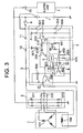
- the generator 1 When engine operation is started, the generator 1 is rotationally driven, whereby generation of electricity is started. In this state, a divided voltage obtained by dividing a generated voltage of the generator 1 with voltage dividing resistors 301 and 302 is compared with a reference voltage derived from voltage division of a constant voltage supplied from a constant-voltage power source A with voltage dividing resistors 303 and 304 by means of a comparator 305 of a voltage regulator 3.
- the resistance value of the charging resistor 402 for the capacitor 404 constituting a part of the smoothing circuit 4 is selected to be small while that of the discharging resistor 405 is selected large.
- the value of the time constant for electric charging is set short or small (e.g. not greater than 0.5 sec.), whereas the time constant for electric discharge is set long or large (e.g. not smaller than 0.5 sec.), whereby such operation is ordinarily realized that the output of the comparator 601 becomes substantially equivalent to the output of the comparator 305 which constitutes a part of the voltage detecting circuit.
- the charging time constant of the smoothing circuit is set short while the discharging time constant is set long, wherein each of the time constants mentioned above is always set to a fixed value. Consequently, the ratio of conduction of the power transistor 308 increases progressively or gradually in dependence on the magnitude of the discharging time constant which is effective when the electric load 9 is turned on and finally reaches a predetermined conducting rate after lapse of a predetermined time.
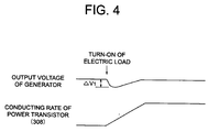
- the generator output voltage once falls temporarily to ⁇ V1 upon turning-on or electric energization of the electric load 9 and thereafter increases gradually in conformance with the conducting rate of the power transistor 308.
- the conventional apparatus is certainly effective for reducing decrease of the engine rotation number (rpm) by increasing gradually the output power of the generator when the engine by which the generator is driven is in the idling operation state.
- the operation of gradually increasing the generator output is effective equally in a high-speed rotation state where the engine output allows a margin, the output voltage of the generator always falls every time the electric load is turned on, which in turn brings about variation in the output states of the loads already set to the on-state such as variation in luminance of lamps installed on instrumentation panels, room lamps, etc. which is of course uncomfortable for the driver, giving rise to a problem.
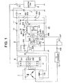
- FIG. 1 is a diagram showing a structure of a control apparatus for a vehicle-onboard AC generator according to a first implementation mode of the invention concerned.
- same reference numerals as those used in Fig. 3 denote same or equivalent parts. Shown in Fig.
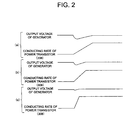
- FIG. 2 at (a) is a characteristic diagram for illustrating a relation between a generator output voltage and a conducting rate of a power transistor in an idling operation state of an engine
- FIG. (b) is a characteristic diagram for illustrating a relation between a generator output voltage and a conducting rate of the power transistor in a moderate-speed rotation state of the engine
- FIG. (c) is a characteristic diagram for illustrating a relation between an output voltage of the generator and a conducting rate of the power transistor in a high-speed rotation state of the engine.
- reference numeral 13 denotes a F-V converter which constitutes a rotation speed detecting means.
- This F-V converter 13 is designed for detecting a rotation frequency of the generator 1 on the basis of a frequency of an AC voltage induced in the armature coil 101 to thereby convert the rotation frequency (F) into a DC voltage (V).
- the DC voltage (V) resulting from the conversion assumes a large value in proportion to the rotation frequency (F).
- a transistor 406 is employed in place of the discharging resistor 405, wherein the collector and the emitter of the transistor 406 are connected in parallel to the capacitor 404 with the base of the transistor 406 being connected to that of the NPN transistor 407.
- the F-V converter 13 serves for detecting the rotation frequency of the generator 1 in the idling state of the engine, to thereby convert the rotation frequency into a DC voltage which is then applied to the base of the transistor 407 constituting a part of the constant-current circuit by way of the current limiting resistor 408.
- the transistor 602 is periodically turned on and off with the ON/OFF duty ratio being gradually increased until it is detected that the output voltage of the generator 1 has reached a predetermined value through comparison of the discharge voltage of the smoothing circuit 4 and the triangular waveform voltage generated by the triangular waveform generator 5.
- the power transistor 308 is also turned on and off in conformance with the turn-on/off operation of the transistor 602.
- the field current flowing through the field coil 102 thus undergoes on/off control by means of the power transistor 308, whereby the output voltage of the generator 1 is caused to increase or rise gradually and gently up to a predetermined value in conformance with the discharge characteristic determined by the discharging time constant, as a result of which decreasing of the engine rotation can be reduced.
- the converted voltage outputted from the F-V converter 13 and having higher level than that in the idling operation state is inputted to the constant-current circuit, whereby the base current at the moderate-speed operation state of the engine is fed to the base of the transistor 406 as the base current, as illustrated in the same figure at (b).
- the power transistor 308 is also turned on and off in conformance with the turn-on/off operation of the transistor 602.
- the field current flowing through the field coil 102 thus undergoes on/off control by the power transistor 308, whereby the output voltage of the generator 1 is caused to increase or rise gradually and gently up to the predetermined value in accordance with the discharge characteristic determined by the discharging time constant, as a result of which decreasing of the output voltage of the generator can be reduced.
- the discharging time constant may be regarded smaller than that in the moderate-speed operation state.
- the transistor 602 is periodically turned on and off with the ON/OFF duty ratio being rapidly increased until it is detected that the output voltage of the generator 1 has reached the predetermined value through comparison of the discharge voltage of the smoothing circuit 4 and the triangular waveform voltage generated by the triangular waveform generator 5.
- the power transistor 308 is also turned on and off with the duty ratio which conforms with the on/off operation of the transistor 602.
- the field current flowing through the field coil 102 thus undergoes on/off control by the power transistor 308, whereby the output voltage of the generator 1 is caused to increase or rise rapidly up to the predetermined value in accordance with the discharge characteristic determined by the discharging time constant, as a result of which decreasing or fall of the generator output voltage can be reduced when compared with that in the moderate-speed rotation state of the engine.
- the rate at which the generator output voltage is increased gradually is increased in conformance with the rotation speed of the generator which in turn depends on the engine rotation number, wherein in the low speed operation state of the engine, the time period during which the generator output voltage is caused to increase gradually is lengthened to thereby reduce decreasing or fall of the engine rotation, whereas in the high-speed operation state of the engine, the time period during which the generator output voltage is caused to increase gradually is shortened to thereby reduce lowering of the generator output voltage.
Landscapes
- Engineering & Computer Science (AREA)
- Power Engineering (AREA)
- Control Of Eletrric Generators (AREA)
- Control Of Vehicle Engines Or Engines For Specific Uses (AREA)
- Control Of Charge By Means Of Generators (AREA)
Applications Claiming Priority (1)
| Application Number | Priority Date | Filing Date | Title |
|---|---|---|---|
| PCT/JP1998/005185 WO2000030236A1 (fr) | 1998-11-18 | 1998-11-18 | Unite de commande de generateur de courant alternatif de vehicule |
Publications (3)
| Publication Number | Publication Date |
|---|---|
| EP1050945A1 true EP1050945A1 (fr) | 2000-11-08 |
| EP1050945A4 EP1050945A4 (fr) | 2001-04-04 |
| EP1050945B1 EP1050945B1 (fr) | 2009-11-04 |
Family
ID=14209419
Family Applications (1)
| Application Number | Title | Priority Date | Filing Date |
|---|---|---|---|
| EP98954726A Expired - Lifetime EP1050945B1 (fr) | 1998-11-18 | 1998-11-18 | Unite de commande de generateur de courant alternatif de vehicule |
Country Status (7)
| Country | Link |
|---|---|
| US (1) | US6271649B1 (fr) |
| EP (1) | EP1050945B1 (fr) |
| JP (1) | JP3574146B2 (fr) |
| KR (1) | KR100376923B1 (fr) |
| CN (1) | CN1112752C (fr) |
| DE (1) | DE69841274D1 (fr) |
| WO (1) | WO2000030236A1 (fr) |
Families Citing this family (20)
| Publication number | Priority date | Publication date | Assignee | Title |
|---|---|---|---|---|
| JP4224932B2 (ja) * | 2000-08-07 | 2009-02-18 | 株式会社デンソー | 車両用交流発電機の電圧制御装置 |
| US6700353B2 (en) * | 2001-04-16 | 2004-03-02 | Denso Corporation | Battery charging system and vehicle generator control system |
| US6534959B1 (en) * | 2001-08-31 | 2003-03-18 | Delphi Technologies, Inc. | Voltage sensing for automotive voltage regulator |
| US20060102744A1 (en) * | 2002-10-21 | 2006-05-18 | Uri Arkasjevski | Apparatus and method for cleaning or de-icing vehicle elements |
| WO2005031964A1 (fr) * | 2003-09-25 | 2005-04-07 | Mitsubishi Denki Kabushiki Kaisha | Controleur d'alternateur pour vehicule |
| JP4450613B2 (ja) * | 2003-12-17 | 2010-04-14 | 三菱電機株式会社 | 車両用交流発電機の制御装置 |
| JP4120603B2 (ja) * | 2004-03-16 | 2008-07-16 | 株式会社デンソー | 車両用発電装置 |
| JP4151604B2 (ja) * | 2004-04-23 | 2008-09-17 | 株式会社デンソー | 車両用発電制御装置 |
| JP4151642B2 (ja) * | 2004-10-25 | 2008-09-17 | 株式会社デンソー | 車両用発電制御システム |
| JP4124209B2 (ja) * | 2005-03-23 | 2008-07-23 | 株式会社デンソー | 発電制御装置 |
| JP4501866B2 (ja) * | 2006-02-16 | 2010-07-14 | 株式会社デンソー | 車両用発電機 |
| JP4596185B2 (ja) * | 2007-08-29 | 2010-12-08 | 株式会社デンソー | 車両用電圧制御装置 |
| JP2009112169A (ja) * | 2007-10-31 | 2009-05-21 | Honda Motor Co Ltd | 発電機の出力制御装置 |
| JP4798144B2 (ja) * | 2008-01-31 | 2011-10-19 | トヨタ自動車株式会社 | オルタネータ制御装置 |
| JP5430672B2 (ja) * | 2009-11-20 | 2014-03-05 | 三菱電機株式会社 | 車両用交流発電機の制御装置 |
| DE102010029967B4 (de) | 2010-06-11 | 2025-11-06 | Seg Automotive Germany Gmbh | Verfahren und Vorrichtung zum Ausgleich eines Einbruchs der Ausgangsspannung eines Kraftfahrzeuggenerators |
| JP5452654B2 (ja) * | 2012-04-11 | 2014-03-26 | 三菱電機株式会社 | 車両用交流発電機の制御装置 |
| CN102710199B (zh) * | 2012-06-13 | 2015-04-01 | 江苏苏美达机电产业有限公司 | 一种发电机励磁控制系统 |
| JP5595447B2 (ja) * | 2012-06-15 | 2014-09-24 | 三菱電機株式会社 | 車輌用交流発電機の制御装置及び制御方法 |
| BR112015023575A8 (pt) | 2013-03-21 | 2019-12-03 | Honda Motor Co Ltd | unidade de geração de potência e método para controlar motor gerador". |
Family Cites Families (16)
| Publication number | Priority date | Publication date | Assignee | Title |
|---|---|---|---|---|
| JPS6070936A (ja) | 1983-09-22 | 1985-04-22 | 株式会社デンソー | 車両充電発電機用制御装置 |
| DE3713007A1 (de) | 1987-04-16 | 1988-10-27 | Hydro Geraetebau Gmbh & Co Kg | Einrichtung zum hochbocken von flugzeugen |
| JP2522797Y2 (ja) * | 1987-08-25 | 1997-01-16 | 三菱電機株式会社 | 車両用交流発電機の制御装置 |
| US5270575A (en) | 1989-11-30 | 1993-12-14 | Mitsubishi Jidosha Kogyo Kabushiki Kaisha | Device for controlling change in idling |
| JP2528995B2 (ja) | 1990-03-19 | 1996-08-28 | 株式会社日立製作所 | 車載発電機の制御システム |
| JP3536305B2 (ja) * | 1991-10-31 | 2004-06-07 | 株式会社デンソー | オルタネータ出力電圧制御装置 |
| US5225764A (en) * | 1991-11-29 | 1993-07-06 | Sgs-Thomson Microelectronics, Inc. | Voltage regulating circuitry to vary the alternator field coil drive at a rate dependent upon a rotor velocity signal |
| GB9125480D0 (en) | 1991-11-29 | 1992-01-29 | Pilkington Visioncare Holdings | Polymeric bifocal lens production process |
| DE4220634C2 (de) | 1992-06-24 | 1996-04-11 | Daimler Benz Aerospace Ag | Justiervorrichtung |
| JP3402475B2 (ja) * | 1992-09-08 | 2003-05-06 | 株式会社デンソー | 車両用発電機の励磁電流制御装置 |
| JPH06225599A (ja) * | 1992-10-14 | 1994-08-12 | Ford Motor Co | 自動車用発電機の出力電力制御装置 |
| JP3289411B2 (ja) * | 1993-06-07 | 2002-06-04 | 株式会社デンソー | 車両用発電機の電圧制御装置 |
| JP3321653B2 (ja) * | 1993-06-30 | 2002-09-03 | マツダ株式会社 | オルタネータ制御装置 |
| JPH08331897A (ja) * | 1995-06-05 | 1996-12-13 | Mitsubishi Electric Corp | 車両用交流発電機の制御装置 |
| JP3613845B2 (ja) * | 1995-07-17 | 2005-01-26 | 株式会社デンソー | 車両用発電装置 |
| FR2744853B1 (fr) * | 1996-02-08 | 1998-04-30 | Valeo Equip Electr Moteur | Dispositif regulateur de la tension de charge d'une batterie par un alternateur, en fonction d'une tension de reference et de la vitesse de rotation de l'alternateur |
-
1998
- 1998-11-18 JP JP55901499A patent/JP3574146B2/ja not_active Expired - Fee Related
- 1998-11-18 DE DE69841274T patent/DE69841274D1/de not_active Expired - Lifetime
- 1998-11-18 WO PCT/JP1998/005185 patent/WO2000030236A1/fr not_active Ceased
- 1998-11-18 KR KR10-2000-7007305A patent/KR100376923B1/ko not_active Expired - Fee Related
- 1998-11-18 EP EP98954726A patent/EP1050945B1/fr not_active Expired - Lifetime
- 1998-11-18 CN CN98810028A patent/CN1112752C/zh not_active Expired - Fee Related
- 1998-11-18 US US09/509,492 patent/US6271649B1/en not_active Expired - Lifetime
Also Published As
| Publication number | Publication date |
|---|---|
| CN1112752C (zh) | 2003-06-25 |
| JP3574146B2 (ja) | 2004-10-06 |
| KR20010033778A (ko) | 2001-04-25 |
| WO2000030236A1 (fr) | 2000-05-25 |
| US6271649B1 (en) | 2001-08-07 |
| EP1050945A4 (fr) | 2001-04-04 |
| KR100376923B1 (ko) | 2003-03-26 |
| DE69841274D1 (de) | 2009-12-17 |
| EP1050945B1 (fr) | 2009-11-04 |
| CN1275254A (zh) | 2000-11-29 |
Similar Documents
| Publication | Publication Date | Title |
|---|---|---|
| US6271649B1 (en) | Control apparatus for vehicle AC generator | |
| US5061889A (en) | Vehicle ac generator control device for adjusting output voltage in accordance with vehicle conditions | |
| CA1270040A (fr) | Systeme d'alimentation electrique a plusieurs tensions, pour vehicule | |
| US5144220A (en) | Vehicle ac generator control system | |
| US5672954A (en) | Control system for AC generator | |
| US6005372A (en) | Vehicle generator controller | |
| EP0881739B1 (fr) | Régulateur de générateur pour un véhicule | |
| KR100268962B1 (ko) | 차량용 교류 발전기의 제어장치 | |
| US6215284B1 (en) | Control device of A.C. generator for vehicle | |
| JPWO1999038239A1 (ja) | 車両用交流発電機の制御装置 | |
| JPWO1999053596A1 (ja) | 車両用交流発電機の制御装置 | |
| US7106028B2 (en) | Controller of A.C. generator for vehicles | |
| JPWO2000030236A1 (ja) | 車両用交流発電機の制御装置 | |
| US4594975A (en) | Glow plug current supply control system | |
| KR100453666B1 (ko) | 차량용 교류발전기의 전압제어장치 | |
| JPH089567A (ja) | 車両用交流発電機の出力制御方法及び出力制御装置 | |
| JPH0345200A (ja) | 車両用交流発電機の制御装置 | |
| KR100343761B1 (ko) | 차량용 교류발전기의 제어장치 | |
| JPS6053182B2 (ja) | 内燃機関点火装置 | |
| JPH06225474A (ja) | 車両用充電装置 | |
| JPH06165600A (ja) | 交流発電機の発電検出装置 | |
| JPH0611170B2 (ja) | 車両用交流発電機の電圧制御装置 | |
| HK1023001B (en) | Vehicle ac generator control system | |
| JPH0557810B2 (fr) | ||
| JPH04248335A (ja) | 車両用交流発電機の電圧制御装置 |
Legal Events
| Date | Code | Title | Description |
|---|---|---|---|
| PUAI | Public reference made under article 153(3) epc to a published international application that has entered the european phase |
Free format text: ORIGINAL CODE: 0009012 |
|
| 17P | Request for examination filed |
Effective date: 20000420 |
|
| AK | Designated contracting states |
Kind code of ref document: A1 Designated state(s): DE FR GB |
|
| A4 | Supplementary search report drawn up and despatched |
Effective date: 20010219 |
|
| AK | Designated contracting states |
Kind code of ref document: A4 Designated state(s): DE FR GB |
|
| RIC1 | Information provided on ipc code assigned before grant |
Free format text: 7H 02J 7/24 A, 7H 02J 7/16 B, 7H 02P 9/30 B, 7F 02D 29/06 B, 7F 02B 67/00 B, 7H 02J 7/14 B |
|
| RAP1 | Party data changed (applicant data changed or rights of an application transferred) |
Owner name: MITSUBISHI DENKI KABUSHIKI KAISHA |
|
| 17Q | First examination report despatched |
Effective date: 20071109 |
|
| GRAP | Despatch of communication of intention to grant a patent |
Free format text: ORIGINAL CODE: EPIDOSNIGR1 |
|
| GRAS | Grant fee paid |
Free format text: ORIGINAL CODE: EPIDOSNIGR3 |
|
| GRAA | (expected) grant |
Free format text: ORIGINAL CODE: 0009210 |
|
| AK | Designated contracting states |
Kind code of ref document: B1 Designated state(s): DE FR GB |
|
| REG | Reference to a national code |
Ref country code: GB Ref legal event code: FG4D |
|
| REF | Corresponds to: |
Ref document number: 69841274 Country of ref document: DE Date of ref document: 20091217 Kind code of ref document: P |
|
| REG | Reference to a national code |
Ref country code: GB Ref legal event code: S27 Free format text: APPLICATION FILED; APPLICATION TO AMEND SPECIFICATION UNDER SECTION 27 FILED ON 10 FEBRUARY 2010 |
|
| REG | Reference to a national code |
Ref country code: GB Ref legal event code: S27 Free format text: APPLICATION OPEN FOR OPPOSITION; PATENTS FORM 15 GIVING THE COMPTROLLER NOTICE OF OPPOSITION TO THE AMENDMENTS. YOU ALSO NEED TO FILE TWO COPIES OF A STATEMENT SETTING OUT FULLY THE FACTS OF YOUR CASE AND THE RELIEF THAT YOU ARE SEEKING. |
|
| REG | Reference to a national code |
Ref country code: GB Ref legal event code: S27 Free format text: SPECIFICATION AMENDED; APPLICATION FOR AMENDMENT UNDER SECTION 27 FILED ON 10 FEBRUARY 2010, ALLOWED ON 28 JULY 2010 |
|
| PLBE | No opposition filed within time limit |
Free format text: ORIGINAL CODE: 0009261 |
|
| STAA | Information on the status of an ep patent application or granted ep patent |
Free format text: STATUS: NO OPPOSITION FILED WITHIN TIME LIMIT |
|
| 26N | No opposition filed |
Effective date: 20100805 |
|
| REG | Reference to a national code |
Ref country code: GB Ref legal event code: 746 Effective date: 20120430 |
|
| REG | Reference to a national code |
Ref country code: DE Ref legal event code: R084 Ref document number: 69841274 Country of ref document: DE Effective date: 20120425 |
|
| PGFP | Annual fee paid to national office [announced via postgrant information from national office to epo] |
Ref country code: DE Payment date: 20141111 Year of fee payment: 17 Ref country code: GB Payment date: 20141112 Year of fee payment: 17 Ref country code: FR Payment date: 20141110 Year of fee payment: 17 |
|
| REG | Reference to a national code |
Ref country code: DE Ref legal event code: R119 Ref document number: 69841274 Country of ref document: DE |
|
| GBPC | Gb: european patent ceased through non-payment of renewal fee |
Effective date: 20151118 |
|
| REG | Reference to a national code |
Ref country code: FR Ref legal event code: ST Effective date: 20160729 |
|
| PG25 | Lapsed in a contracting state [announced via postgrant information from national office to epo] |
Ref country code: GB Free format text: LAPSE BECAUSE OF NON-PAYMENT OF DUE FEES Effective date: 20151118 Ref country code: DE Free format text: LAPSE BECAUSE OF NON-PAYMENT OF DUE FEES Effective date: 20160601 |
|
| PG25 | Lapsed in a contracting state [announced via postgrant information from national office to epo] |
Ref country code: FR Free format text: LAPSE BECAUSE OF NON-PAYMENT OF DUE FEES Effective date: 20151130 |