EP1051761B1 - Piezoelektrischer aktor - Google Patents
Piezoelektrischer aktor Download PDFInfo
- Publication number
- EP1051761B1 EP1051761B1 EP99973355A EP99973355A EP1051761B1 EP 1051761 B1 EP1051761 B1 EP 1051761B1 EP 99973355 A EP99973355 A EP 99973355A EP 99973355 A EP99973355 A EP 99973355A EP 1051761 B1 EP1051761 B1 EP 1051761B1
- Authority
- EP
- European Patent Office
- Prior art keywords
- electrodes
- blind
- metallic
- actuator
- piezoelectric actuator
- Prior art date
- Legal status (The legal status is an assumption and is not a legal conclusion. Google has not performed a legal analysis and makes no representation as to the accuracy of the status listed.)
- Expired - Lifetime
Links
- 239000000463 material Substances 0.000 claims description 6
- 238000002347 injection Methods 0.000 claims description 5
- 239000007924 injection Substances 0.000 claims description 5
- 238000002485 combustion reaction Methods 0.000 claims description 2
- 238000006073 displacement reaction Methods 0.000 claims 1
- 239000000446 fuel Substances 0.000 description 4
- 230000017525 heat dissipation Effects 0.000 description 4
- 210000000056 organ Anatomy 0.000 description 4
- 229910010293 ceramic material Inorganic materials 0.000 description 3
- 239000002826 coolant Substances 0.000 description 3
- 238000001816 cooling Methods 0.000 description 3
- 239000007788 liquid Substances 0.000 description 3
- 230000000694 effects Effects 0.000 description 2
- 238000004519 manufacturing process Methods 0.000 description 2
- 239000002184 metal Substances 0.000 description 2
- 239000010705 motor oil Substances 0.000 description 2
- XLYOFNOQVPJJNP-UHFFFAOYSA-N water Substances O XLYOFNOQVPJJNP-UHFFFAOYSA-N 0.000 description 2
- 239000000919 ceramic Substances 0.000 description 1
- 239000004020 conductor Substances 0.000 description 1
- 238000009795 derivation Methods 0.000 description 1
- 239000000295 fuel oil Substances 0.000 description 1
- 238000010438 heat treatment Methods 0.000 description 1
- 238000002955 isolation Methods 0.000 description 1
- 230000000284 resting effect Effects 0.000 description 1
Images

Classifications
-
- H—ELECTRICITY
- H10—SEMICONDUCTOR DEVICES; ELECTRIC SOLID-STATE DEVICES NOT OTHERWISE PROVIDED FOR
- H10N—ELECTRIC SOLID-STATE DEVICES NOT OTHERWISE PROVIDED FOR
- H10N30/00—Piezoelectric or electrostrictive devices
- H10N30/50—Piezoelectric or electrostrictive devices having a stacked or multilayer structure
-
- H—ELECTRICITY
- H10—SEMICONDUCTOR DEVICES; ELECTRIC SOLID-STATE DEVICES NOT OTHERWISE PROVIDED FOR
- H10N—ELECTRIC SOLID-STATE DEVICES NOT OTHERWISE PROVIDED FOR
- H10N30/00—Piezoelectric or electrostrictive devices
- H10N30/80—Constructional details
- H10N30/88—Mounts; Supports; Enclosures; Casings
- H10N30/886—Additional mechanical prestressing means, e.g. springs
Definitions
- the invention is based on a piezoelectric actuator, in particular for the actuation of control valves or injection valves on internal combustion engines in motor vehicles, with a piezoelectric actuator body in the form of a multilayered Laminate of layered layers piezoelectric material and intervening metallic or electrically conductive layers serving as electrodes, wherein one of the end faces of the actuator body at a dormant metallic actuator base is fixed and the other end face to a movable with the Aktorhub metallic retaining plate borders.
- Such a piezoelectric actuator is known, for example from DE 196 50 900 A1 of Robert Bosch GmbH and US 5,168, 189th
- piezoelectric actuators for Example of injection valves of a motor vehicle engine and in Brake systems with anti-lock braking system and traction control be used
- Such equipped with piezoelectric actuators Injectors have one by a plunger-like Closure organ controlled injection nozzle.
- the pressure of the Nozzle supplied fuel is applied, the Pressure forces the plunger in the opening direction of the Seek closure organ to urge.
- the pestle sticks out a plunger-like end whose cross-section is larger as the aforementioned effective area, in a control chamber into it.
- the Control chamber is via an input throttle with the under high pressure fuel supply and over in the Usually throttled or with an output choke Combined exhaust valve with a low pressure Fuel return line connected.
- the thermal conductivity is transverse to the electrode layers the factor 3 to 5 higher than perpendicular to it, since the Piezoelectric ceramic material is a poor conductor of heat.
- this factor depends on the geometric one Conditions such as the thickness of the ceramic layers, the thickness of the Electrode layers and the distance from the non-continuous Electrode from the edge of the actuator body. Since the convection, i. H. the delivery of heat to the air is bad, must be the largest Part of the heat to be dissipated via the end faces. Because the Heat conduction, as mentioned, perpendicular to the electrode layers bad, the heat, simplified, takes away the heat following way.
- a theoretically possible cooling of the actuator with a liquid Coolants such as fuel, water, engine oil and The like is unfavorable, firstly because of the danger of a Short circuit through the also in the fuel and engine oil contained water content and partly because of the increase in price the actuator module due to elaborate seals that a Leakage of the coolant used, especially at Heating must exclude the actuator from the actuator module.
- an inventive piezoelectric actuator according to one essential aspect characterized in that the piezoelectric material has blind metallic electrodes on both end faces, each in a passive piezoceramic Cover layer between the respective outermost active Piezoceramic layer and the movable mounting plate as well lie the actuator foot.
- blind electrode in this case means that this for heat dissipation of the actuator body at the End sides introduced electrodes to neither side until go to the edge. They therefore have no metallic contact with the outer electrodes, d. H. the electrical Properties remain unchanged.
- the piezoelectric actuator is designed so that in each of the passive cover layers of Aktorkörpes multiple parallel blind electrodes are at a distance from each other.
- the film thickness of the piezoelectric material is, for example, 0.1 mm. Then, for example, in an approximately 1.5 mm height upper and lower cover layer 14 blind electrodes can be at a distance of 0.1 mm.
- Such a layer structure of the actuator body with identical Layer thickness is from the point of view of a cost-effective Manufacture of the actuator body to prefer. It is, however not necessary for the invention.
- the Layer thickness in the active area may differ from that in the Different cover layers.
- a larger or smaller number be provided as blind electrodes in the upper Top layer.
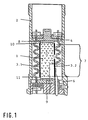
- an actuator body 1 which is in the form of a multilayer laminated laminate Layers of piezoelectric material and intervening metallic or electrically conductive, as Electrode layers has, with its front sides through (not designated) spring bands between a lower stationary metallic actuator base 6 and an upper, on the actuator head lying, axially movable metallic support plate. 4 elastically biased.
- the actuator body 1 is of a metallic actuator wall 2 included. The names “bottom” and “top” refer to the position of the actuator in the Drawing.
- the active area 7 is up and down each from one passive cover layer 8 and 9 limited. These passive Cover layers 8 and 9 serve initially for protection and electrical isolation and the demarcation of the active area 7 of the actuator body 1 with respect to the metallic support plate 4 and the likewise metallic actuator base 6.
- blind Electrodes 10, 11 introduced in the cover layers 8 and 9 .
- “Blind” in this case means that the electrodes do not go to any edge to the edge. They have thus no metallic contact with the common Outer electrodes 3.1 and 3.2, d. h., the electrical Properties remain unchanged.
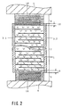
- FIG. 2 shows a preferred embodiment of a piezoelectric actuator, in both the upper Cover layer 8 as well as in the lower cover layer 9 at connect the active area 7 up and down, several blind electrodes 10, 11 in parallel at a distance lie to each other.
- the distance of the blind electrodes 10, 11 in the preferred embodiment is through the thickness the passive layers forming the cover layers 8, 9 Defined Pezokeramik füren.
- the layer thickness of the passive piezoceramic layers is in a real version for example 0.1mm. In this Case may be in the upper and lower cover layer 8, 9, for example, if they are 1.5mm thick, 14 blind Be inserted electrodes 10, 11.
- the layer thickness of the piezoelectric Layers in the active area 7 of the Actuator body 1 not necessarily with the layer thickness must match in the outer layers 8, 9, they are in Figure 2 shown differently. In the real case, however is used for the cost-effective production of a Multilayer actuator the layer thickness in the active area be identical to that in the cover layers 8, 9.
- FIG. 3 shows an advantageous variant of that in FIG. 2 shown embodiment, wherein in the field of passive Zones or outer layers 8, 9 outside an electrically conductive layer 14, the blind electrodes 10, 11 shorts, thereby increasing heat dissipation.
- Piezoelectric actuators designed according to the invention are in common rail diesel injector systems and in PDE injector systems are used. Also are Gasoline direct injection valves with such piezoelectric Actuators advantageous to realize.
Landscapes
- Fuel-Injection Apparatus (AREA)
Description
Bei einem solchen Vielschichtaktor beträgt die Schichtdicke des piezoelektrischen Materials zum Beispiel 0,1mm. Dann können in einer etwa 1,5mm Höhe betragenden oberen und unteren Deckschicht zum Beispiel 14 blinde Elektroden im Abstand von 0,1mm liegen.
- Figur 1
- zeigt im Längsschnitt einen Teil eines piezoelektrischen Aktormoduls, dessen Aktorkörper blinde Elektroden in seiner oberen und unteren Deckschicht aufweist.
- Figur 2
- zeigt in vergrößerter Darstellung eine bevorzugte Ausführungsform des erfindungsgemäßen piezoelektrischen Aktors mit mehreren parallel liegenden blinden Elektroden in der oberen und unteren Deckschicht.
- Figur 3
- eine variante der in Figur 2 dargestellten Ausführungsform.
Claims (6)
- Piezoelektrischer Aktor, insbesondere zur Betätigung von Steuerventilen oder Einspritzventilen an Verbrennungsmotoren in Kraftfahrzeugen, mit einem piezoelektrischen Aktorkörper (1) in Form eines vielschichtigen Laminats aus aufeinandergeschichteten Lagen piezoelektrischen Materials und dazwischenliegenden metallischen bzw. elektrisch leitenden, als Elektroden dienenden Schichten, wobei die als Elektroden dienenden Schichten durch gemeinsame Außenelektroden (3.1, 3.2) elektrisch miteinander verbunden sind, und wobei eine der Stirnseiten des Aktorkörpers (1) an einem ruhenden metallischen Aktorfuß (6) festgelegt ist und die andere Stirnseite an eine mit dem Aktorhub bewegliche metallische Halteplatte (4) angrenzt, dadurch gekennzeichnet, daß das piezoelektrische Material an beiden Stirnseiten blinde metallische Elektroden (10, 11) aufweist, die jeweils in einer passiven piezokeramischen Deckschicht (8, 9) zwischen der jeweiligen äußersten aktiven Piezokeramikschicht und der beweglichen Halteplatte (4) sowie dem Aktorfuß (6) liegen.
- Piezoelektrischer Aktor nach Anspruch 1, dadurch gekennzeichnet, daß in jeder passiven Deckschicht (8, 9) mehrere parallele blinde Elektroden (101-110, 111-119) im Abstand voneinander vorgesehen sind.
- Piezoelektrischer Aktor nach Anspruch 2, dadurch gekennzeichnet, daß die Abstände der blinden Elektroden jeweils gleich sind.
- Piezoelektrischer Aktor nach einem der Ansprüche 2 bis 3, dadurch gekennzeichnet, daß der gegenseitige Abstand der blinden Elektroden gleich oder kleiner als der Elektrodenabstand im aktiven Bereich ist
- Piezoelektrischer Aktor nach einem der vorangehenden Ansprüche, dadurch gekennzeichnet, daß die gemeinsame Elektroden (3.1 und 3.2) über die volle Länge des aktiven Bereichs (7) des Aktorkörpers hinausragen, so daß oben und unten ein Überlappungsbereich (12, 13) mit den passiven Deckschichten (8, 9) entsteht.
- Piezoelektrischer Aktor nach einem der vorangehenden Ansprüche, dadurch gekennzeichnet, daß die blinden metallischen Elektroden (10, 11) durch eine elektrisch leitende Schicht (14) kurzgeschlossen sind, so dass die Wärmeleitung zwischen den blinden Elektroden intensiviert wird, ohne dass die elektrische leitende Schicht (14) mit den Außenelektroden (3.1, 3.2) in Kontakt kommt.
Applications Claiming Priority (3)
| Application Number | Priority Date | Filing Date | Title |
|---|---|---|---|
| DE19856201A DE19856201A1 (de) | 1998-12-05 | 1998-12-05 | Piezoelektrischer Aktor |
| DE19856201 | 1998-12-05 | ||
| PCT/DE1999/002882 WO2000035027A1 (de) | 1998-12-05 | 1999-09-11 | Piezoelektrischer aktor |
Publications (3)
| Publication Number | Publication Date |
|---|---|
| EP1051761A1 EP1051761A1 (de) | 2000-11-15 |
| EP1051761B1 true EP1051761B1 (de) | 2005-11-09 |
| EP1051761B2 EP1051761B2 (de) | 2015-07-08 |
Family
ID=7890120
Family Applications (1)
| Application Number | Title | Priority Date | Filing Date |
|---|---|---|---|
| EP99973355.3A Expired - Lifetime EP1051761B2 (de) | 1998-12-05 | 1999-09-11 | Piezoelektrischer aktor |
Country Status (5)
| Country | Link |
|---|---|
| US (1) | US6291929B1 (de) |
| EP (1) | EP1051761B2 (de) |
| JP (1) | JP2002533041A (de) |
| DE (2) | DE19856201A1 (de) |
| WO (1) | WO2000035027A1 (de) |
Families Citing this family (22)
| Publication number | Priority date | Publication date | Assignee | Title |
|---|---|---|---|---|
| DE19928189A1 (de) * | 1999-06-19 | 2001-04-19 | Bosch Gmbh Robert | Piezoaktor |
| DE19928176A1 (de) * | 1999-06-19 | 2001-01-04 | Bosch Gmbh Robert | Piezoaktor |
| DE10002437A1 (de) * | 2000-01-21 | 2001-08-16 | Bosch Gmbh Robert | Piezoaktor |
| DE10025998A1 (de) * | 2000-05-25 | 2001-12-06 | Bosch Gmbh Robert | Piezoaktor |
| JP4356268B2 (ja) * | 2000-06-26 | 2009-11-04 | 株式会社デンソー | 燃料噴射装置 |
| DE10039424A1 (de) | 2000-08-11 | 2002-02-28 | Siemens Ag | Dosierventil mit einem hydraulischen Übertragungselement |
| DE10202574A1 (de) * | 2001-02-15 | 2002-09-12 | Ceramtec Ag | Piezokeramischer Vielschichtaktor mit einem Übergangsbereich zwischen dem aktiven Bereich und den inaktiven Kopf- und Fußbereichen |
| DE10136807A1 (de) * | 2001-07-27 | 2003-02-13 | Bosch Gmbh Robert | Brennstoffeinspritzventil |
| JP4697929B2 (ja) * | 2003-11-13 | 2011-06-08 | キヤノン株式会社 | 積層圧電素子及び振動波駆動装置 |
| US7077379B1 (en) | 2004-05-07 | 2006-07-18 | Brunswick Corporation | Fuel injector using two piezoelectric devices |
| DE102004031596A1 (de) * | 2004-06-30 | 2006-02-09 | Robert Bosch Gmbh | Piezoaktor |
| US7145282B2 (en) * | 2004-07-15 | 2006-12-05 | Delphi Technologies, Inc. | Actuator |
| DE112005001022B4 (de) * | 2005-01-06 | 2014-08-21 | Murata Manufacturing Co., Ltd. | Verfahren zur Herstellung eines piezoelektrischen Aktuators und piezoelektrischer Aktuator |
| DE102005063652B3 (de) | 2005-06-09 | 2020-06-04 | Tdk Electronics Ag | Piezoelektrisches Vielschichtbauelement |
| DE102005026717B4 (de) * | 2005-06-09 | 2016-09-15 | Epcos Ag | Piezoelektrisches Vielschichtbauelement |
| US7638928B2 (en) * | 2005-06-30 | 2009-12-29 | Intel Corporation | Piezo actuator for cooling |
| DE102008040769A1 (de) * | 2008-07-28 | 2010-02-04 | Robert Bosch Gmbh | Piezoaktor mit passiven Bereichen am Kopf und/oder Fuß |
| DE102009054629B4 (de) * | 2009-12-14 | 2015-01-15 | Semikron Elektronik Gmbh & Co. Kg | Piezotransformator |
| DE102010008775A1 (de) * | 2010-02-22 | 2011-08-25 | Epcos Ag, 81669 | Piezoelektrisches Vielschichtbauelement und Verfahren zur Herstellung eines piezoelektrischen Vielschichtbauelements |
| RU2447544C1 (ru) * | 2010-12-01 | 2012-04-10 | Федеральное государственное бюджетное образовательное учреждение высшего профессионального образования "Национальный исследовательский университет "МИЭТ" | Пьезоэлектрический прибор |
| WO2017171861A1 (en) * | 2016-04-01 | 2017-10-05 | Intel Corporation | Piezoelectric driven switches integrated in organic, flexible displays |
| DE102019110736B4 (de) * | 2019-04-25 | 2022-12-01 | Pi Ceramic Gmbh | Aktuator |
Family Cites Families (9)
| Publication number | Priority date | Publication date | Assignee | Title |
|---|---|---|---|---|
| DE3103061A1 (de) * | 1981-01-30 | 1982-08-05 | Daimler-Benz Ag, 7000 Stuttgart | "piezoelektrisches stellglied" |
| JPS6086880A (ja) * | 1983-10-19 | 1985-05-16 | Nec Corp | 電歪効果素子 |
| JPH04214686A (ja) * | 1990-10-05 | 1992-08-05 | Nec Corp | 電歪効果素子 |
| JPH04159785A (ja) * | 1990-10-23 | 1992-06-02 | Nec Corp | 電歪効果素子 |
| DE4201937C2 (de) * | 1991-01-25 | 1997-05-22 | Murata Manufacturing Co | Piezoelektrisches laminiertes Stellglied |
| US5168189A (en) * | 1991-09-18 | 1992-12-01 | Caterpillar Inc. | Solderless connector for a solid state motor stack |
| DE19613158A1 (de) * | 1996-04-02 | 1997-10-09 | Daetwyler Ag | Hochdynamischer piezoelektrischer Antrieb |
| DE19626671C1 (de) * | 1996-07-03 | 1997-10-16 | Fraunhofer Ges Forschung | Piezoelektrischer Leistungsaktor mit Kühlung und Verfahren zu seiner Herstellung |
| DE19650900A1 (de) * | 1996-12-07 | 1998-06-10 | Bosch Gmbh Robert | Piezoelektrischer Aktuator |
-
1998
- 1998-12-05 DE DE19856201A patent/DE19856201A1/de not_active Ceased
-
1999
- 1999-09-11 DE DE59912768T patent/DE59912768D1/de not_active Expired - Lifetime
- 1999-09-11 JP JP2000587390A patent/JP2002533041A/ja active Pending
- 1999-09-11 US US09/601,727 patent/US6291929B1/en not_active Expired - Fee Related
- 1999-09-11 EP EP99973355.3A patent/EP1051761B2/de not_active Expired - Lifetime
- 1999-09-11 WO PCT/DE1999/002882 patent/WO2000035027A1/de not_active Ceased
Also Published As
| Publication number | Publication date |
|---|---|
| WO2000035027A1 (de) | 2000-06-15 |
| DE19856201A1 (de) | 2000-06-15 |
| EP1051761B2 (de) | 2015-07-08 |
| EP1051761A1 (de) | 2000-11-15 |
| US6291929B1 (en) | 2001-09-18 |
| DE59912768D1 (de) | 2005-12-15 |
| JP2002533041A (ja) | 2002-10-02 |
Similar Documents
| Publication | Publication Date | Title |
|---|---|---|
| EP1051761B2 (de) | Piezoelektrischer aktor | |
| DE19857247C1 (de) | Piezoelektrischer Aktor | |
| EP1053423B1 (de) | Piezoelektrischer aktor | |
| EP1053425B1 (de) | Piezoelektrischer antrieb | |
| EP1053424A1 (de) | Piezoelektrischer aktor | |
| EP0770776A1 (de) | Servoventil für eine Einspritzdüse | |
| DE10245109A1 (de) | Injektor, insbesondere Kraftstoff-Einspritzventil, mit einem piezoelektrischen Aktor | |
| DE19849203A1 (de) | Brennstoffeinspritzventil | |
| EP0129020A1 (de) | Piezoelektrischer Steuerblock in Verbindung mit einer Kraftstoffeinspritzanlage | |
| DE102012100020A1 (de) | Kraftstoffeinspritzvorrichtung | |
| WO2001023746A1 (de) | Ventil zum steuern von flüssigkeiten | |
| DE10333696A1 (de) | Kraftstoffeinspritzvorrichtung | |
| DE19909451A1 (de) | Injektor mit einem Piezo-Mehrlagenaktor | |
| DE102016102890A1 (de) | Öl-Wasser-Wärmetauscher, insbesondere für den Verbrennungsmotor eines Kraftfahrzeuges | |
| EP1210516B1 (de) | Einspritzsystem und verfahren zum betreiben eines einspritzsystems | |
| DE10333697A1 (de) | Kraftstoffeinspritzvorrichtung | |
| EP3417673B1 (de) | Wärmetauschersystem | |
| DE102005014163B4 (de) | Piezoelektrische Aktoreinheit mit verbesserter Wärmeleitfähigkeit sowie Kraftstoffinjektor | |
| EP3036431B1 (de) | Piezoaktor für einen kraftstoffinjektor und kraftstoffinjektor | |
| DE102004050880B4 (de) | Kraftstoffinjektor mit Wärmetauscheinrichtung | |
| DE102010061946A1 (de) | Piezoelektrisches Aktormodul und Brennstoffeinspritzventil | |
| DE10333690A1 (de) | Kraftstoffeinspritzvorrichtung | |
| DE10333693B3 (de) | Kraftstoffeinspritzvorrichtung | |
| DE19643622A1 (de) | Kraftstoffeinspritzanlage für einen Verbrennungsmotor | |
| DE10333752A1 (de) | Kraftstoffeinspritzvorrichtung |
Legal Events
| Date | Code | Title | Description |
|---|---|---|---|
| PUAI | Public reference made under article 153(3) epc to a published international application that has entered the european phase |
Free format text: ORIGINAL CODE: 0009012 |
|
| AK | Designated contracting states |
Kind code of ref document: A1 Designated state(s): AT BE CH CY DE DK ES FI FR GB GR IE IT LI LU MC NL PT SE |
|
| AX | Request for extension of the european patent |
Free format text: AL;LT;LV;MK;RO;SI |
|
| 17P | Request for examination filed |
Effective date: 20001215 |
|
| 17Q | First examination report despatched |
Effective date: 20040112 |
|
| RBV | Designated contracting states (corrected) |
Designated state(s): DE FR GB IT |
|
| GRAP | Despatch of communication of intention to grant a patent |
Free format text: ORIGINAL CODE: EPIDOSNIGR1 |
|
| GRAS | Grant fee paid |
Free format text: ORIGINAL CODE: EPIDOSNIGR3 |
|
| GRAA | (expected) grant |
Free format text: ORIGINAL CODE: 0009210 |
|
| AK | Designated contracting states |
Kind code of ref document: B1 Designated state(s): DE FR GB IT |
|
| PG25 | Lapsed in a contracting state [announced via postgrant information from national office to epo] |
Ref country code: IT Free format text: LAPSE BECAUSE OF FAILURE TO SUBMIT A TRANSLATION OF THE DESCRIPTION OR TO PAY THE FEE WITHIN THE PRESCRIBED TIME-LIMIT;WARNING: LAPSES OF ITALIAN PATENTS WITH EFFECTIVE DATE BEFORE 2007 MAY HAVE OCCURRED AT ANY TIME BEFORE 2007. THE CORRECT EFFECTIVE DATE MAY BE DIFFERENT FROM THE ONE RECORDED. Effective date: 20051109 Ref country code: GB Free format text: LAPSE BECAUSE OF FAILURE TO SUBMIT A TRANSLATION OF THE DESCRIPTION OR TO PAY THE FEE WITHIN THE PRESCRIBED TIME-LIMIT Effective date: 20051109 |
|
| REG | Reference to a national code |
Ref country code: GB Ref legal event code: FG4D Free format text: NOT ENGLISH |
|
| REF | Corresponds to: |
Ref document number: 59912768 Country of ref document: DE Date of ref document: 20051215 Kind code of ref document: P |
|
| GBV | Gb: ep patent (uk) treated as always having been void in accordance with gb section 77(7)/1977 [no translation filed] |
Effective date: 20051109 |
|
| PLBI | Opposition filed |
Free format text: ORIGINAL CODE: 0009260 |
|
| 26 | Opposition filed |
Opponent name: SIEMENS AG Effective date: 20060808 |
|
| PLAX | Notice of opposition and request to file observation + time limit sent |
Free format text: ORIGINAL CODE: EPIDOSNOBS2 |
|
| PG25 | Lapsed in a contracting state [announced via postgrant information from national office to epo] |
Ref country code: FR Free format text: LAPSE BECAUSE OF FAILURE TO SUBMIT A TRANSLATION OF THE DESCRIPTION OR TO PAY THE FEE WITHIN THE PRESCRIBED TIME-LIMIT Effective date: 20061020 |
|
| EN | Fr: translation not filed | ||
| PLAF | Information modified related to communication of a notice of opposition and request to file observations + time limit |
Free format text: ORIGINAL CODE: EPIDOSCOBS2 |
|
| PLBB | Reply of patent proprietor to notice(s) of opposition received |
Free format text: ORIGINAL CODE: EPIDOSNOBS3 |
|
| PG25 | Lapsed in a contracting state [announced via postgrant information from national office to epo] |
Ref country code: FR Free format text: LAPSE BECAUSE OF FAILURE TO SUBMIT A TRANSLATION OF THE DESCRIPTION OR TO PAY THE FEE WITHIN THE PRESCRIBED TIME-LIMIT Effective date: 20051109 |
|
| RDAF | Communication despatched that patent is revoked |
Free format text: ORIGINAL CODE: EPIDOSNREV1 |
|
| APBM | Appeal reference recorded |
Free format text: ORIGINAL CODE: EPIDOSNREFNO |
|
| APBP | Date of receipt of notice of appeal recorded |
Free format text: ORIGINAL CODE: EPIDOSNNOA2O |
|
| APAH | Appeal reference modified |
Free format text: ORIGINAL CODE: EPIDOSCREFNO |
|
| APBQ | Date of receipt of statement of grounds of appeal recorded |
Free format text: ORIGINAL CODE: EPIDOSNNOA3O |
|
| PLAB | Opposition data, opponent's data or that of the opponent's representative modified |
Free format text: ORIGINAL CODE: 0009299OPPO |
|
| R26 | Opposition filed (corrected) |
Opponent name: SIEMENS AKTIENGESELLSCHAFT Effective date: 20060808 |
|
| APBU | Appeal procedure closed |
Free format text: ORIGINAL CODE: EPIDOSNNOA9O |
|
| PUAH | Patent maintained in amended form |
Free format text: ORIGINAL CODE: 0009272 |
|
| STAA | Information on the status of an ep patent application or granted ep patent |
Free format text: STATUS: PATENT MAINTAINED AS AMENDED |
|
| 27A | Patent maintained in amended form |
Effective date: 20150708 |
|
| AK | Designated contracting states |
Kind code of ref document: B2 Designated state(s): DE FR GB IT |
|
| REG | Reference to a national code |
Ref country code: DE Ref legal event code: R102 Ref document number: 59912768 Country of ref document: DE |
|
| PGFP | Annual fee paid to national office [announced via postgrant information from national office to epo] |
Ref country code: DE Payment date: 20181121 Year of fee payment: 20 |
|
| REG | Reference to a national code |
Ref country code: DE Ref legal event code: R071 Ref document number: 59912768 Country of ref document: DE |