EP1051984A2 - Aspirateur portable de secrétions nasales - Google Patents
Aspirateur portable de secrétions nasales Download PDFInfo
- Publication number
- EP1051984A2 EP1051984A2 EP99122336A EP99122336A EP1051984A2 EP 1051984 A2 EP1051984 A2 EP 1051984A2 EP 99122336 A EP99122336 A EP 99122336A EP 99122336 A EP99122336 A EP 99122336A EP 1051984 A2 EP1051984 A2 EP 1051984A2
- Authority
- EP
- European Patent Office
- Prior art keywords
- snivel
- air
- suction
- vacuum
- portable
- Prior art date
- Legal status (The legal status is an assumption and is not a legal conclusion. Google has not performed a legal analysis and makes no representation as to the accuracy of the status listed.)
- Withdrawn
Links
- 238000007789 sealing Methods 0.000 claims description 15
- 229920001971 elastomer Polymers 0.000 claims description 6
- 230000000712 assembly Effects 0.000 claims description 4
- 238000000429 assembly Methods 0.000 claims description 4
- 230000000903 blocking effect Effects 0.000 claims description 4
- 230000008602 contraction Effects 0.000 claims description 4
- 238000000034 method Methods 0.000 claims description 4
- 230000008569 process Effects 0.000 claims description 4
- 230000001131 transforming effect Effects 0.000 claims description 4
- 238000007599 discharging Methods 0.000 claims description 3
- 239000013013 elastic material Substances 0.000 claims 2
- 210000001331 nose Anatomy 0.000 abstract 2
- 230000005540 biological transmission Effects 0.000 description 7
- 230000008878 coupling Effects 0.000 description 5
- 238000010168 coupling process Methods 0.000 description 5
- 238000005859 coupling reaction Methods 0.000 description 5
- 239000000853 adhesive Substances 0.000 description 4
- 230000001070 adhesive effect Effects 0.000 description 4
- 238000003780 insertion Methods 0.000 description 3
- 230000037431 insertion Effects 0.000 description 3
- 230000008901 benefit Effects 0.000 description 2
- 238000010586 diagram Methods 0.000 description 2
- 230000009471 action Effects 0.000 description 1
- 230000015572 biosynthetic process Effects 0.000 description 1
- 230000003247 decreasing effect Effects 0.000 description 1
- 239000011796 hollow space material Substances 0.000 description 1
- 230000004941 influx Effects 0.000 description 1
- 238000009434 installation Methods 0.000 description 1
- 238000004519 manufacturing process Methods 0.000 description 1
- 230000004048 modification Effects 0.000 description 1
- 238000012986 modification Methods 0.000 description 1
- 229920002379 silicone rubber Polymers 0.000 description 1
- 239000007779 soft material Substances 0.000 description 1
Images


Classifications
-
- A—HUMAN NECESSITIES
- A61—MEDICAL OR VETERINARY SCIENCE; HYGIENE
- A61M—DEVICES FOR INTRODUCING MEDIA INTO, OR ONTO, THE BODY; DEVICES FOR TRANSDUCING BODY MEDIA OR FOR TAKING MEDIA FROM THE BODY; DEVICES FOR PRODUCING OR ENDING SLEEP OR STUPOR
- A61M1/00—Suction or pumping devices for medical purposes; Devices for carrying-off, for treatment of, or for carrying-over, body-liquids; Drainage systems
- A61M1/64—Containers with integrated suction means
- A61M1/67—Containers incorporating a piston-type member to create suction, e.g. syringes
-
- A—HUMAN NECESSITIES
- A61—MEDICAL OR VETERINARY SCIENCE; HYGIENE
- A61M—DEVICES FOR INTRODUCING MEDIA INTO, OR ONTO, THE BODY; DEVICES FOR TRANSDUCING BODY MEDIA OR FOR TAKING MEDIA FROM THE BODY; DEVICES FOR PRODUCING OR ENDING SLEEP OR STUPOR
- A61M1/00—Suction or pumping devices for medical purposes; Devices for carrying-off, for treatment of, or for carrying-over, body-liquids; Drainage systems
- A61M1/60—Containers for suction drainage, adapted to be used with an external suction source
-
- A—HUMAN NECESSITIES
- A61—MEDICAL OR VETERINARY SCIENCE; HYGIENE
- A61M—DEVICES FOR INTRODUCING MEDIA INTO, OR ONTO, THE BODY; DEVICES FOR TRANSDUCING BODY MEDIA OR FOR TAKING MEDIA FROM THE BODY; DEVICES FOR PRODUCING OR ENDING SLEEP OR STUPOR
- A61M1/00—Suction or pumping devices for medical purposes; Devices for carrying-off, for treatment of, or for carrying-over, body-liquids; Drainage systems
- A61M1/64—Containers with integrated suction means
- A61M1/65—Containers with integrated suction means the suction means being electrically actuated
-
- A—HUMAN NECESSITIES
- A61—MEDICAL OR VETERINARY SCIENCE; HYGIENE
- A61M—DEVICES FOR INTRODUCING MEDIA INTO, OR ONTO, THE BODY; DEVICES FOR TRANSDUCING BODY MEDIA OR FOR TAKING MEDIA FROM THE BODY; DEVICES FOR PRODUCING OR ENDING SLEEP OR STUPOR
- A61M1/00—Suction or pumping devices for medical purposes; Devices for carrying-off, for treatment of, or for carrying-over, body-liquids; Drainage systems
- A61M1/80—Suction pumps
- A61M1/81—Piston pumps, e.g. syringes
-
- A—HUMAN NECESSITIES
- A61—MEDICAL OR VETERINARY SCIENCE; HYGIENE
- A61M—DEVICES FOR INTRODUCING MEDIA INTO, OR ONTO, THE BODY; DEVICES FOR TRANSDUCING BODY MEDIA OR FOR TAKING MEDIA FROM THE BODY; DEVICES FOR PRODUCING OR ENDING SLEEP OR STUPOR
- A61M1/00—Suction or pumping devices for medical purposes; Devices for carrying-off, for treatment of, or for carrying-over, body-liquids; Drainage systems
- A61M1/80—Suction pumps
- A61M1/82—Membrane pumps, e.g. bulbs
-
- A—HUMAN NECESSITIES
- A61—MEDICAL OR VETERINARY SCIENCE; HYGIENE
- A61M—DEVICES FOR INTRODUCING MEDIA INTO, OR ONTO, THE BODY; DEVICES FOR TRANSDUCING BODY MEDIA OR FOR TAKING MEDIA FROM THE BODY; DEVICES FOR PRODUCING OR ENDING SLEEP OR STUPOR
- A61M1/00—Suction or pumping devices for medical purposes; Devices for carrying-off, for treatment of, or for carrying-over, body-liquids; Drainage systems
- A61M1/71—Suction drainage systems
- A61M1/74—Suction control
- A61M1/741—Suction control with means for varying suction manually
- A61M1/7413—Suction control with means for varying suction manually by changing the cross-section of the line
-
- A—HUMAN NECESSITIES
- A61—MEDICAL OR VETERINARY SCIENCE; HYGIENE
- A61M—DEVICES FOR INTRODUCING MEDIA INTO, OR ONTO, THE BODY; DEVICES FOR TRANSDUCING BODY MEDIA OR FOR TAKING MEDIA FROM THE BODY; DEVICES FOR PRODUCING OR ENDING SLEEP OR STUPOR
- A61M1/00—Suction or pumping devices for medical purposes; Devices for carrying-off, for treatment of, or for carrying-over, body-liquids; Drainage systems
- A61M1/71—Suction drainage systems
- A61M1/78—Means for preventing overflow or contamination of the pumping systems
-
- A—HUMAN NECESSITIES
- A61—MEDICAL OR VETERINARY SCIENCE; HYGIENE
- A61M—DEVICES FOR INTRODUCING MEDIA INTO, OR ONTO, THE BODY; DEVICES FOR TRANSDUCING BODY MEDIA OR FOR TAKING MEDIA FROM THE BODY; DEVICES FOR PRODUCING OR ENDING SLEEP OR STUPOR
- A61M2205/00—General characteristics of the apparatus
- A61M2205/82—Internal energy supply devices
- A61M2205/8206—Internal energy supply devices battery-operated
-
- A—HUMAN NECESSITIES
- A61—MEDICAL OR VETERINARY SCIENCE; HYGIENE
- A61M—DEVICES FOR INTRODUCING MEDIA INTO, OR ONTO, THE BODY; DEVICES FOR TRANSDUCING BODY MEDIA OR FOR TAKING MEDIA FROM THE BODY; DEVICES FOR PRODUCING OR ENDING SLEEP OR STUPOR
- A61M2210/00—Anatomical parts of the body
- A61M2210/06—Head
- A61M2210/0618—Nose
Definitions
- the present invention relates to a snivel inhaler, more particularly to a portable household motor-driven snivel inhaler for disposing of snivel from infants or patients.
- the present invention in order to solve the above problem provides a power-driven portable snivel inhaler that can be used with one hand under a constant vacuum, so that the inhaler has more improved convenience, efficiency, and safety.
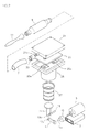
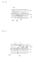
- FIG. 1 is an outlined view to illustrate an embodiment of the present invention
- FIG. 2 is an exploded perspective view showing inner parts of the present invention.
- the present invention has a case 1 where there is formed enough space accommodating a battery 3, an operating motor 5 connected to the battery, a power transmitting means that conveys the driving power of the motor 5, and a vacuum means where a vacuum is generated by the power transmitting means.
- a switch 13 for operating the motor 5 is also installed outside the case 1.
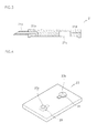
- the power transmitting means is designed with the following features:
- the first power transmitting member 17 is rotatably connected onto the outside circumference of the eccentric axis 15a.
- the first power transmitting member 17 is formed making a right angle with and spaced apart from the eccentric axis 15a.
- the first power transmitting member 17 has on the other end side thereof opposite to one end where the same is coupled to the eccentric axis 15a a first connection hole 17a through which the second power transmitting member 19 is coupled to the first conveying member 17.
- On one end of the second member 19 is formed a second connection hole 19a made such that the first connection hole 17a of the first power conveying member 17 is connected to a second connection hole 19a by means of a connection pin 18.
- the first and second connection holes 17a and 19a of the first and second power conveying members 17 and 19 are positioned so as to overlap and are fixed to each other by the connection pin 18.
- the power transmitting means connected to the motor 5 transforms the rotational movement of the motor 5 into the linear reciprocation movement.
- the other end of the second power transmission member 19 is formed to accomplish a proper connection with a length variable piston and the operation thereof.
- the above mentioned vacuum means comprises an air inhalation/exhalation tube member 21, a sealing member 23, a cylinder member 25, and a length variable piston 27.
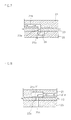
- the air inhalation/exhalation tube member 21 as shown in FIG. 3, is formed such that it protrudes from the case 1 having the first inhalation tube 21a wherethrough the air is inhaled.
- the second inhalation tube 21b is connected to the first inhalation tube 21a inside the air inhalation/exhalation tube member 21.
- the second inhalation tube 21b has an extended tube portion down the air inhalation/exhalation tube member 21 as illustrated in FIG. 3.
- the air inhalation/exhalation tube member 21 has a hollow space on one side of the second inhalation tube where a predetermined chamber 21c is made having an exhalation tube 21d connected to the outside of the air inhalation/exhalation tube member 21.
- the sealing member 23 as illustrated in FIG. 4, has respective holes 23a and 23b on the portions thereof respectively matching the predetermined chamber 21c connected with the second inhalation tube 21b and the exhalation tube 21d. These portions of sealing member 23 are tightly fixed to the air inhalation/exhalation tube member 21.
- the first and second opening/closing members 29 and 31 used as a check valve couple.
- the first and second opening/closing members 29 and 31 are preferably made such that they are large enough to cover their respective holes 23a and 23b and composed of a rubber-made elastic body having a disk shape, the first and second opening/closing members being connected to the sealing member 23 with an extended portion thereof as an adhesive, more preferably with an actual adhesive.
- the first and second opening/closing members 29 and 31 is designed such that when the air flows in through the air passage tube 7 toward the motor 5, the first opening/closing member hole 23a is opened and the second opening/closing member hole 23b is closed, and when the air is forced to flow from the motor 5 toward the air passage tube 5, the second opening/closing member hole 23b is opened, while the first opening/closing member hole 23a remains closed.
- the sealing member 31 for blocking the inflow of the outside air is made of silicon rubber.
- check valve according to the embodiment of the present invention is not confined to the above-mentioned description. Any check valve having a reversed structural installation for blocking an air inflow in one direction can be applied to the embodiments of the present invention.
- the cylinder member 25, whereupon the sealing member 23 and the air inhalation/exhalation tube member 21 are coupled, is formed with a flat faced end so that other parts can be fixed by additional coupling devices.
- the cylinder member 25 has a cylindrical member where a predetermined space is formed in the lower end side of the above flat rectangular shape (with reference to FIG. 2). Inside the cylinder member is a variable length piston 27 fixed by insertion.
- variable length piston 27 (with reference to FIG. 2) is coupled to the upper inner surface of the cylinder member 25 with an extra coupling member or an adhesive.
- the lower portion of the variable length piston 27 is also coupled to the upper portion of the above second power transmitting member 19 (with reference to FIG. 2) with an extra coupling member or an adhesive.
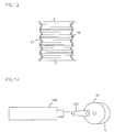
- the variable length cylinder 27 made of rubber is designed to expand and contract due to its bellows shaped formation.
- variable length piston 27 has on its inner circumference elastic members imposing elasticity onto its inner circumference (shown in FIG. 12).
- the elastic members are to help facilitate the expansion and contraction movement of the variable piston 27, preferably made of piano wire, fishing line, or elastic wire.
- One end of the air passage tube 7 is coupled by insertion on the outside circumference of the first inhalation tube 21a which is connected to the air inhalation/exhalation tube 21.
- an extra interface 33 may facilitate the connection.
- the air passage tube 7 is preferably made of an elastic rubber.
- the other end of the air passage tube 7 is coupled to the snivel storage pipe 9.
- the snivel storage pipe 9 has a predetermined volume for storing snivel, a vertical wall 7a in the air passage tube 7 (with reference to FIG. 1) and a passage hole 7b in an upper portion of this vertical wall 7a.
- the passage hole 7b is formed above the surface of the snivel to thus prevent the influx of snivel into the vacuum means and allow air alone to pass through it.
- a snivel guide member 11 is fixed by insertion to the other end of the above snivel storage pipe.
- the snivel guide member 11 is made in a tube shape and is preferably made of a soft material like rubber because it is directly put into the nose of infants and little children.
- a switch for driving the motor 5 is disposed outside the case 1 and the circuit diagram of its electrical connection is illustrated in FIG. 5.
- the switch is simply for conveying battery power to the motor selectively, and if necessary, an electric circuit may be modified using resistors.
- the motor 5 When the switch 13 is turned on after a user inserts into the nose of infants or little children an end portion of the snivel guide member 11, the motor 5 is run by battery power. And the eccentric cam 15 is rotated corresponding to the motor. The rotation movement of the eccentric cam 15 is turned into a linear reciprocation movement through the power transmitting member 17 according to the rotation of the eccentric cam 15. The driving power having a linear movement is transferred to the second power transmitting member 19.
- the second power transmitting member 19 provides a perpendicularly linear reciprocation movement.
- variable length piston 27 When the second power transmitting member 19 makes a downward movement, the variable length piston 27 also makes a downward movement as shown in FIG. 6. At this point, a vacuum is formed inside the variable length piston 27. Snivel in the nose of infants or little children is drawn into the snivel guide member 11 and stored in the snivel storage pipe 9. The snivel stored in the snivel storage pipe is not sent to the vacuum means but remains stored in the snivel storage pipe 9 due to the vertical wall 7a. Only air moves through the passage hole 7b along the arrow-marked direction of FIG. 6.
- the air is designed to move through the air passage tube 7 into the first inhalation tube 21a and the second inhalation tube 21b.
- the air as shown in FIG. 7, pushes the first opening/closing member 29 when passing through the hole 23a of the sealing member 23. And the air continues to make its way inside the variable length piston 27 through the cylinder member 25 to thus fill and expand the volume of the length variable piston 27.
- variable length piston as shown in FIG. 9, is compressed when the second power transmitting member 19 rises, the same returns to its initial position due to air pressure and the elastic power of the first opening/closing member 29, so that the hole 23a of the sealing member 23 is closed (shown in FIG. 10), and the second switching member 31 is pushed up by the air pressure (displayed in FIG. 11), with the result that the air moves along the exhalation tube 21d out into the atmosphere.
- snivel is disposed of through the repeated extension/contraction movements of the length variation cylinder 27.
- the snivel guide member 11 and the air passage tube 7 are made of rubber, discomfort to the user's nose is reduced, and the device can operate normally regardless of the variation of the case 1 and of the snivel guide member 11.
- FIG. 13 is a schematic view to illustrate the structure of a snivel inhaler according to the second embodiment of the present invention, which displays a case 1 having an inner space and forming an outer appearance, a battery 3, a motor 5, and a vacuum means mounted in the inner space of the case.
- the vacuum means comprises a pair of cylinders 100 for generating air pressure and the suction and exhaust valve assembly 102.
- a switch is installed outside the case 1 as was explained in the first embodiment and connected to the case by an electrical circuit formed to run the motor 5 according to a selective transmission of battery power.
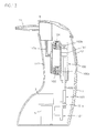
- the motor 5 has a disk-shaped rotating member 101 coupled to the axis of the motor.
- the rotating member 101 as shown in FIG. 14, is designed to rotate along with the rotating axis of the motor 5.
- an extended arm 101a preferably located at a point eccentric from the rotating center of the rotating member.
- a power transmission member 103 In the extended arm 101a is hinged one end of a power transmission member 103 for transforming a rotation movement of the rotating member 101 into a linear movement.
- the other end of the power transmission member 103 is hinged to a piston rod of the cylinder 100.
- the piston rod 105 is provided with a piston 107 reciprocating inside the cylinder 100 to thus make a vacuum.
- the cylinder 100 has first, and second vacuum ports 100a and 100b connected to the outside to form a vacuum.
- the first, and the second ports 100a and 100b are preferably disposed outside the stroke of the piston 107 (the movement distance from one end of the reciprocating movement of the piston to the other end thereof)
- the first and second ports 100a and 100b have on their inner circumferential surface a thread groove through which the first and second suction and exhaust valve assemblies 102 and 104 are connected.
- the first and second suction and exhaust valve assemblies 102 and 104 (for the sake of convenience, we take as an example only the first suction and exhaust valve assembly to explain our purpose), as shown in FIG. 15, comprises:
- the connector 109 is made such that one circumferential side of the same has a projected coupling part 109a of a screw thread pattern to which the first and second vacuum ports 100a, 100b are screwed and in the center of the connector is formed an axis-directed air passage 109b.
- the other end side opposite the coupling part 109a of the connector 109 has a predetermined spare space, and a screw thread screwed to the second suction and exhaust member 115 is formed on an outer circumference of the spare space. Since inner circumferential surface of the chamber of the connector 109 is formed in a tapered shape, the chamber 109c is still made when the first and second suction and exhaust members are connected. The chamber 109c is designed to facilitate air-flow.
- the first suction and exhaust member 111 has an air-inhalation hole 111a and an air-exhaust hole 111b and is made such that an outer circumferential surface thereof is formed in a tapered shape corresponding to the tapered part of the connector 109 and that the chamber 109c is secured when the first suction and exhaust member 111 is connected to the connector 109.
- the opening/closing member 113 is disposed on one side of the first suction and exhaust member 111 and has the first and second opening/closing parts 113a and 113b as shown in FIG. 16 and 17.
- the opening/closing part 113 is preferably made of an elastic rubber.
- One side of the first and second opening/closing parts 113a and 113b formed roughly in a circular shape are connected to the opening/closing member 113.
- the first opening/closing part 113a is preferably installed to have air exhaust hole 111b subject to selective opening/closing.
- the second suction and exhaust member 115 has the first suction and exhaust member 111 and the opening/closing member 113 inside the spare space and is designed such that a screw groove formed in the inner circumferential surface of the spare space is connected to the screw thread.
- the second suction and exhaust member 115 has an air inhalation hole 115a and an air exhaust hole 115b made to be inter-connected with the other end side of the spare space in order to let air pass through.
- the air inhalation hole 115a is made such that the second opening/closing part 113b of the opening/closing member 113, by contacting the air inhalation hole 115a, opens or closes selectively the air inhalation hole 115a.
- the first suction and exhaust valve assembly 102 and the second suction and exhaust valve assembly 104 having identical structures and disposed at each end of the cylinder 100 is structured such that the same 102 and 104 maintain a vacuum consecutively while the piston makes its reciprocation movement.
- the air passage 109b of the first suction and exhaust valve assembly 102 and the air passage of the second suction and exhaust valve assembly 104 are connected by a conduit 117, and a branch conduit 117a diverged from the conduit 117 is connected to the snivel storage pipe 9.
- the snivel storage pipe 9 according to the first embodiment is disposed in an outer side of the case 1, but the second embodiment has the snivel storage pipe 9 inside the case 1.
- the snivel storage pipe 9, as in the case of the first embodiment can be installed outside the case 1 and in other convenient locations.
- a rubber-made snivel guide member 11 In one side of the snivel storage pipe 9 is mounted a rubber-made snivel guide member 11, as in the case of the first embodiment.
- the battery 3 powered motor 5 rotates a rotating member 101 connected to the motor axis. Then a power transmission member 103, since one side thereof is hinged to an extended arm 101a of the rotating member 101, rotates according to rotation of the rotating member 101. And since the other end of the power transmission member 103 is hinged to the piston rod 105, the rotation movement of the rotating member 101 is changed into the linear movement and therefore, the piston 107 performs a reciprocation movement of a predetermined distance inside the cylinder 100.
- first suction and exhaust valve assembly 102 has the same structure as that of the second suction and exhaust valve assembly 104, an explanation based on the first suction and exhaust valve assembly 102 is made hereinafter.
- the compressed air held at the side of the first suction and exhaust valve assembly 102 of the cylinder 100 is discharged into the atmosphere through an air passage, the air exhaust hole 111b of the first suction member 111, the second suction and exhaust member 115, and then through the air exhaust hole 115b of the second suction and exhaust member 115.
- This discharge process is completed since, at the same time that the first opening/closing part 113a opened by the compressed air makes an connection with the air exhaust holes 111b and 115b, does the second opening/closing part 113b close the air opening/closing hole 115a by air pressure.
- snivel is inhaled by the vacuum formed inside the snivel storage pipe 9.
- the snivel storage pipe 9 holds only snivel and lets the air be carried through the conduit 117.
- the above mentioned first embodiment has one vacuum state during each stroke of the piston.
- the second embodiment of the present invention has two vacuum states during each stroke of the piston, snivel inhalation efficiency is greater than that of the first embodiment due to the more constantly maintained pressure inside the snivel storage pipe.
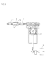
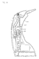
- FIG. 18 is a cross sectional view to illustrate a structure of a snivel inhaler according to a third embodiment of the present invention.
- a cylinder 301 has one open end and has thereinside a piston making reciprocating movements. And the other end of the cylinder 301, connected to a snivel storage pipe with a conduit to form a vacuum inside the snivel storage pipe, comprises an opening/closing valve and an air exhaust hole wherethrough the air held inside the cylinder is discharged according to the piston 303.
- the opening/closing valve has the same structure as that of the second embodiment, except that the second embodiment has formed vacuums consecutively due to a pair of opening/closing valves, while the third embodiment, provided with a single opening/closing valve, has a single vacuum generation during a stroke of the piston.
- the third embodiment which forms a vacuum with a single opening/closing valve can reduce a manufacturing price by decreasing the number of parts.
- the third embodiment has the snivel storage pipe 305 removably connected to the case 1.
- an indented portion 307 is formed at one side of the case 1, and then the snivel storage pipe 305 having a corresponding shape to the indented portion 307 is plastically molded, so that the indented portion 307 of the case 1 and the snivel storage pipe 305 are connected by a tight fit.
- the snivel storage pipe 305 has a hole connected to a vacuumed conduit, and the case also has a hole connected to a vacuumed conduit so that these two holes may be connected together.
- a temporary vacuum stopping means in which snivel inhalation, whenever necessary, is controlled by a vacuum.
- the temporary vacuum stopping means comprises a push-button 311 disposed in the case 1; a compressed coil spring 313 disposed inside the button 311 for returning the button 311 back to its initial location; and a hole stopper member 315 connected to the button 311 for selectively opening or closing a hole made in a vacuum conduit.
- the hole stopper member 315 disposed inside the vacuum conduit when the button 311 is pressed, connects the hole formed in the vacuum conduit to the atmosphere, and closes the hole of the vacuum conduit since the button returns to its initial location by the elasticity of the compressed coil spring 313 when the button is not pressed.
- FIG. 20 An extended snivel guide member means is illustrated in FIG. 20 in which the snivel storage pipe 305, instead of the snivel guide member, is connected to an extended vacuum conduit 321, which is connected with an auxiliary case 323 where an auxiliary snivel storage pipe 327 and the snivel guide member 11.
- auxiliary case 323 is also provided with another temporary vacuum stopping means having the same structure of the temporary vacuum stopping means of the above mentioned third embodiment. Since this temporary vacuum stopping means has the same structure and function as mentioned above, detailed description is replaced with the above explanation. The structure of the temporary vacuum stopping means may also be varied according to a user's preference.
- This extended snivel guide member means has an advantage over the first and second embodiments that a user can eliminate snivel at various locations holding only the extended portion while the main case stays at some predetermined place.
- the present invention is designed such that the same disposes of snivel from infants or little children with a vacuum formed in its motor-driven vacuum means.
- the present invention is portable and also usable with one hand, and it has improved safety and efficiency in disposing of snivel and can maintain a constant vacuum pressure due to an enhanced vacuum efficiency.
Landscapes
- Health & Medical Sciences (AREA)
- Heart & Thoracic Surgery (AREA)
- Vascular Medicine (AREA)
- Engineering & Computer Science (AREA)
- Anesthesiology (AREA)
- Biomedical Technology (AREA)
- Hematology (AREA)
- Life Sciences & Earth Sciences (AREA)
- Animal Behavior & Ethology (AREA)
- General Health & Medical Sciences (AREA)
- Public Health (AREA)
- Veterinary Medicine (AREA)
- Percussion Or Vibration Massage (AREA)
- External Artificial Organs (AREA)
Applications Claiming Priority (4)
| Application Number | Priority Date | Filing Date | Title |
|---|---|---|---|
| KR19990016980 | 1999-05-12 | ||
| KR9916980 | 1999-05-12 | ||
| KR1019990037191A KR100300441B1 (ko) | 1999-05-12 | 1999-09-02 | 휴대용 콧물 흡입기 |
| KR9937191 | 1999-09-02 |
Publications (2)
| Publication Number | Publication Date |
|---|---|
| EP1051984A2 true EP1051984A2 (fr) | 2000-11-15 |
| EP1051984A3 EP1051984A3 (fr) | 2001-08-22 |
Family
ID=26635119
Family Applications (1)
| Application Number | Title | Priority Date | Filing Date |
|---|---|---|---|
| EP99122336A Withdrawn EP1051984A3 (fr) | 1999-05-12 | 1999-11-09 | Aspirateur portable de secrétions nasales |
Country Status (5)
| Country | Link |
|---|---|
| EP (1) | EP1051984A3 (fr) |
| JP (1) | JP2000325466A (fr) |
| CN (1) | CN1273863A (fr) |
| CA (1) | CA2288455A1 (fr) |
| HK (1) | HK1021482A2 (fr) |
Cited By (16)
| Publication number | Priority date | Publication date | Assignee | Title |
|---|---|---|---|---|
| US6907879B2 (en) | 2002-02-04 | 2005-06-21 | Ndt | Agent delivery and aspiration device |
| FR2877579A1 (fr) * | 2004-11-09 | 2006-05-12 | Jose Bensoussan | Dispositif d'aspiration de secretions nasales |
| WO2009060111A1 (fr) * | 2007-11-08 | 2009-05-14 | Italfarmaco, S.A. | Embout d'aspiration et aspirateur de sécrétions nasales pour bébé équipé d'un dispositif de protection contre la contamination et la transmission de germes pathogènes |
| US8070744B1 (en) * | 2008-02-01 | 2011-12-06 | Clements Clara C | Nasal aspiration device |
| CN103211700A (zh) * | 2013-04-25 | 2013-07-24 | 余鸿桦 | 一种自带动力鼻腔冲洗器 |
| WO2016184918A1 (fr) * | 2015-05-18 | 2016-11-24 | Smith & Nephew Plc | Systèmes de pompe thermo-assistés pour utilisation dans le traitement des plaies par pression négative |
| US10183112B2 (en) | 2013-08-30 | 2019-01-22 | Hollister Incorporated | Device for trans anal irrigation |
| US10598163B2 (en) | 2015-12-08 | 2020-03-24 | Koninklijke Philips N.V. | Semi-free rotating crankshaft actuator to pre-stress and fast release a spring loadable plunger for an oral healthcare appliance |
| US10737013B2 (en) | 2014-07-08 | 2020-08-11 | Hollister Incorporated | Portable trans anal irrigation device |
| US10765796B2 (en) | 2014-07-08 | 2020-09-08 | Hollister Incorporated | Trans anal irrigation platform with bed module |
| US11040156B2 (en) | 2015-07-20 | 2021-06-22 | Pearl Therapeutics, Inc. | Aerosol delivery systems |
| US11383021B2 (en) | 2016-07-08 | 2022-07-12 | Hollister Incorporated | Wireless electronic pump design for a body cavity irrigation device |
| CN115317680A (zh) * | 2022-07-15 | 2022-11-11 | 广州艾渼智能科技有限公司 | 一种防回流吸鼻器 |
| US11497844B2 (en) | 2016-12-14 | 2022-11-15 | Hollister Incorporated | Transanal irrigation device and system |
| US11577018B2 (en) | 2016-07-08 | 2023-02-14 | Hollister Incorporated | Body cavity irrigation integrated manual controller and pump device, system and method |
| US11596422B2 (en) | 2016-11-03 | 2023-03-07 | Hollister Incorporated | Adjustable bowel treatment arm |
Families Citing this family (13)
| Publication number | Priority date | Publication date | Assignee | Title |
|---|---|---|---|---|
| KR100360605B1 (ko) * | 2000-08-17 | 2002-11-18 | 주식회사 지인텍 | 의료기기 |
| US8025173B2 (en) * | 2006-09-07 | 2011-09-27 | Allegiance Corporation | Collapsible canister liner for medical fluid collection |
| JP5274062B2 (ja) * | 2008-03-17 | 2013-08-28 | 株式会社 エピア | 簡易型便吸引器具 |
| CN103877629B (zh) * | 2014-04-15 | 2015-10-21 | 江西理工大学 | 擤鼻涕消音罩 |
| WO2015166749A1 (fr) | 2014-04-30 | 2015-11-05 | 株式会社村田製作所 | Dispositif d'aspiration |
| JP6053718B2 (ja) * | 2014-05-13 | 2016-12-27 | 柳瀬ワイチ株式会社 | 体液吸引器 |
| CN105877995A (zh) * | 2014-10-08 | 2016-08-24 | 丽水学院 | 手持脉动可控式洗鼻器 |
| CN109106585B (zh) * | 2018-10-26 | 2021-03-09 | 青岛大学附属医院 | 一种鼻腔冲洗器 |
| CN109481284A (zh) * | 2018-12-27 | 2019-03-19 | 凌春雨 | 一种用于儿科临床的鼻腔清洗装置 |
| CN109876207B (zh) * | 2019-04-06 | 2021-07-06 | 河南科技大学第一附属医院 | 一种医用泌尿外科导尿护理设备 |
| CN110025839B (zh) * | 2019-05-31 | 2021-04-30 | 青岛市市立医院 | 一种急诊科吸痰装置 |
| CN114788902A (zh) * | 2022-04-15 | 2022-07-26 | 东莞市茗创优尚电子科技有限公司 | 一种吸鼻器 |
| CN115671412A (zh) * | 2022-07-27 | 2023-02-03 | 丽水市华荟科技有限公司 | 一种吸鼻器 |
Family Cites Families (4)
| Publication number | Priority date | Publication date | Assignee | Title |
|---|---|---|---|---|
| US5098386A (en) * | 1991-05-17 | 1992-03-24 | Smith Ina L | Infant nasal suction apparatus |
| FR2706775A1 (en) * | 1993-06-23 | 1994-12-30 | Achard Michel | Tip intended for an apparatus for dispensing and/or sampling a fluid substance, in particular in the medical field, and apparatus allowing its implementation |
| US5645540A (en) * | 1994-10-11 | 1997-07-08 | Stryker Corporation | Blood conservation system |
| FR2769229B1 (fr) * | 1997-10-07 | 1999-11-19 | Philippe Lavaud | Dispositif mouche nez pour bebe |
-
1999
- 1999-11-04 CA CA 2288455 patent/CA2288455A1/fr not_active Abandoned
- 1999-11-05 JP JP31469899A patent/JP2000325466A/ja active Pending
- 1999-11-09 EP EP99122336A patent/EP1051984A3/fr not_active Withdrawn
- 1999-11-10 CN CN99122292A patent/CN1273863A/zh active Pending
- 1999-12-09 HK HK99105769A patent/HK1021482A2/xx not_active IP Right Cessation
Non-Patent Citations (1)
| Title |
|---|
| None |
Cited By (23)
| Publication number | Priority date | Publication date | Assignee | Title |
|---|---|---|---|---|
| US6907879B2 (en) | 2002-02-04 | 2005-06-21 | Ndt | Agent delivery and aspiration device |
| FR2877579A1 (fr) * | 2004-11-09 | 2006-05-12 | Jose Bensoussan | Dispositif d'aspiration de secretions nasales |
| WO2006051206A1 (fr) * | 2004-11-09 | 2006-05-18 | Ubimed L.L.C. | Dispositif d'aspiration de sécrétions nasales |
| WO2009060111A1 (fr) * | 2007-11-08 | 2009-05-14 | Italfarmaco, S.A. | Embout d'aspiration et aspirateur de sécrétions nasales pour bébé équipé d'un dispositif de protection contre la contamination et la transmission de germes pathogènes |
| US8070744B1 (en) * | 2008-02-01 | 2011-12-06 | Clements Clara C | Nasal aspiration device |
| CN103211700A (zh) * | 2013-04-25 | 2013-07-24 | 余鸿桦 | 一种自带动力鼻腔冲洗器 |
| CN103211700B (zh) * | 2013-04-25 | 2014-12-03 | 余鸿桦 | 一种自带动力鼻腔冲洗器 |
| US11116891B2 (en) | 2013-08-30 | 2021-09-14 | Hollister Incorporated | Device for trans anal irrigation |
| US10183112B2 (en) | 2013-08-30 | 2019-01-22 | Hollister Incorporated | Device for trans anal irrigation |
| US10737013B2 (en) | 2014-07-08 | 2020-08-11 | Hollister Incorporated | Portable trans anal irrigation device |
| US11497845B2 (en) | 2014-07-08 | 2022-11-15 | Hollister Incorporated | Trans anal irrigation platform with bed module |
| US10765796B2 (en) | 2014-07-08 | 2020-09-08 | Hollister Incorporated | Trans anal irrigation platform with bed module |
| US11071653B2 (en) | 2015-05-18 | 2021-07-27 | Smith & Nephew Plc | Heat-assisted pumping systems for use in negative pressure wound therapy |
| WO2016184918A1 (fr) * | 2015-05-18 | 2016-11-24 | Smith & Nephew Plc | Systèmes de pompe thermo-assistés pour utilisation dans le traitement des plaies par pression négative |
| US12186166B2 (en) | 2015-05-18 | 2025-01-07 | Smith & Nephew Plc | Heat-assisted pumping systems for use in negative pressure wound therapy |
| US11040156B2 (en) | 2015-07-20 | 2021-06-22 | Pearl Therapeutics, Inc. | Aerosol delivery systems |
| US12151061B2 (en) | 2015-07-20 | 2024-11-26 | Pearl Therapeutics, Inc. | Aerosol delivery systems and related methods |
| US10598163B2 (en) | 2015-12-08 | 2020-03-24 | Koninklijke Philips N.V. | Semi-free rotating crankshaft actuator to pre-stress and fast release a spring loadable plunger for an oral healthcare appliance |
| US11577018B2 (en) | 2016-07-08 | 2023-02-14 | Hollister Incorporated | Body cavity irrigation integrated manual controller and pump device, system and method |
| US11383021B2 (en) | 2016-07-08 | 2022-07-12 | Hollister Incorporated | Wireless electronic pump design for a body cavity irrigation device |
| US11596422B2 (en) | 2016-11-03 | 2023-03-07 | Hollister Incorporated | Adjustable bowel treatment arm |
| US11497844B2 (en) | 2016-12-14 | 2022-11-15 | Hollister Incorporated | Transanal irrigation device and system |
| CN115317680A (zh) * | 2022-07-15 | 2022-11-11 | 广州艾渼智能科技有限公司 | 一种防回流吸鼻器 |
Also Published As
| Publication number | Publication date |
|---|---|
| EP1051984A3 (fr) | 2001-08-22 |
| CA2288455A1 (fr) | 2000-11-12 |
| CN1273863A (zh) | 2000-11-22 |
| JP2000325466A (ja) | 2000-11-28 |
| HK1021482A2 (en) | 2000-06-02 |
Similar Documents
| Publication | Publication Date | Title |
|---|---|---|
| EP1051984A2 (fr) | Aspirateur portable de secrétions nasales | |
| KR100611875B1 (ko) | 피부 관리기 | |
| US5304129A (en) | Pivotable foot operated breast pump | |
| US7569031B2 (en) | Breast pump | |
| JP2005161009A (ja) | 掃除機の屈折延長管 | |
| KR20010093070A (ko) | 전기 진공 청소기 | |
| US20030176817A1 (en) | Electrical multi-functional fitness and body slimming massage device | |
| JP2005125065A (ja) | 掃除機の屈折延長管 | |
| JP2005161010A (ja) | 真空掃除機の屈折延長管 | |
| KR20000068899A (ko) | 정확성이 높은 연동 펌프 | |
| CN221195441U (zh) | 双向气泵 | |
| US6248059B1 (en) | Powered external vacuum appliance for the treatment of impotence | |
| US20230157500A1 (en) | Cleaning device having vacuum cleaner and dust collecting station | |
| JPH10227288A (ja) | 両方向緊密シールを備えた容積ポンプ | |
| KR100300441B1 (ko) | 휴대용 콧물 흡입기 | |
| KR200170796Y1 (ko) | 휴대용 콧물 흡입기 | |
| EP1559359A3 (fr) | Aspirateur | |
| JP2002537021A (ja) | ポンプを有し且つこのポンプの領域に騒音減少手段を設けた真空マッサージ装置 | |
| CN220860048U (zh) | 内镜用吸引阀门和内窥镜 | |
| JP3599093B2 (ja) | 内視鏡の送気送水バルブ構造 | |
| CN1329001C (zh) | 抽吸软管组件和具有其的真空吸尘器 | |
| JP3023725U (ja) | エアーポンプとその接続具 | |
| TW474878B (en) | A hand-held suction pump | |
| CN217724015U (zh) | 弹性拉杆结构及牙科治疗机 | |
| CN109847117A (zh) | 一种手动吸痰器 |
Legal Events
| Date | Code | Title | Description |
|---|---|---|---|
| PUAI | Public reference made under article 153(3) epc to a published international application that has entered the european phase |
Free format text: ORIGINAL CODE: 0009012 |
|
| AK | Designated contracting states |
Kind code of ref document: A2 Designated state(s): AT BE CH CY DE DK ES FI FR GB GR IE IT LI LU MC NL PT SE |
|
| AX | Request for extension of the european patent |
Free format text: AL;LT;LV;MK;RO;SI |
|
| PUAL | Search report despatched |
Free format text: ORIGINAL CODE: 0009013 |
|
| AK | Designated contracting states |
Kind code of ref document: A3 Designated state(s): AT BE CH CY DE DK ES FI FR GB GR IE IT LI LU MC NL PT SE |
|
| AX | Request for extension of the european patent |
Free format text: AL;LT;LV;MK;RO;SI |
|
| AKX | Designation fees paid | ||
| REG | Reference to a national code |
Ref country code: DE Ref legal event code: 8566 |
|
| STAA | Information on the status of an ep patent application or granted ep patent |
Free format text: STATUS: THE APPLICATION IS DEEMED TO BE WITHDRAWN |
|
| 18D | Application deemed to be withdrawn |
Effective date: 20020223 |