EP1052033A1 - System de palier pour cylindres de travail - Google Patents
System de palier pour cylindres de travail Download PDFInfo
- Publication number
- EP1052033A1 EP1052033A1 EP99105915A EP99105915A EP1052033A1 EP 1052033 A1 EP1052033 A1 EP 1052033A1 EP 99105915 A EP99105915 A EP 99105915A EP 99105915 A EP99105915 A EP 99105915A EP 1052033 A1 EP1052033 A1 EP 1052033A1
- Authority
- EP
- European Patent Office
- Prior art keywords
- bearing
- forces
- bearings
- roller
- roll
- Prior art date
- Legal status (The legal status is an assumption and is not a legal conclusion. Google has not performed a legal analysis and makes no representation as to the accuracy of the status listed.)
- Withdrawn
Links
- 238000005096 rolling process Methods 0.000 claims abstract description 9
- 238000010276 construction Methods 0.000 description 3
- 101100139852 Danio rerio radil gene Proteins 0.000 description 1
- 101100139854 Mus musculus Radil gene Proteins 0.000 description 1
- 238000009434 installation Methods 0.000 description 1
- 239000000463 material Substances 0.000 description 1
- 239000002184 metal Substances 0.000 description 1
- 238000007789 sealing Methods 0.000 description 1
Images
Classifications
-
- B—PERFORMING OPERATIONS; TRANSPORTING
- B21—MECHANICAL METAL-WORKING WITHOUT ESSENTIALLY REMOVING MATERIAL; PUNCHING METAL
- B21B—ROLLING OF METAL
- B21B31/00—Rolling stand structures; Mounting, adjusting, or interchanging rolls, roll mountings, or stand frames
- B21B31/07—Adaptation of roll neck bearings
-
- B—PERFORMING OPERATIONS; TRANSPORTING
- B21—MECHANICAL METAL-WORKING WITHOUT ESSENTIALLY REMOVING MATERIAL; PUNCHING METAL
- B21B—ROLLING OF METAL
- B21B31/00—Rolling stand structures; Mounting, adjusting, or interchanging rolls, roll mountings, or stand frames
- B21B31/02—Rolling stand frames or housings; Roll mountings ; Roll chocks
-
- B—PERFORMING OPERATIONS; TRANSPORTING
- B21—MECHANICAL METAL-WORKING WITHOUT ESSENTIALLY REMOVING MATERIAL; PUNCHING METAL
- B21B—ROLLING OF METAL
- B21B13/00—Metal-rolling stands, i.e. an assembly composed of a stand frame, rolls, and accessories
- B21B13/14—Metal-rolling stands, i.e. an assembly composed of a stand frame, rolls, and accessories having counter-pressure devices acting on rolls to inhibit deflection of same under load; Back-up rolls
- B21B13/147—Cluster mills, e.g. Sendzimir mills, Rohn mills, i.e. each work roll being supported by two rolls only arranged symmetrically with respect to the plane passing through the working rolls
Definitions
- the invention relates to a work roll storage, especially for multi-roll mill stands.
- a particular problem is that of diameter very small work rolls acting axial forces.
- rollers are each executed with two pins and two bearings, also here the possible bearing diameters by the minimum possible work roll diameters are limited.
- the invention has for its object a storage especially for the smallest work rolls with the maximum possible transferable Axial forces and thus acceptable service life and to show usable operating conditions.
- the bearings are arranged opposite one another, e.g. on the Drive side of the roll stand below and on the operating side above.
- bearing bushes fully equipped with bearings and seals can be attached to the peg with a wide variety of components become.
- the bearing bushes in turn are e.g. for the lower roller the drive-side door and for the upper work roll on the operator door locked.
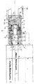
- the one ends are assigned to each other in particular two thin strips for rolling together Metal interacting work rolls 1 (upper work roll) and 2 (lower work roll).
- Storage at the other ends of the work rolls 1, 2 correspond to that shown Storage with the proviso that there the lower bearing roller 2 is stored as in the drawing, the storage of upper work roll 1 is shown and that there the storage the work roll 1 takes place as in the drawing Storage of the lower work roll 2 is shown.
- the upper Work roll 1 is thus only shown at the end shown "Flying” stored, and the lower work roll 2 only “flying” at the other end, as in the drawing the upper work roll 1 on its one, shown End “on the fly” is stored.
- the upper work roll 1 is included a coaxial bearing journal 3 smaller diameter in one piece provided, which in turn consists of two sections, an inner section 3a, the diameter of which is slightly smaller is called the diameter of the work roll itself and an outer one Section 3b with a significantly smaller diameter.
- This Bearing pin 3 is in the area of section 3a with interposition of a needle bearing 4 absorbing radil forces rotatably supported in a bearing bush 5.
- a head part 5a of the Bearing bush 5 encloses an annular chamber 6, which leads to the work roll 1 is sealed by a sealing ring 7 without to hinder the rotation of the pin 3 in the bearing bush 5.
- a sleeve-shaped bearing bush part 5b Connects to the head part 5a of the bearing bush 5 the end facing away from the work roll 1 is a sleeve-shaped bearing bush part 5b, whose outer diameter is that of the head part 5a is the same, but the inside diameter is significantly larger is than that of the head part 5a and is also significantly larger than the inner diameter of the annular chamber 6 that the needle bearing 4 records. Due to the jump in diameter from the inside diameter of the head part 5a to the inner diameter of the sleeve-shaped Bearing bush part 5b creates an annular shoulder surface 5c, on which a double-row roller bearing 8 with an inner Cage 9 is present.
- the roller bearing 8 designed as a double-row ball bearing, which absorbs axial forces from the upper work roll 1 regardless of the longitudinal direction of the roller 1 the axial forces act.
- the middle cage 13 lies axially playlessly between the shoulder 19 between the trunnion sections 3a and 3b of the journal 3 and the end face of one sleeve 20 pushed onto section 3b.
- the outer cage 14 of the rolling bearing 8 is based on several, on the circumference distributed, axially variable in length Coil springs 15 in a cylindrical bearing body 16 near its inner end, the one at its outer end an annular groove 17 engages over a fixed bearing flange 18 and is rotatably connected to the bearing bush 5.
- the radial bearing 4 corresponding radial bearing 4a near the outer end of the bearing pin 3, and it is the thrust bearing 8th arranged symmetrically between the two radial bearings 4, 4a
- the second radial bearing 4a lies in an annular groove 16a of the bearing body 16 and is based on the bottom of this annular groove 16a and from the outer wall of the bush 20, the outer diameter of the outer diameter corresponds to the journal section 3a, so that the two radial bearings 4, 4a have the same inside and outside diameters to have.
- the lower work roll 2 ends with its smooth radial End face while maintaining axial play in one plane, in which the upper work roll 1 merges into the journal 3.
- the two work rolls work immediately together, as a rule, however there is an adjustable gap between them through which the strip material to be processed by means of the rollers is passed through becomes.
Landscapes
- Engineering & Computer Science (AREA)
- Mechanical Engineering (AREA)
- Rolls And Other Rotary Bodies (AREA)
- Rolling Contact Bearings (AREA)
Applications Claiming Priority (2)
| Application Number | Priority Date | Filing Date | Title |
|---|---|---|---|
| DE19913102 | 1999-03-23 | ||
| DE19913102 | 1999-03-23 |
Publications (1)
| Publication Number | Publication Date |
|---|---|
| EP1052033A1 true EP1052033A1 (fr) | 2000-11-15 |
Family
ID=7902103
Family Applications (1)
| Application Number | Title | Priority Date | Filing Date |
|---|---|---|---|
| EP99105915A Withdrawn EP1052033A1 (fr) | 1999-03-23 | 1999-03-24 | System de palier pour cylindres de travail |
Country Status (1)
| Country | Link |
|---|---|
| EP (1) | EP1052033A1 (fr) |
Citations (8)
| Publication number | Priority date | Publication date | Assignee | Title |
|---|---|---|---|---|
| DE405911C (de) * | 1924-11-13 | Fried Krupp Akt Ges Grusonwerk | Rollen- oder Kugellageranordnung fuer die Zapfen von Walzen bei Walzwerken | |
| DE421732C (de) * | 1924-04-29 | 1925-11-17 | Karl Peter Dr Ing | Lageranordnung fuer Walzwerke |
| US1772248A (en) * | 1927-08-03 | 1930-08-05 | Charles J Gibbons | Rolling mill |
| FR728240A (fr) * | 1930-12-20 | 1932-07-02 | Witkowitzer Bergb Gewerkschaft | Laminoir avec cylindres de travail soutenus totalement ou partiellement sur la longueur de la table |
| US1903724A (en) * | 1930-07-29 | 1933-04-11 | Rohn Wilhelm | Multihigh rolling mechanism |
| JPS5435160A (en) * | 1977-08-24 | 1979-03-15 | Ishikawajima Harima Heavy Ind Co Ltd | Rolling mill |
| JPS5823507A (ja) * | 1981-08-07 | 1983-02-12 | Hitachi Ltd | 圧延機用ロ−ル軸受 |
| EP0637695A1 (fr) * | 1993-08-06 | 1995-02-08 | SKF Industrial Trading & Development Company, B.V. | Agencement de palier, roulement à rouleaux pour usage dans cet agencement et procédé de fabrication d'un élément de cet agencement |
-
1999
- 1999-03-24 EP EP99105915A patent/EP1052033A1/fr not_active Withdrawn
Patent Citations (8)
| Publication number | Priority date | Publication date | Assignee | Title |
|---|---|---|---|---|
| DE405911C (de) * | 1924-11-13 | Fried Krupp Akt Ges Grusonwerk | Rollen- oder Kugellageranordnung fuer die Zapfen von Walzen bei Walzwerken | |
| DE421732C (de) * | 1924-04-29 | 1925-11-17 | Karl Peter Dr Ing | Lageranordnung fuer Walzwerke |
| US1772248A (en) * | 1927-08-03 | 1930-08-05 | Charles J Gibbons | Rolling mill |
| US1903724A (en) * | 1930-07-29 | 1933-04-11 | Rohn Wilhelm | Multihigh rolling mechanism |
| FR728240A (fr) * | 1930-12-20 | 1932-07-02 | Witkowitzer Bergb Gewerkschaft | Laminoir avec cylindres de travail soutenus totalement ou partiellement sur la longueur de la table |
| JPS5435160A (en) * | 1977-08-24 | 1979-03-15 | Ishikawajima Harima Heavy Ind Co Ltd | Rolling mill |
| JPS5823507A (ja) * | 1981-08-07 | 1983-02-12 | Hitachi Ltd | 圧延機用ロ−ル軸受 |
| EP0637695A1 (fr) * | 1993-08-06 | 1995-02-08 | SKF Industrial Trading & Development Company, B.V. | Agencement de palier, roulement à rouleaux pour usage dans cet agencement et procédé de fabrication d'un élément de cet agencement |
Non-Patent Citations (2)
| Title |
|---|
| PATENT ABSTRACTS OF JAPAN vol. 003, no. 059 (C - 046) 19 May 1979 (1979-05-19) * |
| PATENT ABSTRACTS OF JAPAN vol. 007, no. 102 (M - 211) 30 April 1983 (1983-04-30) * |
Similar Documents
| Publication | Publication Date | Title |
|---|---|---|
| EP1425516B1 (fr) | Systeme de palier pour cylindres, rouleaux ou tambours | |
| WO2007147386A2 (fr) | Palier à roulement à inclinaison réglable | |
| DE3942612C2 (de) | Offenend-Spinnvorrichtung | |
| EP0205800A2 (fr) | Fixation de bagues de roulements | |
| EP0157017A1 (fr) | Arrangement de supports pour têtes magnétiques d'une unité de disque magnétique | |
| DE19511943C2 (de) | Vorrichtung zum kontinuierlichen Beschichten von Metallband | |
| CH697797B1 (de) | Streckwerk für Textilfaserbänder. | |
| DE3607729C2 (fr) | ||
| DE1575381A1 (de) | Lagerung und Antrieb fuer eine Walze mit steuerbarer Balligkeit | |
| DE3644204C2 (fr) | ||
| DE19603652C2 (de) | Durchbiegungseinstellwalze | |
| EP0422413B1 (fr) | Broche avec un palier en deux parties | |
| EP0548305B1 (fr) | Tete de guidage pour cylindres bobineurs lourds | |
| DE102009023741A1 (de) | Drehdurchführung | |
| EP1239170A1 (fr) | Rouleau à auto-réglage de la flexion | |
| DE69303519T2 (de) | Kopflageraufbau zum drehenden Abstützen von Wellen und dergleichen | |
| EP1006235B1 (fr) | Palier pour rouleau | |
| DE10144974B4 (de) | Walzgerüst zum Walzen von stab- oder rohrförmigem Gut | |
| DE3931232C2 (de) | Lageranordnung für die Kopftrommel eines Magnetbandgeräts | |
| DE29920839U1 (de) | Lagersystem für Zapfen von Zapfenkreuzen und Kreuzgelenkanordnung | |
| DE10058272B4 (de) | Walze einer Arbeitsmaschine | |
| EP3562999B1 (fr) | Dispositif pour déplacer une lame d'aiguille d'un aiguillage | |
| DE4033753C1 (fr) | ||
| DE19953370C1 (de) | Lagerung für eine Walze, insbesondere für die Druckwalze in einer Druckmaschine | |
| DE2229686C3 (de) | Axiallager für Arbeitswalzen von Mehrwalzengerüsten |
Legal Events
| Date | Code | Title | Description |
|---|---|---|---|
| PUAI | Public reference made under article 153(3) epc to a published international application that has entered the european phase |
Free format text: ORIGINAL CODE: 0009012 |
|
| AK | Designated contracting states |
Kind code of ref document: A1 Designated state(s): DE FI FR GB IT SE |
|
| AX | Request for extension of the european patent |
Free format text: AL;LT;LV;MK;RO;SI |
|
| RIN1 | Information on inventor provided before grant (corrected) |
Inventor name: SONDERMANN, JUERGEN |
|
| 17P | Request for examination filed |
Effective date: 20010514 |
|
| AKX | Designation fees paid |
Free format text: DE FI FR GB IT SE |
|
| 17Q | First examination report despatched |
Effective date: 20020521 |
|
| STAA | Information on the status of an ep patent application or granted ep patent |
Free format text: STATUS: THE APPLICATION IS DEEMED TO BE WITHDRAWN |
|
| 18D | Application deemed to be withdrawn |
Effective date: 20021001 |