EP1052038A2 - Stanzmaschine für Rolladenprofile - Google Patents
Stanzmaschine für Rolladenprofile Download PDFInfo
- Publication number
- EP1052038A2 EP1052038A2 EP00109868A EP00109868A EP1052038A2 EP 1052038 A2 EP1052038 A2 EP 1052038A2 EP 00109868 A EP00109868 A EP 00109868A EP 00109868 A EP00109868 A EP 00109868A EP 1052038 A2 EP1052038 A2 EP 1052038A2
- Authority
- EP
- European Patent Office
- Prior art keywords
- punching
- section bars
- machine according
- indexer
- moving
- Prior art date
- Legal status (The legal status is an assumption and is not a legal conclusion. Google has not performed a legal analysis and makes no representation as to the accuracy of the status listed.)
- Withdrawn
Links
- 238000004080 punching Methods 0.000 title claims abstract description 80
- 230000033001 locomotion Effects 0.000 claims abstract description 21
- 230000004913 activation Effects 0.000 claims description 6
- 238000011144 upstream manufacturing Methods 0.000 claims description 3
- 230000005540 biological transmission Effects 0.000 claims 2
- 230000002452 interceptive effect Effects 0.000 claims 1
- XAGFODPZIPBFFR-UHFFFAOYSA-N aluminium Chemical compound [Al] XAGFODPZIPBFFR-UHFFFAOYSA-N 0.000 description 1
- 229910052782 aluminium Inorganic materials 0.000 description 1
- 230000008878 coupling Effects 0.000 description 1
- 238000010168 coupling process Methods 0.000 description 1
- 238000005859 coupling reaction Methods 0.000 description 1
- 230000037431 insertion Effects 0.000 description 1
- 238000003780 insertion Methods 0.000 description 1
- 230000003993 interaction Effects 0.000 description 1
- 230000001788 irregular Effects 0.000 description 1
- 238000004519 manufacturing process Methods 0.000 description 1
- 230000000750 progressive effect Effects 0.000 description 1
Images



Classifications
-
- B—PERFORMING OPERATIONS; TRANSPORTING
- B26—HAND CUTTING TOOLS; CUTTING; SEVERING
- B26D—CUTTING; DETAILS COMMON TO MACHINES FOR PERFORATING, PUNCHING, CUTTING-OUT, STAMPING-OUT OR SEVERING
- B26D5/00—Arrangements for operating and controlling machines or devices for cutting, cutting-out, stamping-out, punching, perforating, or severing by means other than cutting
- B26D5/20—Arrangements for operating and controlling machines or devices for cutting, cutting-out, stamping-out, punching, perforating, or severing by means other than cutting with interrelated action between the cutting member and work feed
- B26D5/22—Arrangements for operating and controlling machines or devices for cutting, cutting-out, stamping-out, punching, perforating, or severing by means other than cutting with interrelated action between the cutting member and work feed having the cutting member and work feed mechanically connected
-
- B—PERFORMING OPERATIONS; TRANSPORTING
- B21—MECHANICAL METAL-WORKING WITHOUT ESSENTIALLY REMOVING MATERIAL; PUNCHING METAL
- B21D—WORKING OR PROCESSING OF SHEET METAL OR METAL TUBES, RODS OR PROFILES WITHOUT ESSENTIALLY REMOVING MATERIAL; PUNCHING METAL
- B21D28/00—Shaping by press-cutting; Perforating
- B21D28/24—Perforating, i.e. punching holes
- B21D28/243—Perforating, i.e. punching holes in profiles
-
- B—PERFORMING OPERATIONS; TRANSPORTING
- B21—MECHANICAL METAL-WORKING WITHOUT ESSENTIALLY REMOVING MATERIAL; PUNCHING METAL
- B21D—WORKING OR PROCESSING OF SHEET METAL OR METAL TUBES, RODS OR PROFILES WITHOUT ESSENTIALLY REMOVING MATERIAL; PUNCHING METAL
- B21D43/00—Feeding, positioning or storing devices combined with, or arranged in, or specially adapted for use in connection with, apparatus for working or processing sheet metal, metal tubes or metal profiles; Associations therewith of cutting devices
- B21D43/02—Advancing work in relation to the stroke of the die or tool
Definitions
- the present invention relates to machines for punching metallic and non-metallic section bars, in particular refers to a punching machine of aluminum section bar for roller shutter.
- Electromechanical punching machines which carry out the slots in the section bars continuously moving, without stopping the section bars to operate the punching.
- these machines have a section bar feeding maximum speed limit of 33-34 meters per minute, because in each punching cycle the punches must at first to follow the moving section bars, then to punch these latter keeping the same feeding speed of the section bars and finally to lift the punches from the section bars, always keeping the punches in accordance with the motion of the section bars.
- a further drawback is that the punches wear out easily due to their continuous movement during the punching phase and in other words, when the punches carry out and leave the slots in the continuous moving of the section bars.
- the brushless electric motors and the hydraulic cylinders cause a relevant increase of the production costs of these punching machines in comparison with the electromechanical machines and even more, generally they consume very much energy.
- Object of the present invention is to propose a punching machine avoiding nearly all the drawbacks of the known machines.
- the main object is to propose a punching machine for reducing the punches wear out and meanwhile for increasing the feeding and punching speeds of the section bars.
- Further object is to propose a machine automatically setting the punching pitch, keeping it constant despite the wear out of feeding means for the section bar.
- a further object is to propose a machine of simple realization, of low cost and of high reliability.
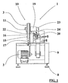
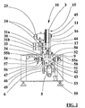
- numeral 1 indicates a punching machine of section bar for roller shutters, according to the preferred embodiment, that essentially comprises a supporting frame 9, moving means 10, punching means 20, feeding means 30, indexer means 40, driving means 50, stop means 15 and fast forward moving means 60.
- This machine 1 is supported by the frame 9 having adjustable feet 8 and to which is connected an adjustable table 7 fit for supporting the section bars to move through the machine along its operating axis and having an adjustable guide 7a, which keeps theses section bars aligned.
- the moving means 10 comprise an electric motor 2 connected by means of belts 4 to a flywheel 3 keyed to a main shaft 11 which is rotationally supported by the frame 9 by means of a bearing central body 19 positioned in between.
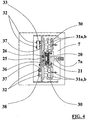
- the punching means 20 comprise a plurality of punches 21, in number of five in the embodiment in figure 4, which are aligned along the motion direction of the section bars and are supported by means of a vertically moving carriage 22 on which a eccentric 23 acts keyed on the main shaft 11 of the moving means 10.
- Said carriage 22, at its upper part, is provided with a tilted surface 24 for contacting the eccentric 23 and is elastically supported by a pair of studs 25 on which are inserted elastic return means 26, in other words, each stud 25 is a guide for a spring 26.
- the feeding means 30 comprise two double pairs of rubber wheels 31 respectively positioned downstream and upstream of the punching means 20.
- the upper pair of rubber wheels 31a is keyed on respective shafts 32 connected to the driving means 50 by a chain 33 which engaged related pinions 34, while the lower double pair of rubber wheels 31b is freely supported by respective shafts 35.
- Two first shafts 32 are connected to the driving means 50 by means of the chain 33 while one of the remaining two shafts 32 is connected to one of these first shafts 32 by a timing belt 36 fit to engage related pulleys 37 keyed to the two connected shafts 32.
- the remaining two shafts 32 are mutually connected by a timing belt 38.
- the indexer means 40 include an indexer 41 on whose input shaft 42 is keyed a pulley 43 connected to a correspondent pulley 45 keyed on the main shaft 11 by a timing belt 44.
- a pulley 47 On the output shaft 46 of the indexer 41 is keyed a pulley 47 connected by means of a timing belt 48 to a correspondent pulley 49 keyed on the input shaft 6 of a variator 5 sequentially connected to the indexer 41 and whose output shaft is connected to the driving means 50 by a timing belt 53 which engages a pulley 59 keyed on the output shaft of the variator 5.
- the driving means 50 comprise a shaft 51 that is rotationally supported by the frame 9 under the adjustable table 7 by interposing a pair of bearings 58.
- the shaft 51 supports a pair of unidirectional rotating "free" wheels, first 55a and second 55b and on which are also keyed a first pulley 52 for connecting the indexer means 40, by means of the timing belt 53, a second pulley 54 for connecting the fast forward moving means 60, by means of a timing belt 56, one of the pinions 34 on which is engaged the chain 33 for connecting the feeding means 30 of the section bars.
- the fast forward moving means 60 comprise a speed motovariator 61 whose output shaft is connected to the driving means 50 by means of a timing belt 56 and by pulleys respectively indicated by the numerals 57 and 62.
- the stop means 15 comprise a flat belt 16 whose middle portion is fit to slide on the flywheel 3 and whose ends are fixed to the stem of a cylinder 17, vertically mobile between two extreme conditions, one is the free condition and another is the stop condition, in which, respectively, the flat belt 16 slides almost without friction on the flywheel 3 and the belt 16 stops by friction the flywheel 3, stopping it.
- the operation of said device provides firstly the setting of the variator 5 and of the speed motovariator 61 to regulate respectively the pitch length between the various series of slots, in the preferred embodiment the number of the slots is five, because five is the number of the punches 21, and then the output speed of the section bars already punched by the machine 1.
- the operation of the electric motor 2 allows the rotation of the main shaft 11, and therefore the rotation of the eccentric 23 that cyclically lowers the carriage 22 supporting the punches 21 toward the adjustable table 7.
- the punches movement and therefore the consequent realization of a series of slots in the section bar is in phase relationship with the stop and the activation of section bar motion and therefore with the stop or the rotation of the rubber wheels 31a of the feeding means 30.
- the rotation of the main shaft 11 causes, in sequence, the rotation of the eccentric 23, the disengaging of the punches 21 from the section bar slots, by means of the spring 26, the restart of the rotation of the output shaft of the indexer 41 and the consequent rotation of both the shaft 51 of the driving means 50, by means of the engaging of the first free wheel 55a, and the rubber wheels 31a, so effecting the forward moving of the section bar of a determined pitch length between a series of slots and the following one.
- the moving means 10 are stopped during a predetermined time interval by means of the activation of the stop means 15, in correspondence of a not punching condition and therefore of not interference of the punches with the section bar.
- the cylinder 17 provides to pull under tension the flat belt 16 that, because of friction, stops the flywheel 3 allowing it only 60 degrees of free rotation before the complete stop and therefore the speed motovariator 61 which provides to activate the rubber wheels 31 a by means of the rotation of the shaft 51 of the driving means 50 by virtue of the kinematic coupling with the second free wheel 55b and because the shaft 51 can freely rotate by means of the first free wheel 55a.
- the activation of the rubber wheels 31a allows therefore the fast moving of the section bar without being punched by the punching means 20. It is important to highlight that the section bars move forward in the machine 1 during the punching at a speed ranging between 60 and 80 meters per minute: the preferable speed is 70 meters per minute, in correspondence of their punching condition.
- section bars are moved or stopped for allowing their punching for a length proportional to the rotation of the main shaft 11 respectively varying from 230 to 250 degrees and from 110 to 130 degrees, and the preferable rotation is 240 degrees in correspondence of the forward moving of the section bar and 120 degrees in correspondence of the punching
- the stop means 15 stop the rotation of the flywheel 3 in a range from 50 to the 70 degrees of the flywheel 3, and the preferable rotation is 60 degrees, as mention above.
- the machine 1 has essentially the same means of the machine according to the preferred embodiment except the fast forward moving means 60, the two pairs of unidirectional moving free wheels, first 55a and second 55b of the driving means 50, while shifting means 70 are provided between the moving means 10 and the punching means 20.
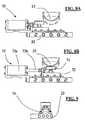
- the shifting means 70 include a stop 71 assembled on a slide 72 horizontally sliding on the carriage 22, this latter without the tilted surface 24, by virtue of guides 74 and actuator means 73, for instance a pneumatic or hydraulic cylinder, whose body 73a is fixed to the carriage 22 and whose stem 73b is fixed to the slide 72.
- actuator means 73 for instance a pneumatic or hydraulic cylinder
- Said actuator 73 moves alternatively the slide 72 between two extreme conditions, the first illustrated in the figures 7A and 8A in which on the stop 71 it acts sliding on the eccentric 23 in correspondence of the punching operation of the section bar, when the punches must be lowered to punch the section bar and a second condition, illustrated in the figures 7B and 8B, in which the stem 73a it is pull back without any interference between the eccentric 23 and the stop 71 in correspondence of the not punching condition of the section bar, when the section bar moves forward.
- the driving means 50 include the shaft 51, rotationally supported by the frame 9 and having a pulley 52 fit for connecting the indexer means 40, by means of the timing belt 53 and the pulley 59.
- a variant of the machine 1 does not provide the use of the stop means 15 because the flywheel 3 that drives the eccentric 23 can rotate continuously also in correspondence of the forward movement of the section bar or in correspondence of the not punching of the same because the shifting means 70 determine the interaction between the eccentric 23 and the punching means 20 and therefore the punching condition of the section bars.
- the main advantage of the present invention is to provide a punching machine to increase the feeding and punching speed of the section bars and also to reduce the wear out of the punches.
- Another advantage is to provide a machine fit to automatically regulate the punching pitch length, keeping it constant, despite of the wear out of the moving means of the section bar.
Landscapes
- Engineering & Computer Science (AREA)
- Mechanical Engineering (AREA)
- Life Sciences & Earth Sciences (AREA)
- Forests & Forestry (AREA)
- Perforating, Stamping-Out Or Severing By Means Other Than Cutting (AREA)
- Metal Rolling (AREA)
Applications Claiming Priority (2)
| Application Number | Priority Date | Filing Date | Title |
|---|---|---|---|
| IT1999BO000247A IT1309246B1 (it) | 1999-05-11 | 1999-05-11 | Apparecchiatura asolatrice di profili per tapparelle |
| ITBO990247 | 1999-05-11 |
Publications (2)
| Publication Number | Publication Date |
|---|---|
| EP1052038A2 true EP1052038A2 (de) | 2000-11-15 |
| EP1052038A3 EP1052038A3 (de) | 2002-07-17 |
Family
ID=11343976
Family Applications (1)
| Application Number | Title | Priority Date | Filing Date |
|---|---|---|---|
| EP00109868A Withdrawn EP1052038A3 (de) | 1999-05-11 | 2000-05-10 | Stanzmaschine für Rolladenprofile |
Country Status (2)
| Country | Link |
|---|---|
| EP (1) | EP1052038A3 (de) |
| IT (1) | IT1309246B1 (de) |
Cited By (4)
| Publication number | Priority date | Publication date | Assignee | Title |
|---|---|---|---|---|
| CN100429016C (zh) * | 2006-11-30 | 2008-10-29 | 张家港联亿电子有限公司 | 一种自动送料装置 |
| CN102974682A (zh) * | 2012-12-20 | 2013-03-20 | 黑龙江昕泰管业有限公司 | 高速打孔机 |
| CN104511549A (zh) * | 2014-12-16 | 2015-04-15 | 衢州市凡工电气科技有限公司 | 一种锥台形工件双面自动进料自动冲压装备 |
| CN115608833A (zh) * | 2022-11-17 | 2023-01-17 | 香河海潮制件有限公司 | 汽车底盘零部件多工位冲压成型装置 |
Family Cites Families (4)
| Publication number | Priority date | Publication date | Assignee | Title |
|---|---|---|---|---|
| BE472282A (de) * | 1941-03-24 | |||
| US3322011A (en) * | 1964-06-15 | 1967-05-30 | Yoder Co | Flying punch |
| US3892154A (en) * | 1973-12-12 | 1975-07-01 | Marcus L Duffy | Structural steel punch |
| US5199339A (en) * | 1990-04-23 | 1993-04-06 | C & M Enterprises, Inc. | H beam hole punch |
-
1999
- 1999-05-11 IT IT1999BO000247A patent/IT1309246B1/it active
-
2000
- 2000-05-10 EP EP00109868A patent/EP1052038A3/de not_active Withdrawn
Cited By (5)
| Publication number | Priority date | Publication date | Assignee | Title |
|---|---|---|---|---|
| CN100429016C (zh) * | 2006-11-30 | 2008-10-29 | 张家港联亿电子有限公司 | 一种自动送料装置 |
| CN102974682A (zh) * | 2012-12-20 | 2013-03-20 | 黑龙江昕泰管业有限公司 | 高速打孔机 |
| CN104511549A (zh) * | 2014-12-16 | 2015-04-15 | 衢州市凡工电气科技有限公司 | 一种锥台形工件双面自动进料自动冲压装备 |
| CN115608833A (zh) * | 2022-11-17 | 2023-01-17 | 香河海潮制件有限公司 | 汽车底盘零部件多工位冲压成型装置 |
| CN115608833B (zh) * | 2022-11-17 | 2023-07-21 | 香河海潮制件有限公司 | 汽车底盘零部件多工位冲压成型装置 |
Also Published As
| Publication number | Publication date |
|---|---|
| ITBO990247A0 (it) | 1999-05-11 |
| EP1052038A3 (de) | 2002-07-17 |
| IT1309246B1 (it) | 2002-01-16 |
| ITBO990247A1 (it) | 2000-11-11 |
Similar Documents
| Publication | Publication Date | Title |
|---|---|---|
| CN209721189U (zh) | 一种线缆输送装置 | |
| EP1052038A2 (de) | Stanzmaschine für Rolladenprofile | |
| CN209618158U (zh) | 一种工装链条输送机 | |
| CN214770160U (zh) | 一种用于轴承座压装的反支撑机构 | |
| CN105856206A (zh) | 智能连杆式机械手 | |
| CN206193760U (zh) | 弹簧式自动售货机兼容互换型皮带输送装置 | |
| CN211517598U (zh) | 一种自控式同步切制机 | |
| CN217295225U (zh) | 一种双驱贴标机构 | |
| CN208413434U (zh) | 模切机的收纸托盘定位装置 | |
| CN205240906U (zh) | 一种改进的摆布机构 | |
| CN212445381U (zh) | 一种自动裁切机 | |
| CN218697956U (zh) | 一种钣金件加工生产用工件夹具 | |
| CN220536642U (zh) | 一种板材切割传送装置 | |
| CN113580236B (zh) | 一种橡胶板用小型切割设备及其切割方法 | |
| CN220743437U (zh) | 一种上下驱动封箱机 | |
| CN219296322U (zh) | 托辊双向自动进给机 | |
| CN201376767Y (zh) | 输送装置 | |
| CN217192182U (zh) | 一种移栽翻转一体机 | |
| CN220075753U (zh) | 一种编织袋切袋机的固定机构 | |
| CN215207614U (zh) | 一种定长可调压力变间隙双驱动送料装置 | |
| CN220011614U (zh) | 模切机的收纸部下拨纸机构 | |
| CN224073213U (zh) | 一种汽车气弹簧支架的生产装置 | |
| CN223950433U (zh) | 一种不干胶标签生产用压平装置 | |
| CN220011076U (zh) | 一种全自动裱纸机的供纸装置 | |
| CN219928882U (zh) | 一种pcb板料的转移机构 |
Legal Events
| Date | Code | Title | Description |
|---|---|---|---|
| PUAI | Public reference made under article 153(3) epc to a published international application that has entered the european phase |
Free format text: ORIGINAL CODE: 0009012 |
|
| AK | Designated contracting states |
Kind code of ref document: A2 Designated state(s): AT BE CH CY DE DK ES FI FR GB GR IE IT LI LU MC NL PT SE |
|
| AX | Request for extension of the european patent |
Free format text: AL;LT;LV;MK;RO;SI |
|
| PUAL | Search report despatched |
Free format text: ORIGINAL CODE: 0009013 |
|
| AK | Designated contracting states |
Kind code of ref document: A3 Designated state(s): AT BE CH CY DE DK ES FI FR GB GR IE IT LI LU MC NL PT SE |
|
| AX | Request for extension of the european patent |
Free format text: AL;LT;LV;MK;RO;SI |
|
| STAA | Information on the status of an ep patent application or granted ep patent |
Free format text: STATUS: THE APPLICATION HAS BEEN WITHDRAWN |
|
| 17P | Request for examination filed |
Effective date: 20030117 |
|
| AKX | Designation fees paid |
Designated state(s): AT BE CH CY DE DK ES FI FR GB GR IE IT LI LU MC NL PT SE |
|
| 18W | Application withdrawn |
Effective date: 20030116 |
|
| D17P | Request for examination filed (deleted) | ||
| DBV | Designated contracting states (deleted) | ||
| REG | Reference to a national code |
Ref country code: DE Ref legal event code: 8566 |