EP1052039A1 - Couvercle de boíte et son procédé de fabrication - Google Patents
Couvercle de boíte et son procédé de fabrication Download PDFInfo
- Publication number
- EP1052039A1 EP1052039A1 EP00304008A EP00304008A EP1052039A1 EP 1052039 A1 EP1052039 A1 EP 1052039A1 EP 00304008 A EP00304008 A EP 00304008A EP 00304008 A EP00304008 A EP 00304008A EP 1052039 A1 EP1052039 A1 EP 1052039A1
- Authority
- EP
- European Patent Office
- Prior art keywords
- panel
- tab
- score
- rolling direction
- lid
- Prior art date
- Legal status (The legal status is an assumption and is not a legal conclusion. Google has not performed a legal analysis and makes no representation as to the accuracy of the status listed.)
- Withdrawn
Links
Images



Classifications
-
- B—PERFORMING OPERATIONS; TRANSPORTING
- B21—MECHANICAL METAL-WORKING WITHOUT ESSENTIALLY REMOVING MATERIAL; PUNCHING METAL
- B21D—WORKING OR PROCESSING OF SHEET METAL OR METAL TUBES, RODS OR PROFILES WITHOUT ESSENTIALLY REMOVING MATERIAL; PUNCHING METAL
- B21D51/00—Making hollow objects
- B21D51/16—Making hollow objects characterised by the use of the objects
- B21D51/38—Making inlet or outlet arrangements of cans, tins, baths, bottles, or other vessels; Making can ends; Making closures
- B21D51/383—Making inlet or outlet arrangements of cans, tins, baths, bottles, or other vessels; Making can ends; Making closures scoring lines, tear strips or pulling tabs
-
- B—PERFORMING OPERATIONS; TRANSPORTING
- B65—CONVEYING; PACKING; STORING; HANDLING THIN OR FILAMENTARY MATERIAL
- B65D—CONTAINERS FOR STORAGE OR TRANSPORT OF ARTICLES OR MATERIALS, e.g. BAGS, BARRELS, BOTTLES, BOXES, CANS, CARTONS, CRATES, DRUMS, JARS, TANKS, HOPPERS, FORWARDING CONTAINERS; ACCESSORIES, CLOSURES, OR FITTINGS THEREFOR; PACKAGING ELEMENTS; PACKAGES
- B65D17/00—Rigid or semi-rigid containers specially constructed to be opened by cutting or piercing, or by tearing of frangible members or portions
- B65D17/28—Rigid or semi-rigid containers specially constructed to be opened by cutting or piercing, or by tearing of frangible members or portions at lines or points of weakness
- B65D17/401—Rigid or semi-rigid containers specially constructed to be opened by cutting or piercing, or by tearing of frangible members or portions at lines or points of weakness characterised by having the line of weakness provided in an end wall
- B65D17/4011—Rigid or semi-rigid containers specially constructed to be opened by cutting or piercing, or by tearing of frangible members or portions at lines or points of weakness characterised by having the line of weakness provided in an end wall for opening completely by means of a tearing tab
Definitions
- the present invention relates to a can lid and a method of manufacturing such a can lid.
- can lids for use on food cans and beverage cans are of the easy-open type having a score for an opening and a tab, and are made of an aluminum alloy.
- various can lids with improved opening score and tab shapes for easier can openability are proposed.
- can lids with identical score and tab shapes can be opened by the user under widely different opening forces. Some can lids require much greater opening forces than other can lids. When such can lids that can be opened under widely different opening forces are used on canned products, they do not meet consumer's needs for easily openable canned products.
- the inventors have found that the positional relationship between the rolling direction of the panel of a can lid and a score and a tab greatly affect an opening force required to open the panel.
- a sheet from which the panel of a can lid is manufactured is supplied as a sheet roll or a sheet length cut from such a sheet roll to a press which blanks a disk-shaped panel out of the sheet.
- the rolling direction of the sheet as it is supplied to the press is kept in alignment with the direction in which the sheet is supplied. After the panel is blanked out of the sheet, since the direction of the blanked panel is not controlled, the rolling direction of the panel is at random.
- a rivet is applied to the panel, a score is notched in the panel, and a tab is fixed to the panel, at a later time, since the rolling direction of the panel is not fixed, can lids thus manufactured need various opening forces to open the panels.
- a can lid comprising a panel machined from a sheet of an aluminum alloy which has been rolled in a predetermined rolling direction, the panel having a score notched in a surface of the panel in a pattern to open the panel, and a tab fixed to the panel by a rivet and having a tip disposed near the score, the table being liftable to tear off the panel along the score to open the panel along the pattern, the score including an initial tear-off line along which the panel can initially be torn off by the tip of the tab, the score being notched such that the rolling direction extends at an angle ranging from 45° to 90° to the initial tear-off line, the tab being oriented in a tab direction lying at an angle of about 90° to the initial tear-off line.
- a can lid or can including a lid portion comprising: a panel machined from a sheet of an aluminum alloy which has been rolled in a predetermined rolling direction, wherein the surface of said panel is scored in a predetermined pattern such that the panel can be torn open; a tab fixed to said panel by means of a rivet and having a tip disposed near said score, said tab being liftable so as to tear the panel along said score thereby causing an opening therein; wherein said score includes an initial tear-off line along which the panel can initially be torn by means of a face exerted by the tip of the tab, said pattern being scored such that said rolling direction extends at an angle ranging from 45° to 90° to said initial tear-off line, and wherein said tab is oriented at an angle of substantially 90° to said initial tear-off line.
- the score is notched such that the rolling direction extends at an angle ranging from 45° to 90° to the initial tear-off line.
- the score thus notched reduces variations in the opening force and reduces the opening force itself, and allows the panel to be opened reliably therealong. If the initial tear-off line is arcuate in shape, then the score is notched such that the direction tangential to the initial tear-off line extends at an angle ranging from 45° to 90° to the rolling direction.
- the opening force required to open the panel along the score is minimum when the initial tear-off line lies substantially perpendicularly to the rolling direction. Therefore, the rolling direction preferably extends at an angle of about 90° to the initial tear-off line.
- the panel has an auxiliary score notched in the surface thereof and positioned across the rivet from the initial tear-off line substantially parallel to the score and separate therefrom.
- the auxiliary score is added to assist the panel in being torn off along the score, and is relatively short.
- the auxiliary score is effective to reduce the opening force required to open the panel along the initial tear-off line.
- the panel has a mark indicative of the rolling direction, the tab being positioned on the mark to conceal the mark from view. Since the mark clearly indicates the rolling direction of the panel, it is easy to keep the angle between the rolling direction and the initial tear-off line within the predetermined range. Inasmuch as the mark is concealed from view by the tab, the can lid has an appearance which is similar to ordinary can lids.
- the direction of the panel can be determined by a line interconnecting the center of the panel and the mark. Therefore, when the line interconnecting the center of the panel and the mark extends at a certain angle to the rolling direction, the mark can be used to represent the relationship between the panel and the rolling direction. Though the relationship between the mark and the rolling direction may be of any arbitrary angle, the line interconnecting the center of the panel and the mark and the rolling direction should preferably extend parallel to each other, or perpendicularly to each other in order to clearly indicate the relationship between the mark and the rolling direction.
- the mark may be printed or formed as a surface irregularity by a press.
- a method of manufacturing a can lid having a panel machined from a sheet of an aluminum alloy which has been rolled in a predetermined rolling direction, the panel having a score notched in a surface of the panel in a pattern to open the panel, and a tab fixed to the panel by a rivet and having a tip disposed near the score, the tab being liftable to tear off the panel along the score to open the panel along the pattern, said score including an initial tear-off line along which the panel can initially be torn off by said tip of the tab, the method comprising the steps of blanking a panel out of a sheet having an indicia of the rolling direction on a surface thereof, orienting the panel such that the rolling direction extends at an angle range from 0° to 45° to a tab direction in which the tab is oriented, applying a rivet to the panel which has been oriented, notching a score in a surface of the panel in a pattern to open the panel along which the panel can initially be torn off
- the sheet from which the panel is formed has is rolling direction clearly indicated by the indicia. Therefore, the panel blanked out of the sheet also has its rolling direction clearly indicated by the indicia.
- the panel Prior to applying the rivet, the panel is oriented such that the rolling direction extends at an angle ranging from 0° to 45° to the tab direction. Sicne the panel has the indicia representative of the rolling direction, the rolling direction can easily be oriented at a desired angle to the tab direction.
- the rivet is applied to the panel, the score is notched in the panel, and the tab is fixed to the panel by the rivet such that the tab direction lies substantially perpendicularly to the initial tear-off line.
- the angle between the rolling direction and the initial tear-off line may be in range from 45° to 90°, the can lid can easily be manufactured which suffer reduced variations in the opening force required to open the panel and which allows the panel to be opened with a relatively small opening force.
- the step of orienting the panel comprises the step of orienting the panel such that the rolling direction and the tab direction are aligned with each other for minimizing the opening force required to open the panel.
- the indicia may comprise a mark applied to the sheet before the panel is blanked out of the sheet, the mark being indicative of the rolling direction.
- the mark indicative of the rolling direction is applied to the sheet before the panel is blanked out of the sheet. Therefore, the panel blanked out of the sheet carries the mark indicative of the rolling direction.
- the indicia may alternatively comprise a striped pattern produced on the sheet when the sheet is rolled, the mark being indicative of the rolling direction. Because the direction of the striped pattern is aligned with the rolling direction at all times, the panel can be oriented on the basis of the striped pattern.
- a can lid 1a is a fully-open-type can lid which comprises a disk-shaped panel 2, a score 3 notched endlessly iii a surface of the panel 2 along an outer circumferential edge of the panel 2, for forming an opening in the panel 2, and a tab 5 fixed to the panel 2 by a rivet 4.
- the surface of the panel 2 which is covered with the tab 5 is printed with a circular mark 6 indicative of the direction in which the panel 2 has been rolled.
- the hatching on the panel 2 and the blank arrow represent the direction R in which the panel 2 has been rolled.
- the mark 6 is printed such that a line interconnecting the center of the panel 2 and the mark 6, i.e., the direction T in which the tab 5 is oriented, lies parallel to the rolling direction R. Actually, the mark 6 is concealed from view by the tab 5.
- the panel 2 is made of an aluminum alloy, and manufactured as follows. First, an aluminum alloy sheet that has been rolled in the rolling direction R as shown in FIG. 1(a) is printed with the mark 6 indicative of the rolling direction R, and a circular area of the sheet which carries the mark 6 is blanked out of the sheet by a press, to form the panel 2.
- the score 3 along which the panel 2 can be torn off by the tab 5 has an initial tear-off line 7 which is straight as viewed in plan.
- the score 3 including the initial tear-off line 7 is formed such that the rolling direction R of the panel 2 is substantially perpendicular to the initial tear-off line 7.
- the panel 2 has an auxiliary score 8 defined in the surface thereof near the rivet 4 and positioned across the rivet 4 from the initial tear-off line 7 substantially parallel to the score 3 and separate therefrom.
- the auxiliary score 8 serves to assist the panel 2 in being torn off along the initial tear-off line 7.
- the tab 5 comprises a fixed region 9 fixed to the panel 2 by the rivet 4, a tip 10 projecting from the fixed region 9 into contact with the initial tear-off line 7, and a ring-shaped finger loop 11 extending from the fixed region 9 remotely from the tip 10 toward the center of the panel 2.
- the tab 5 is secured to the panel 2 such that the tab 5 is oriented substantially perpendicularly to the Initial tear-off line 7.
- the user For tearing off the panel 2 along the score 3 with the tab 5, the user inserts a fingertip into the finger loop 11 and pulls the tab 5 upwardly. Since the tab 5 is fixed to the panel 2 by the rivet 4, the tab 5 is pulled obliquely upwardly, forcing the tip 10 downwardly. The panel 2 is first torn off along the auxiliary score 8, and then torn off along the initial tear-off line 7 by the tip 10 which is being depressed.
- the user After the panel 2 is initially torn off along the initial tear-off line 7, the user further pulls the finger loop 11 upwardly to tear off the panel 2 progressively along the score 3 until the circular portion of the panel 2 within the score 3 is entirely torn off, whereupon a circular opening is formed in the panel 2 for the user to gain access to the contents of the can.
- the can lid 1a shown in FIG. 1(a), a can lid 1b shown in FIG. 1(b), and a can lid 100 according to a comparative example shown in FIG. 1(c) were measured for opening forces required to open them.
- the opening forces were measured using an opening force measuring device 12 shown in FIGS. 2(a) and 2(b).
- Ten samples of the can lid 1a and ten samples of the can lid 1b were randomly taken from production lots and measured.
- the can lid 100 shown in FIG. 1(c) according to the comparative example has a score 3 including an initial tear-off line 7 which extends such that the rolling direction R of the panel extends substantially parallel to the initial tear-off line 7.
- Ten samples of the can lid 100 were selected from conventional can lids and measured.
- the opening force measuring device 12 has a load cell 14 mounted on a swingable arm 13 and a hook 16 connected to the load cell 14 by a chain 15.
- the opening force measuring device 12 also has a can lid base 17 for placing a can lid thereon.
- the opening force measuring device 12 measures a can lid opening force as follows: As shown in FIG. 2(a), the can lid 1a, 1b, 100 is placed on the can lid base 17, and the hook 16 is positioned in engagement with the finger loop 11 of the tab 5. Then, as shown in FIG. 2(b), the arm 13 is turned to cause the hook 16 to pull the tab 5, and the load cell 14 measure an opening force that is required to open the panel of the can lid 1a, 1b, 100.
- Opening forces required to open the panels of the can lids 1a, 1b, 100 under the above conditions are set forth in Table shown below.
- the numerical values of the opening forces are expressed in N (Newton), and the numbers 1 - 10 represent sample numbers.
- Can lid 1a Can lid 1b
- Can lid 100 1 18.1 18.8 22.1 2 17.4 19.5 21.7 3 17.9 18.6 22.6 4 17.9 19.1 20.6 5 17.8 17.9 22.6 6 18.3 18.0 20.9 7 17.7 18.0 20.1 8 18.0 18.2 19.8 9 17.9 18.4 19.1 10 18.0 18.3 19.7 Average 17.9 18. 5 20.9
- the average opening force required for the can lid 1a was 17.9 N
- the average opening force required for the can lid 1b was 18.5 N
- the average opening force required for the conventional can lid 100 was 20.9 N. It can be seen that the panel 2 of the can lid 1a can be opened with an opening force smaller than the panel of the conventional can lid 100.
- the panel of the can lid 1b can also be opened with an opening force smaller than the panel of the conventional can lid 100 though the opening force required for the can lid 1b is slightly greater than the opening force required for the can lid 1a.
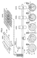
- a method of manufacturing the can lid 1a will be described below with reference to FIGS. 4 and 5.
- a sheet 20 which has been rolled in a rolling direction R is delivered in the rolling direction and printed with circular marks 6 in STEP1 according to a mark printing process. As shown in FIG. 1(a), the marks 6 are printed at a position which is clearly indicative of the rolling direction R when panels 2 are blanked out of the sheet 20 in a next blanking process, and which will be concealed by tabs 5.
- circular panels 2 including the respective marks 6 are blanked out of the sheet 20 by a press (not shown) in STEP2.
- the panels 2 are separated from the sheet 20 and stacked by a stacker (not shown).
- the rolling directions R of the respective panels 2 are not controlled, but are oriented at random.
- the rolling directions R of the respective panels 2 are aligned with a tab direction T in which tabs 5 will be oriented in STEP3.
- the image of a delivered panel 2 is recognized by a camera 18 to detect the position of the mark 6 printed on the panel 2, and the rolling direction R is recognized from the detected position of the mark 6.
- an angle through which the rolling direction R is to be angularly displaced into alignment with the tab direction T is calculated.
- the panel 2 is turned through the calculated angle by a turning device 19 until the rolling direction R is aligned with the tab direction T.
- the panel 2 is now oriented such that the rolling direction R is aligned with the tab direction T.
- a rivet 4 is applied to the panel 2 which has been oriented such that the rolling direction R is aligned with the tab direction T in STEP4. Specifically, an area of the panel 2 where a tab 5 will be attached is pressed so as to be partly raised and then shaped into a substantially cylindrical shape by a press. In a next score notching process, a score 3 and an auxiliary score 8 are notched in the panel 2 to which the rivet 4 has been applied in STEP5. In a tab fixing process, a tab 5 is fixed to the panel 2 in which the score 3 and the auxiliary score 8 have been notched in STEP6. In the tab fixing process, specifically, the applied rivet 4 which is of a cylindrical shape is fitted in a through hole defined in the fixed region 9 of the tab 5, and an upper end of the rivet 4 is then pressed to secure the tab 5 to the panel 2 with the rivet 4.
- the rolling direction R lies substantially perpendicularly to the initial tear-off line 7 of the score 3
- the tab direction T also lies substantially perpendicularly to the initial tear-off line 7 of the score 3. Since the opening force required to open the panel 2 of the can lid 1a thus constructed is relatively small, as can be seen from Table given above, the manufacturing method described above is capable of manufacturing a can lid whose panel 2 can be opened with a relatively small opening force.
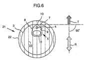
- FIG. 6 shows a can lid 21 according to a second embodiment of the present invention.
- Those parts of the can lid 21 which are identical to those of the can lids according to the first embodiment of the present invention are denoted by identical reference characters, and will not be described in detail below.
- the sheet according to the second embodiment is a fully-open-type can lid.
- the can lid 21 has a circular panel 22 made of an aluminum alloy, and is blanked out of a sheet which has been rolled in the rolling direction R as shown in FIG. 6. No mark is printed on the panel 22, but a striped pattern 23 produced when the can lid 21 has been rolled appears on the surface of the panel 22.
- circular panels 22 are blanked from a sheet which has been rolled in the rolling direction R.
- the panels 22 are separated from the sheet and stacked by a stacker (not shown).
- the rolling directions R of the respective panels 22 are not controlled, but are oriented at random.
- the rolling directions R of the respective panels 22 are aligned with a tab direction T in which tabs 5 will be oriented in STEP3.
- a light beam from a light source 24 is applied to the surface of a panel 22 which has been delivered, and while the panel 22 is tuned 360° by a tuning device 25, a light beam reflected from an outer circumferential surface region of the panel 22 is detected by a sensor 26. Since the light beam reflected by the surface of the panel 22 interferes with the striped pattern 23 thereon, the reflected light beam represents intensity variations due to the striped pattern 23.
- the rolling direction R of the panel 22 is detected on the basis of the intensity variations of the reflected light.
- an angle through which the rolling direction R is to be angularly displaced into alignment with the tab direction T is calculated based on the striped pattern 23.
- the panel 22 is turned through the calculated angle by a turning device 19 until the rolling direction R is aligned with the tab direction T.
- the panel 22 is now oriented such that the rolling direction R is aligned with the tab direction T.
- a rivet 4 is applied to the panel 22 in a riveting process in STEP4, a score 3 and an auxiliary score 8 are notched in the panel 22 in a score notching process in STEP5, and a tab 5 is fixed to the panel 22 in a tab fixing process in STEP6.
- the rolling direction R lies substantially perpendicularly to the initial tear-off line 7 of the score 3
- the tab direction T also lies substantially perpendicularly to the initial tear-off line 7 of the score 3.
- the opening force required to open the panel 22 of the can lid 21 thus constructed is relatively small, and the manufacturing method described above is capable of manufacturing a can lid whose panel 22 can be opened with a relatively small opening force.
- the method of manufacturing a can lid according to the present invention which is slightly modified from a conventional manufacturing method, is capable of manufacturing can lids which can reliably be opened with a relatively small opening force free of large variations, without incurring a substantially increase in the cost.
- the principles of the present invention are also applicable to a partially-open-type can lid, e.g., a stay-on-tab can lid.
- the striped pattern produced when an aluminum alloy is rolled in a direction has been described by way of example as the indicia indicative of the rolling direction.
- the indicia indicative of the rolling direction may alternatively be another pattern on the panel, an instruction remark explanatory of how to use the tab, or the like.
Landscapes
- Engineering & Computer Science (AREA)
- Mechanical Engineering (AREA)
- Containers Opened By Tearing Frangible Portions (AREA)
Applications Claiming Priority (2)
| Application Number | Priority Date | Filing Date | Title |
|---|---|---|---|
| JP13112199 | 1999-05-12 | ||
| JP13112199 | 1999-05-12 |
Publications (1)
| Publication Number | Publication Date |
|---|---|
| EP1052039A1 true EP1052039A1 (fr) | 2000-11-15 |
Family
ID=15050486
Family Applications (1)
| Application Number | Title | Priority Date | Filing Date |
|---|---|---|---|
| EP00304008A Withdrawn EP1052039A1 (fr) | 1999-05-12 | 2000-05-12 | Couvercle de boíte et son procédé de fabrication |
Country Status (1)
| Country | Link |
|---|---|
| EP (1) | EP1052039A1 (fr) |
Cited By (9)
| Publication number | Priority date | Publication date | Assignee | Title |
|---|---|---|---|---|
| EP1055468A3 (fr) * | 1999-05-18 | 2002-08-21 | Showa Seiki Co., Ltd. | Dispositif de fabriquer un couvercle de boíte |
| KR100436996B1 (ko) * | 2001-09-25 | 2004-06-23 | 주식회사 씨솔루션 | 탭 코일의 파일롯트 홀을 이용한 디자인 탭 엔드 제조방법 |
| KR100493859B1 (ko) * | 2002-02-22 | 2005-06-08 | 이도희 | 파일롯트 홀을 이용한 선인쇄 후성형 방식의 디자인 탭엔드 제조방법 |
| KR100747666B1 (ko) * | 2002-06-19 | 2007-08-08 | 이도희 | 파일롯트 홀을 이용한 선인쇄 후성형 방식의 디자인 탭엔드 제조장치 및 그 방법 |
| WO2010037998A1 (fr) * | 2008-09-04 | 2010-04-08 | Elopak Systems Ag | Appareil et procédé d'orientation de capsule |
| EP2160332A4 (fr) * | 2007-06-22 | 2011-08-10 | Stolle Machinery Co Llc | Couvercle de boîte-boisson et procédé de fabrication de celui-ci |
| ITUB20150183A1 (it) * | 2015-05-12 | 2016-11-12 | Mec Project Di Brossa Roberto | Processo e macchinario per orientare e formare una placca per una gabbia di un tappo |
| EP3402618A4 (fr) * | 2016-01-13 | 2019-11-20 | Ball Corporation | Système et procédé d'orientation de la direction de laminage d'une ébauche d'extrémité dans un processus de fabrication de récipients métalliques |
| PL237279B1 (pl) * | 2014-07-16 | 2021-03-22 | Can Pack Spolka Akcyjna | Sposób wykonania nadruku na wieczku puszki |
Citations (3)
| Publication number | Priority date | Publication date | Assignee | Title |
|---|---|---|---|---|
| US3628650A (en) * | 1969-11-14 | 1971-12-21 | American Can Co | Apparatus for orienting can ends |
| CH517025A (de) * | 1970-10-09 | 1971-12-31 | Hoffmann Ag Geb | Behälterteil, insbesondere Deckel für eine Dose |
| WO1998055366A1 (fr) * | 1997-06-03 | 1998-12-10 | Crown Cork & Seal Technologies Corporation | Couvercle de boite a ouverture facile |
-
2000
- 2000-05-12 EP EP00304008A patent/EP1052039A1/fr not_active Withdrawn
Patent Citations (3)
| Publication number | Priority date | Publication date | Assignee | Title |
|---|---|---|---|---|
| US3628650A (en) * | 1969-11-14 | 1971-12-21 | American Can Co | Apparatus for orienting can ends |
| CH517025A (de) * | 1970-10-09 | 1971-12-31 | Hoffmann Ag Geb | Behälterteil, insbesondere Deckel für eine Dose |
| WO1998055366A1 (fr) * | 1997-06-03 | 1998-12-10 | Crown Cork & Seal Technologies Corporation | Couvercle de boite a ouverture facile |
Cited By (12)
| Publication number | Priority date | Publication date | Assignee | Title |
|---|---|---|---|---|
| EP1055468A3 (fr) * | 1999-05-18 | 2002-08-21 | Showa Seiki Co., Ltd. | Dispositif de fabriquer un couvercle de boíte |
| KR100436996B1 (ko) * | 2001-09-25 | 2004-06-23 | 주식회사 씨솔루션 | 탭 코일의 파일롯트 홀을 이용한 디자인 탭 엔드 제조방법 |
| KR100493859B1 (ko) * | 2002-02-22 | 2005-06-08 | 이도희 | 파일롯트 홀을 이용한 선인쇄 후성형 방식의 디자인 탭엔드 제조방법 |
| KR100747666B1 (ko) * | 2002-06-19 | 2007-08-08 | 이도희 | 파일롯트 홀을 이용한 선인쇄 후성형 방식의 디자인 탭엔드 제조장치 및 그 방법 |
| EP2160332A4 (fr) * | 2007-06-22 | 2011-08-10 | Stolle Machinery Co Llc | Couvercle de boîte-boisson et procédé de fabrication de celui-ci |
| US8109405B2 (en) | 2007-06-22 | 2012-02-07 | Stolle Machinery Company, Llc | Can end and rivet base scoreline therefor |
| WO2010037998A1 (fr) * | 2008-09-04 | 2010-04-08 | Elopak Systems Ag | Appareil et procédé d'orientation de capsule |
| PL237279B1 (pl) * | 2014-07-16 | 2021-03-22 | Can Pack Spolka Akcyjna | Sposób wykonania nadruku na wieczku puszki |
| ITUB20150183A1 (it) * | 2015-05-12 | 2016-11-12 | Mec Project Di Brossa Roberto | Processo e macchinario per orientare e formare una placca per una gabbia di un tappo |
| WO2016181305A1 (fr) * | 2015-05-12 | 2016-11-17 | Mec Project Di Brossa Roberto | Procédé et machinerie pour orienter et former une plaque pour un muselet |
| EA034640B1 (ru) * | 2015-05-12 | 2020-03-02 | Мек Проект Ди Бросса Роберто | Способ и оборудование для ориентирования и формования плакетки для проволочного фиксатора пробки |
| EP3402618A4 (fr) * | 2016-01-13 | 2019-11-20 | Ball Corporation | Système et procédé d'orientation de la direction de laminage d'une ébauche d'extrémité dans un processus de fabrication de récipients métalliques |
Similar Documents
| Publication | Publication Date | Title |
|---|---|---|
| US6524048B1 (en) | Apparatus for manufacturing can lid | |
| US4465204A (en) | Pull tab for easy open end | |
| US4530631A (en) | Pull tab for easy open can end-method of manufacture thereof | |
| US5129541A (en) | Easy open ecology end for cans | |
| CA2292649C (fr) | Couvercle de boite a ouverture facile | |
| EP0993408B1 (fr) | Fermeture d'extremite a ouverture amelioree | |
| US20070108209A1 (en) | Easily openable can lid | |
| US5092467A (en) | Shipping and display container | |
| EP1034054B1 (fr) | Languette pour couvercle de contenant et procede de fabrication | |
| US7909196B2 (en) | Can end with tab for improved accessibility | |
| GB2050993A (en) | Easy-open container closures | |
| US5449538A (en) | Label/leaflet assemblies | |
| EP0399623A3 (fr) | Dispositif d'empilage de carton ondulé | |
| CA2068731A1 (fr) | Boite en carton a entailles perforees et decoupe correspondante | |
| WO2002059011A3 (fr) | Carton d'emballage pour articles à collerette | |
| WO2004065236A1 (fr) | Couvercle d'extremite muni d'une languette antirotation | |
| US20080110888A1 (en) | Can end with incising and method for producing same | |
| GB2276147A (en) | Tear strips for opening boxes | |
| US3356250A (en) | Container and tear strip type lid therefor | |
| CN120584078A (zh) | 带有阻隔构件的容器 | |
| CA1264683A (fr) | Bande d'arrachement pour ouverture de boite | |
| JP2001031087A (ja) | 缶蓋及びその製造方法 | |
| US3744708A (en) | Structure for folding carton | |
| CN115165916A (zh) | 安全项检测方法和系统 | |
| JP2582386Y2 (ja) | イージーオープン缶蓋 |
Legal Events
| Date | Code | Title | Description |
|---|---|---|---|
| PUAI | Public reference made under article 153(3) epc to a published international application that has entered the european phase |
Free format text: ORIGINAL CODE: 0009012 |
|
| AK | Designated contracting states |
Kind code of ref document: A1 Designated state(s): DE FR GB |
|
| AX | Request for extension of the european patent |
Free format text: AL;LT;LV;MK;RO;SI |
|
| 17P | Request for examination filed |
Effective date: 20001218 |
|
| AKX | Designation fees paid |
Free format text: DE FR GB |
|
| 17Q | First examination report despatched |
Effective date: 20031112 |
|
| STAA | Information on the status of an ep patent application or granted ep patent |
Free format text: STATUS: THE APPLICATION IS DEEMED TO BE WITHDRAWN |
|
| 18D | Application deemed to be withdrawn |
Effective date: 20040323 |