EP1052048B1 - Machine outil pour l'usinage des vilebrequins - Google Patents
Machine outil pour l'usinage des vilebrequins Download PDFInfo
- Publication number
- EP1052048B1 EP1052048B1 EP00108744A EP00108744A EP1052048B1 EP 1052048 B1 EP1052048 B1 EP 1052048B1 EP 00108744 A EP00108744 A EP 00108744A EP 00108744 A EP00108744 A EP 00108744A EP 1052048 B1 EP1052048 B1 EP 1052048B1
- Authority
- EP
- European Patent Office
- Prior art keywords
- tool
- machine tool
- magazine
- spindle
- headstock
- Prior art date
- Legal status (The legal status is an assumption and is not a legal conclusion. Google has not performed a legal analysis and makes no representation as to the accuracy of the status listed.)
- Expired - Lifetime
Links
Images




Classifications
-
- B—PERFORMING OPERATIONS; TRANSPORTING
- B23—MACHINE TOOLS; METAL-WORKING NOT OTHERWISE PROVIDED FOR
- B23B—TURNING; BORING
- B23B41/00—Boring or drilling machines or devices specially adapted for particular work; Accessories specially adapted therefor
- B23B41/12—Boring or drilling machines or devices specially adapted for particular work; Accessories specially adapted therefor for forming working surfaces of cylinders, of bearings, e.g. in heads of driving rods, or of other engine parts
-
- B—PERFORMING OPERATIONS; TRANSPORTING
- B23—MACHINE TOOLS; METAL-WORKING NOT OTHERWISE PROVIDED FOR
- B23Q—DETAILS, COMPONENTS, OR ACCESSORIES FOR MACHINE TOOLS, e.g. ARRANGEMENTS FOR COPYING OR CONTROLLING; MACHINE TOOLS IN GENERAL CHARACTERISED BY THE CONSTRUCTION OF PARTICULAR DETAILS OR COMPONENTS; COMBINATIONS OR ASSOCIATIONS OF METAL-WORKING MACHINES, NOT DIRECTED TO A PARTICULAR RESULT
- B23Q1/00—Members which are comprised in the general build-up of a form of machine, particularly relatively large fixed members
- B23Q1/25—Movable or adjustable work or tool supports
- B23Q1/44—Movable or adjustable work or tool supports using particular mechanisms
- B23Q1/48—Movable or adjustable work or tool supports using particular mechanisms with sliding pairs and rotating pairs
- B23Q1/4852—Movable or adjustable work or tool supports using particular mechanisms with sliding pairs and rotating pairs a single sliding pair followed perpendicularly by a single rotating pair
- B23Q1/4857—Movable or adjustable work or tool supports using particular mechanisms with sliding pairs and rotating pairs a single sliding pair followed perpendicularly by a single rotating pair followed perpendicularly by a single rotating pair
-
- B—PERFORMING OPERATIONS; TRANSPORTING
- B23—MACHINE TOOLS; METAL-WORKING NOT OTHERWISE PROVIDED FOR
- B23Q—DETAILS, COMPONENTS, OR ACCESSORIES FOR MACHINE TOOLS, e.g. ARRANGEMENTS FOR COPYING OR CONTROLLING; MACHINE TOOLS IN GENERAL CHARACTERISED BY THE CONSTRUCTION OF PARTICULAR DETAILS OR COMPONENTS; COMBINATIONS OR ASSOCIATIONS OF METAL-WORKING MACHINES, NOT DIRECTED TO A PARTICULAR RESULT
- B23Q1/00—Members which are comprised in the general build-up of a form of machine, particularly relatively large fixed members
- B23Q1/25—Movable or adjustable work or tool supports
- B23Q1/44—Movable or adjustable work or tool supports using particular mechanisms
- B23Q1/50—Movable or adjustable work or tool supports using particular mechanisms with rotating pairs only, the rotating pairs being the first two elements of the mechanism
- B23Q1/54—Movable or adjustable work or tool supports using particular mechanisms with rotating pairs only, the rotating pairs being the first two elements of the mechanism two rotating pairs only
- B23Q1/5406—Movable or adjustable work or tool supports using particular mechanisms with rotating pairs only, the rotating pairs being the first two elements of the mechanism two rotating pairs only a single rotating pair followed perpendicularly by a single rotating pair
-
- B—PERFORMING OPERATIONS; TRANSPORTING
- B23—MACHINE TOOLS; METAL-WORKING NOT OTHERWISE PROVIDED FOR
- B23Q—DETAILS, COMPONENTS, OR ACCESSORIES FOR MACHINE TOOLS, e.g. ARRANGEMENTS FOR COPYING OR CONTROLLING; MACHINE TOOLS IN GENERAL CHARACTERISED BY THE CONSTRUCTION OF PARTICULAR DETAILS OR COMPONENTS; COMBINATIONS OR ASSOCIATIONS OF METAL-WORKING MACHINES, NOT DIRECTED TO A PARTICULAR RESULT
- B23Q11/00—Accessories fitted to machine tools for keeping tools or parts of the machine in good working condition or for cooling work; Safety devices specially combined with or arranged in, or specially adapted for use in connection with, machine tools
- B23Q11/08—Protective coverings for parts of machine tools; Splash guards
- B23Q11/0891—Protective coverings for parts of machine tools; Splash guards arranged between the working area and the operator
-
- B—PERFORMING OPERATIONS; TRANSPORTING
- B23—MACHINE TOOLS; METAL-WORKING NOT OTHERWISE PROVIDED FOR
- B23Q—DETAILS, COMPONENTS, OR ACCESSORIES FOR MACHINE TOOLS, e.g. ARRANGEMENTS FOR COPYING OR CONTROLLING; MACHINE TOOLS IN GENERAL CHARACTERISED BY THE CONSTRUCTION OF PARTICULAR DETAILS OR COMPONENTS; COMBINATIONS OR ASSOCIATIONS OF METAL-WORKING MACHINES, NOT DIRECTED TO A PARTICULAR RESULT
- B23Q3/00—Devices holding, supporting, or positioning work or tools, of a kind normally removable from the machine
- B23Q3/155—Arrangements for automatic insertion or removal of tools, e.g. combined with manual handling
- B23Q3/157—Arrangements for automatic insertion or removal of tools, e.g. combined with manual handling of rotary tools
- B23Q3/15706—Arrangements for automatic insertion or removal of tools, e.g. combined with manual handling of rotary tools a single tool being inserted in a spindle directly from a storage device, i.e. without using transfer devices
-
- B—PERFORMING OPERATIONS; TRANSPORTING
- B23—MACHINE TOOLS; METAL-WORKING NOT OTHERWISE PROVIDED FOR
- B23B—TURNING; BORING
- B23B2215/00—Details of workpieces
- B23B2215/20—Crankshafts
-
- Y—GENERAL TAGGING OF NEW TECHNOLOGICAL DEVELOPMENTS; GENERAL TAGGING OF CROSS-SECTIONAL TECHNOLOGIES SPANNING OVER SEVERAL SECTIONS OF THE IPC; TECHNICAL SUBJECTS COVERED BY FORMER USPC CROSS-REFERENCE ART COLLECTIONS [XRACs] AND DIGESTS
- Y10—TECHNICAL SUBJECTS COVERED BY FORMER USPC
- Y10T—TECHNICAL SUBJECTS COVERED BY FORMER US CLASSIFICATION
- Y10T408/00—Cutting by use of rotating axially moving tool
- Y10T408/36—Machine including plural tools
- Y10T408/38—Plural, simultaneously operational tools
- Y10T408/3839—Plural, simultaneously operational tools with presser-foot
-
- Y—GENERAL TAGGING OF NEW TECHNOLOGICAL DEVELOPMENTS; GENERAL TAGGING OF CROSS-SECTIONAL TECHNOLOGIES SPANNING OVER SEVERAL SECTIONS OF THE IPC; TECHNICAL SUBJECTS COVERED BY FORMER USPC CROSS-REFERENCE ART COLLECTIONS [XRACs] AND DIGESTS
- Y10—TECHNICAL SUBJECTS COVERED BY FORMER USPC
- Y10T—TECHNICAL SUBJECTS COVERED BY FORMER US CLASSIFICATION
- Y10T409/00—Gear cutting, milling, or planing
- Y10T409/30—Milling
- Y10T409/304536—Milling including means to infeed work to cutter
- Y10T409/305544—Milling including means to infeed work to cutter with work holder
- Y10T409/305656—Milling including means to infeed work to cutter with work holder including means to support work for rotation during operation
-
- Y—GENERAL TAGGING OF NEW TECHNOLOGICAL DEVELOPMENTS; GENERAL TAGGING OF CROSS-SECTIONAL TECHNOLOGIES SPANNING OVER SEVERAL SECTIONS OF THE IPC; TECHNICAL SUBJECTS COVERED BY FORMER USPC CROSS-REFERENCE ART COLLECTIONS [XRACs] AND DIGESTS
- Y10—TECHNICAL SUBJECTS COVERED BY FORMER USPC
- Y10T—TECHNICAL SUBJECTS COVERED BY FORMER US CLASSIFICATION
- Y10T483/00—Tool changing
- Y10T483/11—Tool changing with safety means
- Y10T483/115—Guard
-
- Y—GENERAL TAGGING OF NEW TECHNOLOGICAL DEVELOPMENTS; GENERAL TAGGING OF CROSS-SECTIONAL TECHNOLOGIES SPANNING OVER SEVERAL SECTIONS OF THE IPC; TECHNICAL SUBJECTS COVERED BY FORMER USPC CROSS-REFERENCE ART COLLECTIONS [XRACs] AND DIGESTS
- Y10—TECHNICAL SUBJECTS COVERED BY FORMER USPC
- Y10T—TECHNICAL SUBJECTS COVERED BY FORMER US CLASSIFICATION
- Y10T483/00—Tool changing
- Y10T483/17—Tool changing including machine tool or component
- Y10T483/1733—Rotary spindle machine tool [e.g., milling machine, boring, machine, grinding machine, etc.]
- Y10T483/1736—Tool having specific mounting or work treating feature
-
- Y—GENERAL TAGGING OF NEW TECHNOLOGICAL DEVELOPMENTS; GENERAL TAGGING OF CROSS-SECTIONAL TECHNOLOGIES SPANNING OVER SEVERAL SECTIONS OF THE IPC; TECHNICAL SUBJECTS COVERED BY FORMER USPC CROSS-REFERENCE ART COLLECTIONS [XRACs] AND DIGESTS
- Y10—TECHNICAL SUBJECTS COVERED BY FORMER USPC
- Y10T—TECHNICAL SUBJECTS COVERED BY FORMER US CLASSIFICATION
- Y10T483/00—Tool changing
- Y10T483/17—Tool changing including machine tool or component
- Y10T483/1733—Rotary spindle machine tool [e.g., milling machine, boring, machine, grinding machine, etc.]
- Y10T483/179—Direct tool exchange between spindle and matrix
- Y10T483/1793—Spindle comprises tool changer
-
- Y—GENERAL TAGGING OF NEW TECHNOLOGICAL DEVELOPMENTS; GENERAL TAGGING OF CROSS-SECTIONAL TECHNOLOGIES SPANNING OVER SEVERAL SECTIONS OF THE IPC; TECHNICAL SUBJECTS COVERED BY FORMER USPC CROSS-REFERENCE ART COLLECTIONS [XRACs] AND DIGESTS
- Y10—TECHNICAL SUBJECTS COVERED BY FORMER USPC
- Y10T—TECHNICAL SUBJECTS COVERED BY FORMER US CLASSIFICATION
- Y10T483/00—Tool changing
- Y10T483/17—Tool changing including machine tool or component
- Y10T483/1733—Rotary spindle machine tool [e.g., milling machine, boring, machine, grinding machine, etc.]
- Y10T483/179—Direct tool exchange between spindle and matrix
- Y10T483/1793—Spindle comprises tool changer
- Y10T483/1795—Matrix indexes selected tool to transfer position
Definitions
- the invention relates to a machine tool for machining Crankshafts and especially for drilling oil holes as Oblique bores in crankshafts.
- Crankshafts have several main bearings along their main axis and pin bearings on the bends.
- oblique holes are made, which extend from a pin bearing extend through the bend into the main bearing. Such holes are relatively long and require their production a very precise oblique alignment of the crankshaft.
- a machine tool for drilling holes in crankshafts, from which the preamble of claim 1 is based is described in US 5,759,140.
- This machine tool has a workpiece carrier with two clamping devices, two crankshafts can be machined synchronously.
- the workpiece holder can be pivoted about a horizontal transverse axis, whereby he can assume such an inclination that the horizontally aligned and horizontally guided tools hit the crankshafts at the desired drilling angle.
- the headstock becomes more vertical Direction shifted.
- the one inserted in the spindles Tools (drills) are assigned to drill bushings.
- the Tools and drill bushes are taken from a factory magazine and can be changed automatically.
- the machine tool has one arranged on a horizontal turntable Workpiece carrier on which crankshafts in horizontal alignment. Two of opposite Spindles acting in directions, each with a drilling tool wear, are aimed at the crankshafts.
- DE 195 10 498 A1 describes a machine tool in which a Stand can be moved in the horizontal direction.
- the stand carries a headstock that can be moved in the vertical direction, a tool is attached to the spindle.
- the workpiece carrier is a turntable that rotates around a vertical axis is.
- the turntable is in the direction of attack, i.e. towards the tool there, movable.
- a tool magazine with a tool changer is intended to replace the tool on the spindle.
- EP 0 483 781 A2 describes a machine tool with a tool magazine and an associated tool changer. This machine tool is for machining crankshafts not specifically determined.
- the invention has for its object an improved Machine tool for machining crankshafts with horizontal to create aligned spindle, which in spatial and kinematically simplified and simple Allows feeding of the crankshafts.
- the workpiece carrier has two superimposed ones Jigs, so that two crankshafts in parallel and can be edited on top of each other at the same time.
- the Jigs are on one around a horizontal axis swiveling holder attached, for changing the workpieces from a vertical position to a horizontal position is pivotable.
- the workpiece carrier to create the oblique holes around a vertical Axis rotated.
- the crankshaft is always horizontal Alignment held.
- the required helix angle is in on a horizontal level.
- the crankshaft will so fixed with horizontal crankshaft plane, while the Inclination is caused by turning the turntable. This is especially the case for Crankshaft machining and changing the crankshaft needed Reduced space requirements.
- the one that rotates around a vertical axis The turntable always keeps the crankshaft in a horizontal position Alignment firmly so that it is possible to use the crankshaft feed and insert horizontally running longitudinal axis.
- the headstock is preferably on a vertical slide on a fixed stand between a working position and a stroke position vertically movable. At the height of the lifting position there is a tool magazine for direct tool transfer to and from the spindle. During the machining process the headstock always remains at the level of the working position.
- the headstock can be adjusted vertically, since the holes to be drilled generally do not open the middle of the camp. The vertical adjustment also serves to be able to move the headstock to a lifting position, in which he works with a tool magazine.
- This Tool magazine is located above the processing level, so that it is also easily possible to find those in the tool magazine Tools during the operation of the machine tool replaced.
- the headstock has one for each spindle assigned drill bushing rod, which has a replaceable Drill bush carries in regardless of the associated spindle Is movable in the longitudinal direction.
- the drill bushes are used for guidance the drill and are placed against the workpiece.
- the drill bush holder are provided with their own drive to to the respective position of the workpiece from the vertical slide to be pulled out. While the tool with the Headstock is moved in the axial direction of the spindle the drill sleeve holder from the vertical slide that the Headstock carries. This keeps the drill bushing during the Drilling feed firmly.
- the longitudinal adjustability of the drill bush is required to adjust the drill bushing to the respective distance adjust the crankshaft that is inclined in the horizontal plane to be able to.
- the tool magazine has a first circulation magazine for tools and a second circulation magazine for drill bushes.
- both circulation magazines are controlled independently of each other driven such that different tools with same drill bushing can be aligned. Usually wear out the tools faster than the drill bushings. It is therefore possible to use the same drill bushing for several tools use.
- the independent control of the two circulation magazines allows tool and drill bush to be connected with each other as required combine.
- crankshaft 10 The machine tool is used for machining crankshafts
- the machine tool has a machine bed 11, of which a stand 12 rises.
- the machine bed 11 is with a horizontal guide 13 provided on which a horizontal slide 14th is controlled controlled.
- the horizontal slide 14 applies a turntable 15 a workpiece holder 16.
- the workpiece holder 16 has two uprights rising from the turntable 15 17, each pivotable about a horizontal axis 18 Holder 19 with two jigs 20,21 for one Wear the crankshaft.
- the jig 20 on one The end is a chuck attached to a flange of the crankshaft attacks while the other clamping device 21 as a tailstock is trained.
- the clamping devices 20, 21 hold the respective ones Crankshaft 10 or 10a in the correct position.
- the jigs but also have a (not shown) Rotary drive to the clamped crankshaft for the drilling positions to rotate separately.
- a vertically movable vertical slide 22 can be moved in a controlled manner along a vertical guide 23.
- the vertical slide 22 carries a headstock 24, which can be moved horizontally on the vertical slide.
- the Headstock 24 contains two spindles 25, 25a, one above the other are arranged in a vertical plane.
- a tool 26, 26a is clamped in each of the spindles 25, 25a.
- These tools are elongated Drill to create the oblique holes in the crankshafts.
- a drill bushing 27, 27a is assigned to each tool 26, 26a.
- the drill bushings can be exchanged on a drill bush holder 28, 28a attached, which is carried by a drill bushing rod 29,29a becomes.
- the drill bushing rods 29 and 29a are from that Vertical slide 22 and they are controlled by each a provided on the vertical slide 22 (not shown) Drive can be moved in the longitudinal direction.
- the drill sleeve rod axially slidably mounted and can by an independent Adjustment device (here hydraulic cylinder) in several axial Positions are positioned relative to the tool.
- the headstock 24 becomes like this according to a) moved far to the workpiece until a contact under a certain Contact pressure to the workpiece arises.
- the drill bush always remains in contact during the subsequent drilling process with the workpiece, what by a controlled / regulated movement the drill sleeve rod / holder in the headstock relative to that NC-controlled drilling feed takes place.
- the pressure in the hydraulic cylinder kept constant, causing a relative movement between the drill and the drill sleeve leaves.
- Fig. 1 is the X, Y, Z coordinate system of the machine tool shown.
- the X axis runs parallel to the horizontal guide 13
- the Y axis is the vertical axis along which the Vertical slide 22 is moved
- the Z axis gives the orientation of the spindles 25, 25a.
- the tool magazine 32 On the machine bed 11 there is a base 30 on which one the tool magazine in the X direction 32 is movable.
- the tool magazine 32 consists of two disk-shaped circulation magazines 33 and 34.
- the circulation magazine 33 contributes to the circumferentially distributed Magazine positions tools, while the revolving magazine has 34 drill bushings contains.
- One magazine location each of the circulation magazine 33 is assigned a magazine location of the circulation magazine 34, however both circulation magazines can be rotated relative to each other be so that this assignment can be changed.
- the tool magazine 32 has a horizontal slide 35, the one Drive 36 for the circulation magazines 33 and 34 carries.
- the horizontal slide 35 can be between a waiting position and a Change position can be moved.
- the spindle has the tool and the drill bush holder the drill sleeve is tensioned, the tool magazine 32 moves in the waiting position back, i.e. the tool magazine itself "grabs” or “releases” the tools from its collet.
- the tool change therefore takes place without a separate tool changer or transfer devices.
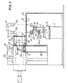
- Fig. 3 From the side view of Fig. 3 it follows that the horizontal slide 14 with the workpiece carrier 16 in a box-shaped Housing 40 is housed, one of a sliding Cover 41 opening 42 to be closed in the top wall having. Through the opening 42, a loading device 43 are lowered, the two crankshafts to be machined 10b and 10c in horizontal juxtaposed form contains.
- the holder 19 is used to hold the new crankshafts pivoted about the horizontal axis 18 so that the jigs 20.20a for the two crankshafts that normally lie vertically one above the other, now horizontally next to each other lie.
- the transfer device 43 By lowering the transfer device 43 the crankshafts 10b, 10c to the jigs Passed 20.20a. Then the holder 19 is vertical again Position swung back.
- the tool magazine 32nd is arranged outside the housing 40.
- the headstock 24 passes through the opening 42 beyond the top wall 40 to the height of the tool magazine 32 raised so that the tool magazine 32 laterally to the Spindles 25, 25a or the drill bush holders 28, 28a are brought up can be.
- FIG. 4 shows the headstock 24 in the raised state, So during the tool change at the level of Tool magazine 32. Then the headstock 24 in the dotted position and then shut down the opening 42 is closed with the lid 41. Conveniently, a second opening is provided that is independent from opening 42 serves to move the headstock in the tool change position. This second opening has its own second cover.
- the Workpiece processing takes place in the closed housing 40, to avoid contamination of the environment by drilling fluid. After finishing the workpiece machining, the workpiece carrier becomes pivoted about the axis 18 so that the workpieces taken over by the transfer device and lying side by side can be lifted out of the opening 42.
- Fig. 5 shows the top view of the machine tool during the Workpiece machining.
- the crankshaft moves in a controlled manner and if necessary by a controlled rotary drive 44 or 44a about its longitudinal axis rotated and thereby again angularly positioned to a to be able to produce other inclined bores.
- the drill bushing 27 against the crankshaft 10 set and during the drilling process the headstock 24 advanced in the Z direction.
- the turntable 15 turned back to its neutral position and the holder 19 3 from the vertical machining position in the horizontal workpiece change position swiveled up. Then the machined crankshafts 10, 10a through the opening 42 removed through.
Landscapes
- Engineering & Computer Science (AREA)
- Mechanical Engineering (AREA)
- Drilling And Boring (AREA)
- Shafts, Cranks, Connecting Bars, And Related Bearings (AREA)
- Turning (AREA)
Claims (8)
- Machine-outil pour l'usinage de vilebrequins comprenantcaractérisée en ce queun boítier à broches (24) qui comporte au moins deux broches (25, 25a) entraínant un outil (26, 26a) etun porte-pièce (16) avec deux dispositifs de serrage (20, 21) pour maintenir deux vilebrequins (10a, 10b), le porte-pièce (16) pouvant pivoter de manière à ce que l'axe longitudinal des vilebrequins fixés par serrage s'étende selon un angle aigu par rapport à l'axe des broches (25, 25a)
le porte-pièce (16) porte les vilebrequins avec des axes longitudinaux s'étendant à l'horizontale, est disposé sur un plateau rotatif (15) pouvant pivoter autour d'un axe (A) vertical et comporte un support (19) pouvant pivoter autour d'un axe horizontal (18), sur lequel les dispositifs de serrage (20) sont disposés l'un au-dessus de l'autre et qui peut pivoter d'une position verticale à une position horizontale pour le remplacement des pièces (10,10a). - Machine-outil selon la revendication 1, caractérisée en ce que le plateau rotatif (15) est porté par un chariot horizontal (14) mobile horizontalement de manière contrôlée.
- Machine-outil selon la revendication 1 ou 2, caractérisée en ce que le boítier à broches (24) est monté sur un chariot vertical (22) pouvant se déplacer dans la direction de l'axe de la broche, lequel chariot vertical peut être piloté sur un montant fixe (12) entre une position de travail et une position de levage, et en ce qu'un chargeur d'outils (32) est disposé à la hauteur de la position de levage pour un transfert direct des outils depuis et vers la broche (25, 25a).
- Machine-outil selon la revendication 3, caractérisée en ce que le chargeur d'outils (32) comporte au moins un chargeur rotatif (33, 34) qui peut se déplacer à l'horizontale transversalement à l'axe longitudinal de la broche (25, 25a).
- Machine-outil selon l'une quelconque des revendications 1 à 4, caractérisée en ce que le boítier à broches (24) ou le chariot vertical (22) comporte pour chaque broche (25, 25a) une tige porte-canon de perçage (29, 29a) associée qui porte un canon de perçage (27,27a) amovible et qui peut être déplacée dans la direction longitudinale indépendamment de la broche correspondante (25, 25a).
- Machine-outil selon l'une quelconque des revendications 1 à 5, caractérisée en ce qu'il est prévu un chargeur d'outils (32) qui comporte dans différents plans un premier chargeur rotatif (33) pour des outils et un deuxième chargeur rotatif (34) pour des canons de perçage.
- Machine-outil selon la revendication 6, caractérisée en ce que les deux chargeurs rotatifs (33, 34) sont entraínés séparément, indépendamment l'un de l'autre, de manière à ce que différents outils (26) puissent être alignés avec le même canon de perçage (27).
- Machine-outil selon la revendication 6 ou 7, caractérisée en ce qu'il est prévu un couvercle de boítier (41) qui ferme une ouverture (42) à travers laquelle les outils (26, 26a) faisant saillie depuis le boítier à broches (24) peuvent être levés à la hauteur du chargeur d'outils (32) afin de procéder à un changement d'outil.
Applications Claiming Priority (2)
| Application Number | Priority Date | Filing Date | Title |
|---|---|---|---|
| DE29907963U DE29907963U1 (de) | 1999-05-05 | 1999-05-05 | Werkzeugmaschine zum Bearbeiten von Kurbelwellen |
| DE29907963U | 1999-05-05 |
Publications (3)
| Publication Number | Publication Date |
|---|---|
| EP1052048A1 EP1052048A1 (fr) | 2000-11-15 |
| EP1052048A8 EP1052048A8 (fr) | 2001-07-11 |
| EP1052048B1 true EP1052048B1 (fr) | 2004-06-23 |
Family
ID=8073133
Family Applications (1)
| Application Number | Title | Priority Date | Filing Date |
|---|---|---|---|
| EP00108744A Expired - Lifetime EP1052048B1 (fr) | 1999-05-05 | 2000-04-22 | Machine outil pour l'usinage des vilebrequins |
Country Status (5)
| Country | Link |
|---|---|
| US (1) | US6228007B1 (fr) |
| EP (1) | EP1052048B1 (fr) |
| AT (1) | ATE269771T1 (fr) |
| DE (2) | DE29907963U1 (fr) |
| ES (1) | ES2223339T3 (fr) |
Families Citing this family (41)
| Publication number | Priority date | Publication date | Assignee | Title |
|---|---|---|---|---|
| ES2167146B1 (es) * | 1999-04-19 | 2003-11-01 | Etxetar Sa | Maquina para taladrar agujeros de engrase en cigueñales y procedimiento correspondiente. |
| DE19938856A1 (de) | 1999-08-17 | 2001-02-22 | Tiefbohrtechnik Gmbh Tbt | Tiefbohreinrichtung |
| US6506143B1 (en) * | 1999-10-05 | 2003-01-14 | Honda Giken Kogyo Kabushiki Kaisha | Apparatus for finishing inside diameter of work |
| DE10034776B4 (de) * | 2000-07-18 | 2009-09-10 | Mag Maintenance Technologies Gmbh | Vorrichtung zum Erzeugen von schrägen Tieflochbohrungen in metallischen Werkstücken mit konvexer Oberfläche |
| FR2832661B1 (fr) * | 2001-11-26 | 2004-03-12 | Airbus France | Unite de prehension pour l'usinage automatise de pieces, et dispositif et procede d'usinage integrant une telle unite |
| DE10160037A1 (de) * | 2001-12-03 | 2003-08-28 | Tiefbohrtechnik Gmbh Tbt | Tiefbohreinrichtung |
| DE10208572A1 (de) | 2002-02-21 | 2003-09-11 | Ex Cell O Gmbh | Werkzeugmaschine |
| DE102004009513B4 (de) * | 2004-02-27 | 2008-04-10 | Emag Holding Gmbh | Verfahren und Vorrichtung zum Tiefbohren von Werkstücken, insbesondere Kurbelwellen |
| DE102004036371C5 (de) * | 2004-07-23 | 2008-10-30 | Starragheckert Gmbh | Vorrichtung für die Mehrseitenbearbeitung von Werkstücken |
| US7588397B2 (en) * | 2005-08-31 | 2009-09-15 | Ingersoll Cm Systems Llc | Method and apparatus for machining crankshafts or camshafts |
| DE102005043399B4 (de) * | 2005-09-08 | 2009-06-10 | Tixbo Tiefbohr-Center Gmbh & Co.Kg | Vorrichtung zur spanenden Bearbeitung mit automatischem Werkzeugwechsel sowie Verfahren zum automatischen Wechseln von Werkzeugen an der Vorrichtung zur spanenden Bearbeitung |
| ITTO20050765A1 (it) * | 2005-10-27 | 2007-04-28 | Biesse Spa | Centro di lavoro a controllo numerico per lastre di vetro, pietra, marmo o simili, con due o piu' teste di lavorazione |
| US20090194497A1 (en) * | 2008-02-03 | 2009-08-06 | Cheng-Feng Lin | Gantry with a Buffering Structure |
| IT1398614B1 (it) * | 2009-08-05 | 2013-03-08 | Camozzi Machine Tools S P A Ora Innse Berardi S P A | Macchina combinata per barenatura e fresa- alesatura |
| US8784155B2 (en) * | 2011-05-16 | 2014-07-22 | Huaizhong Guo | Multi-carriage symmetrical numerically controlled coordinate grinding machine |
| EP2722119B1 (fr) * | 2011-06-17 | 2015-09-02 | Etxe-Tar, S.A. | Machine et procédé d'usinage de vilebrequins |
| ITTV20120043A1 (it) * | 2012-03-21 | 2013-09-22 | Almerino Canuto | Dispositivo di cambio punte a cannone per forature profonde |
| EP2929979A1 (fr) * | 2014-04-08 | 2015-10-14 | Etxe-Tar, S.A. | Machine-outil pour l'usinage de barres de connexion |
| CN105081967A (zh) * | 2014-05-20 | 2015-11-25 | 湘潭三峰数控机床有限公司 | 一种用于磨床的立柱 |
| CN104084615A (zh) * | 2014-06-29 | 2014-10-08 | 柳州美纳机械有限公司 | 圆环支座的加工方法 |
| US9751166B2 (en) * | 2014-07-09 | 2017-09-05 | The Boeing Company | Apparatus and methods for manipulating a fastener |
| CN104209758B (zh) * | 2014-09-03 | 2017-06-06 | 浙江荣荣实业有限公司 | 散热片铣加工治具 |
| DE102015111468A1 (de) * | 2015-07-15 | 2017-01-19 | Gebr. Heller Maschinenfabrik Gmbh | Bearbeitungsmaschine mit neuartiger Werkstückbeladeeinrichtung |
| CN106077749B (zh) * | 2016-07-15 | 2018-04-13 | 保定标正机床有限责任公司 | 一种立式双面钻削斜孔的机床 |
| CN106141242B (zh) * | 2016-08-05 | 2018-06-05 | 湖北伟翔数控机床股份有限公司 | 数控双曲轴端面钻孔机构 |
| US10190933B2 (en) * | 2016-11-01 | 2019-01-29 | Dominion Technologies Group, Inc. | Crankshaft balancer machine |
| CN107335862B (zh) * | 2017-08-28 | 2023-06-30 | 安徽华旦机械制造有限公司 | 一种双工位铰曲轴主轴油孔设备 |
| CN107953146B (zh) * | 2017-09-28 | 2024-05-17 | 襄阳福达东康曲轴有限公司 | 曲轴加工多工序组合机床 |
| CN107866689B (zh) * | 2017-11-30 | 2024-06-25 | 内江金鸿曲轴有限公司 | 立式加工中心钻曲轴油孔通用夹具 |
| CN108247353A (zh) * | 2018-02-06 | 2018-07-06 | 深圳中科创新精密科技有限公司 | 多功能数控机床 |
| CN108555339A (zh) * | 2018-06-15 | 2018-09-21 | 重庆伟福机械有限公司 | 一种钻床 |
| WO2021028205A1 (fr) * | 2019-08-09 | 2021-02-18 | Tbt Tiefbohrtechnik Gmbh + Co | Machine de perçage en profondeur |
| KR102692125B1 (ko) * | 2019-12-03 | 2024-08-05 | 현대자동차 주식회사 | 크랭크 샤프트의 센터홈 가공 머시닝 센터 및 이를 이용한 크랭크 샤프트의 센터홈 가공 방법 |
| EP3875195A1 (fr) * | 2020-03-03 | 2021-09-08 | Välinge Innovation AB | Machine pour produire deux trous ou plus dans la surface d'une plaque |
| EP3715051B1 (fr) * | 2020-07-24 | 2024-04-03 | Fill Gesellschaft m.b.H. | Machine-outil et procédé de fonctionnement de la machine-outil |
| EP4204183B1 (fr) * | 2020-08-28 | 2026-05-06 | Etxe-Tar, S.A. | Machine-outil |
| CN114160837A (zh) * | 2021-12-21 | 2022-03-11 | 杭州江滨内燃机配件有限公司 | 一种曲臂钻孔装置及其使用方法 |
| CN114406714B (zh) * | 2022-03-03 | 2023-12-26 | 浙江奔利汽车部件有限公司 | 一种汽车减震器连杆端部自动化成型生产线 |
| JP2024164641A (ja) * | 2023-05-15 | 2024-11-27 | 株式会社スギノマシン | 横型加工機及び工具交換装置 |
| CN117620261B (zh) * | 2024-01-09 | 2025-04-22 | 三和机电股份有限公司 | 一种用于曲轴生产的钻孔设备 |
| CN119973167A (zh) * | 2025-02-28 | 2025-05-13 | 山西柴油机工业有限责任公司 | 一种曲轴深孔加工用夹具 |
Family Cites Families (54)
| Publication number | Priority date | Publication date | Assignee | Title |
|---|---|---|---|---|
| US408259A (en) | 1889-08-06 | pentz | ||
| US1752961A (en) | 1927-04-07 | 1930-04-01 | Edd C Oliver | Universal grinder |
| US2057939A (en) | 1932-12-27 | 1936-10-20 | Frank M Davis | Crankshaft drilling machine |
| US2033686A (en) | 1933-06-10 | 1936-03-10 | Davis And Thompson Company | Multiple operation machine |
| US2233993A (en) * | 1938-07-13 | 1941-03-04 | Leblond Mach Tool Co R K | Loading and unloading of work in machine tools |
| US2310870A (en) | 1939-04-15 | 1943-02-09 | Retterath Valentin | Radial drilling machine |
| US2408491A (en) | 1943-11-24 | 1946-10-01 | Albert F Wall | Work holding fixture |
| NL69637C (fr) | 1945-12-12 | |||
| US2963944A (en) | 1956-08-30 | 1960-12-13 | Cincinnati Mfg Corp | Convertible milling machine |
| CH365598A (de) | 1958-12-08 | 1962-11-15 | Zink Karl | Mehrzweck-Werkzeugmaschine |
| US3095767A (en) | 1961-05-15 | 1963-07-02 | Jesonis Alexander | Apparatus and method for drilling holes |
| US3232141A (en) | 1961-12-26 | 1966-02-01 | Sundstrand Corp | Machine tool |
| BE628534A (fr) | 1962-02-17 | |||
| US3189065A (en) * | 1962-05-01 | 1965-06-15 | Cochrane Furniture Co Inc | Multiple drilling apparatus |
| US3382740A (en) | 1965-12-29 | 1968-05-14 | Russell P. Lotta | Ball drilling machine |
| GB1210914A (en) * | 1966-11-11 | 1970-11-04 | Herbert Ltd A | Machine tools provided with automatic tool change facilities |
| US3577828A (en) | 1969-04-17 | 1971-05-04 | Gulf & Western Precision Engin | Milling machine |
| DE1962484A1 (de) | 1969-12-12 | 1971-11-04 | Friedrich Deckel Praez S Mecha | Werkzeugmaschine mit in einer auf deren Staender angeordneten Schraegfuehrung einstellbarem Schraegschlitten |
| US3841783A (en) | 1971-02-08 | 1974-10-15 | Mero Ag | Apparatus for the production of connectors for space frameworks or the like |
| US3841782A (en) | 1971-02-08 | 1974-10-15 | Mero Ag | Apparatus for the production of connectors for space frameworks or the like |
| US3850540A (en) | 1971-02-08 | 1974-11-26 | Mero Ag | Apparatus for the production of connectors for space frameworks or the like |
| US3841784A (en) | 1971-02-08 | 1974-10-15 | Mero Ag | Apparatus for the production of connectors for space frameworks or the like |
| CH531394A (fr) | 1971-08-04 | 1972-12-15 | Genevoise Instr Physique | Appareil diviseur à plateau rotatif inclinable, pour machine-outil |
| US3782847A (en) | 1971-12-29 | 1974-01-01 | L Kulzer | Method and apparatus for reconditioning cylinder heads |
| US3806691A (en) * | 1972-11-20 | 1974-04-23 | Cammann Mfg Co | Tool positioner |
| FR2290981A1 (fr) | 1974-07-01 | 1976-06-11 | Romeu Ramon | Fraiseuse universelle |
| SE423195B (sv) | 1977-05-04 | 1982-04-26 | Per Olof Aldrin | Verktygsmaskin av universaltyp |
| US4369958A (en) | 1980-11-17 | 1983-01-25 | Airco, Inc. | Rotating table positioning device with minimum backlash |
| US4655652A (en) | 1982-02-03 | 1987-04-07 | The O.S. Kelly Company | Method of multiple station drilling |
| JPS58165950A (ja) * | 1982-03-24 | 1983-10-01 | Hitachi Seiki Co Ltd | マシニングセンタのカバ−自動開閉装置 |
| DE3220026A1 (de) | 1982-05-27 | 1983-12-01 | Maho Werkzeugmaschbau Babel | Teilapparat |
| JPS59232707A (ja) * | 1983-05-26 | 1984-12-27 | Honda Motor Co Ltd | クランク軸の油孔加工装置 |
| US4624610A (en) * | 1983-06-27 | 1986-11-25 | J. D. Phillips Corporation | Milling machine |
| FR2556627B1 (fr) | 1983-12-16 | 1990-10-12 | Honda Motor Co Ltd | Perceuse |
| FR2560541B1 (fr) | 1984-03-02 | 1987-06-26 | Sateco Sarl | Machine executant diverses operations d'usinage, telles que tournage, fraisage, alesage |
| US4589174A (en) | 1984-03-27 | 1986-05-20 | Brigham Young University | Polar coordinate apparatus |
| US4604787A (en) | 1984-08-15 | 1986-08-12 | Transamerica Delaval Inc. | Tool changer for manipulator arm |
| JPS6179508A (ja) | 1984-09-28 | 1986-04-23 | Komatsu Ltd | 数値制御式斜面加工方法 |
| DE3735858A1 (de) | 1987-10-23 | 1989-05-03 | Chiron Werke Gmbh | Vorrichtung zum einbringen von befestigungsbohrungen oder ventilbohrungen in eine schuessel bzw. eine felge eines rades eines kraftfahrzeuges |
| JP2719921B2 (ja) | 1988-03-10 | 1998-02-25 | 株式会社マキシンコー | フェースギャの歯形、該歯形の創成加工方法及び該歯形を利用した差動減速装置 |
| JPH01264732A (ja) | 1988-04-12 | 1989-10-23 | Kitamura Mach Co Ltd | 工作機械 |
| US5028180A (en) | 1989-09-01 | 1991-07-02 | Sheldon Paul C | Six-axis machine tool |
| US4988244A (en) | 1989-09-01 | 1991-01-29 | Kearney & Trecker | Six-axis machine tool |
| JPH0457635A (ja) | 1990-06-25 | 1992-02-25 | Kitamura Mach Co Ltd | 工作機械 |
| JP2764467B2 (ja) * | 1990-11-01 | 1998-06-11 | キタムラ機械株式会社 | 多面型ツールマガジン |
| DE4307482A1 (de) * | 1993-03-10 | 1994-09-22 | Max Rhodius Gmbh | Werkzeugmaschine |
| KR100351309B1 (ko) * | 1993-09-21 | 2002-12-06 | 가부시키가이샤 나카노한킹 | 공작기계용슬라이드커버장치 |
| US5427478A (en) | 1993-09-30 | 1995-06-27 | John N. Boucher | Bowling ball drilling apparatus |
| US5391850A (en) | 1994-01-28 | 1995-02-21 | Ford Motor Company | Apparatus and method for fast hole drilling by electrical discharge machining |
| DE19510498C2 (de) * | 1995-03-23 | 1998-07-23 | Heckert Chemn Werkzeugmasch | Werkzeugwechseleinrichtung mit einem aus mehreren Teilspeichern bestehenden Werkzeuspeicher |
| US5759140A (en) | 1995-04-19 | 1998-06-02 | Ingersoll Cm Systems, Inc. | Method and apparatus for machining holes in crankshafts |
| US5699599A (en) | 1996-04-04 | 1997-12-23 | Zieve; Peter B. | Multiple axis yoke for large scale workpiece assembly systems |
| FR2748225B1 (fr) * | 1996-05-03 | 1998-07-31 | Renault Automation | Dispositif d'emmagasinage des outils d'une machine-outil d'usinage |
| US6082939A (en) * | 1998-07-09 | 2000-07-04 | Toyoda Koki Kabushiki Kaisha | Machine tool and cover apparatus therefor |
-
1999
- 1999-05-05 DE DE29907963U patent/DE29907963U1/de not_active Expired - Lifetime
- 1999-11-03 US US09/432,225 patent/US6228007B1/en not_active Expired - Fee Related
-
2000
- 2000-04-22 EP EP00108744A patent/EP1052048B1/fr not_active Expired - Lifetime
- 2000-04-22 AT AT00108744T patent/ATE269771T1/de not_active IP Right Cessation
- 2000-04-22 ES ES00108744T patent/ES2223339T3/es not_active Expired - Lifetime
- 2000-04-22 DE DE50006868T patent/DE50006868D1/de not_active Expired - Lifetime
Also Published As
| Publication number | Publication date |
|---|---|
| DE50006868D1 (de) | 2004-07-29 |
| US6228007B1 (en) | 2001-05-08 |
| EP1052048A8 (fr) | 2001-07-11 |
| EP1052048A1 (fr) | 2000-11-15 |
| DE29907963U1 (de) | 1999-07-29 |
| ES2223339T3 (es) | 2005-03-01 |
| ATE269771T1 (de) | 2004-07-15 |
Similar Documents
| Publication | Publication Date | Title |
|---|---|---|
| EP1052048B1 (fr) | Machine outil pour l'usinage des vilebrequins | |
| EP1204504B1 (fr) | Dispositif de percage profond | |
| DE69602079T2 (de) | Werkzeugmaschine mit horizontalen spindeln | |
| DE69907283T2 (de) | Maschine zum bohren von öllöchern in kurbelwellen und dessen methode | |
| DE68909889T2 (de) | Werkzeugmaschine für mehrere bearbeitungsarten und zur komplexen bearbeitung von langen werkstücken. | |
| DE19533320C2 (de) | Rundtaktmaschine | |
| DE102017208318B4 (de) | Werkstückklemmvorrichtung | |
| DE102004050035A1 (de) | Werkzeugmaschine und Verfahren zum Werkzeugwechsel an einer Werkzeugmaschine | |
| DE19919645A1 (de) | Werkzeugmaschine mit Werkzeugspindel und Revolverkopf | |
| EP0310128A2 (fr) | Système de changement d'outils | |
| DE10307977C5 (de) | Verfahren und Vorrichtung zur Bearbeitung von Ausgleichsgehäusen | |
| DE3544192A1 (de) | Automatische bearbeitungseinrichtung | |
| DE3317305A1 (de) | Holzbearbeitungsmaschinen | |
| EP0260692B1 (fr) | Machine-outil avec un porte-broche à forer et à fraiser à déplacement dans la direction Z sur un châssis de machine | |
| WO2021028205A1 (fr) | Machine de perçage en profondeur | |
| DE102004013069A1 (de) | Werkzeugmaschine und Verfahren zum Bearbeiten eines Werkstücks | |
| DE102019211997A1 (de) | Tiefbohrmaschine | |
| EP2762253B1 (fr) | Machine-outil destinée au traitement de pièces à usiner | |
| DE112016000945T5 (de) | Schwingungsdämpfervorrichtung | |
| DE102006042006B4 (de) | Drehmaschine | |
| EP0949029B1 (fr) | Machine outil pour l'usinage des barres | |
| DE19911156A1 (de) | Drehmaschine, insbesondere zur Bearbeitung von wellenförmigen Werkstücken | |
| DE202019104405U1 (de) | Tiefbohrmaschine | |
| DE3544174A1 (de) | Automatische bearbeitungsmaschine mit einer werkstuecktransfereinrichtung | |
| DE202019104054U1 (de) | Tiefbohrmaschine |
Legal Events
| Date | Code | Title | Description |
|---|---|---|---|
| PUAI | Public reference made under article 153(3) epc to a published international application that has entered the european phase |
Free format text: ORIGINAL CODE: 0009012 |
|
| AK | Designated contracting states |
Kind code of ref document: A1 Designated state(s): AT BE CH CY DE DK ES FI FR GB GR IE IT LI LU MC NL PT SE |
|
| AX | Request for extension of the european patent |
Free format text: AL;LT;LV;MK;RO;SI |
|
| 17P | Request for examination filed |
Effective date: 20010510 |
|
| RIN1 | Information on inventor provided before grant (corrected) |
Inventor name: QUAK, ANDREAS |
|
| RIN1 | Information on inventor provided before grant (corrected) |
Inventor name: QUAK, ANDREAS Inventor name: DEY, HANS-JOACHIM |
|
| AKX | Designation fees paid |
Free format text: AT BE CH CY DE DK ES FI FR GB GR IE IT LI LU MC NL PT SE |
|
| 17Q | First examination report despatched |
Effective date: 20030227 |
|
| GRAP | Despatch of communication of intention to grant a patent |
Free format text: ORIGINAL CODE: EPIDOSNIGR1 |
|
| GRAS | Grant fee paid |
Free format text: ORIGINAL CODE: EPIDOSNIGR3 |
|
| GRAA | (expected) grant |
Free format text: ORIGINAL CODE: 0009210 |
|
| AK | Designated contracting states |
Kind code of ref document: B1 Designated state(s): AT BE CH CY DE DK ES FI FR GB GR IE IT LI LU MC NL PT SE |
|
| PG25 | Lapsed in a contracting state [announced via postgrant information from national office to epo] |
Ref country code: NL Free format text: LAPSE BECAUSE OF FAILURE TO SUBMIT A TRANSLATION OF THE DESCRIPTION OR TO PAY THE FEE WITHIN THE PRESCRIBED TIME-LIMIT Effective date: 20040623 Ref country code: FI Free format text: LAPSE BECAUSE OF FAILURE TO SUBMIT A TRANSLATION OF THE DESCRIPTION OR TO PAY THE FEE WITHIN THE PRESCRIBED TIME-LIMIT Effective date: 20040623 Ref country code: IE Free format text: LAPSE BECAUSE OF FAILURE TO SUBMIT A TRANSLATION OF THE DESCRIPTION OR TO PAY THE FEE WITHIN THE PRESCRIBED TIME-LIMIT Effective date: 20040623 Ref country code: FR Free format text: LAPSE BECAUSE OF FAILURE TO SUBMIT A TRANSLATION OF THE DESCRIPTION OR TO PAY THE FEE WITHIN THE PRESCRIBED TIME-LIMIT Effective date: 20040623 |
|
| REG | Reference to a national code |
Ref country code: GB Ref legal event code: FG4D Free format text: NOT ENGLISH |
|
| REG | Reference to a national code |
Ref country code: CH Ref legal event code: EP |
|
| REG | Reference to a national code |
Ref country code: IE Ref legal event code: FG4D Free format text: GERMAN |
|
| REF | Corresponds to: |
Ref document number: 50006868 Country of ref document: DE Date of ref document: 20040729 Kind code of ref document: P |
|
| PG25 | Lapsed in a contracting state [announced via postgrant information from national office to epo] |
Ref country code: DK Free format text: LAPSE BECAUSE OF FAILURE TO SUBMIT A TRANSLATION OF THE DESCRIPTION OR TO PAY THE FEE WITHIN THE PRESCRIBED TIME-LIMIT Effective date: 20040923 Ref country code: GR Free format text: LAPSE BECAUSE OF FAILURE TO SUBMIT A TRANSLATION OF THE DESCRIPTION OR TO PAY THE FEE WITHIN THE PRESCRIBED TIME-LIMIT Effective date: 20040923 |
|
| REG | Reference to a national code |
Ref country code: SE Ref legal event code: TRGR |
|
| GBT | Gb: translation of ep patent filed (gb section 77(6)(a)/1977) |
Effective date: 20040916 |
|
| NLV1 | Nl: lapsed or annulled due to failure to fulfill the requirements of art. 29p and 29m of the patents act | ||
| REG | Reference to a national code |
Ref country code: ES Ref legal event code: FG2A Ref document number: 2223339 Country of ref document: ES Kind code of ref document: T3 |
|
| REG | Reference to a national code |
Ref country code: IE Ref legal event code: FD4D |
|
| PG25 | Lapsed in a contracting state [announced via postgrant information from national office to epo] |
Ref country code: IT Free format text: LAPSE BECAUSE OF NON-PAYMENT OF DUE FEES Effective date: 20050422 Ref country code: CY Free format text: LAPSE BECAUSE OF FAILURE TO SUBMIT A TRANSLATION OF THE DESCRIPTION OR TO PAY THE FEE WITHIN THE PRESCRIBED TIME-LIMIT Effective date: 20050422 Ref country code: AT Free format text: LAPSE BECAUSE OF NON-PAYMENT OF DUE FEES Effective date: 20050422 |
|
| PG25 | Lapsed in a contracting state [announced via postgrant information from national office to epo] |
Ref country code: ES Free format text: LAPSE BECAUSE OF NON-PAYMENT OF DUE FEES Effective date: 20050423 Ref country code: SE Free format text: LAPSE BECAUSE OF NON-PAYMENT OF DUE FEES Effective date: 20050423 |
|
| PLBE | No opposition filed within time limit |
Free format text: ORIGINAL CODE: 0009261 |
|
| STAA | Information on the status of an ep patent application or granted ep patent |
Free format text: STATUS: NO OPPOSITION FILED WITHIN TIME LIMIT |
|
| PG25 | Lapsed in a contracting state [announced via postgrant information from national office to epo] |
Ref country code: LI Free format text: LAPSE BECAUSE OF NON-PAYMENT OF DUE FEES Effective date: 20050430 Ref country code: CH Free format text: LAPSE BECAUSE OF NON-PAYMENT OF DUE FEES Effective date: 20050430 Ref country code: BE Free format text: LAPSE BECAUSE OF NON-PAYMENT OF DUE FEES Effective date: 20050430 Ref country code: MC Free format text: LAPSE BECAUSE OF NON-PAYMENT OF DUE FEES Effective date: 20050430 |
|
| 26N | No opposition filed |
Effective date: 20050324 |
|
| EN | Fr: translation not filed | ||
| BERE | Be: lapsed |
Owner name: *HONSBERG LAMB SONDERWERKZEUGMASCHINEN G.M.B.H. Effective date: 20050430 |
|
| EUG | Se: european patent has lapsed | ||
| REG | Reference to a national code |
Ref country code: CH Ref legal event code: PL |
|
| REG | Reference to a national code |
Ref country code: ES Ref legal event code: FD2A Effective date: 20050423 |
|
| BERE | Be: lapsed |
Owner name: *HONSBERG LAMB SONDERWERKZEUGMASCHINEN G.M.B.H. Effective date: 20050430 |
|
| PG25 | Lapsed in a contracting state [announced via postgrant information from national office to epo] |
Ref country code: PT Free format text: LAPSE BECAUSE OF NON-PAYMENT OF DUE FEES Effective date: 20041123 |
|
| PGFP | Annual fee paid to national office [announced via postgrant information from national office to epo] |
Ref country code: GB Payment date: 20090424 Year of fee payment: 10 |
|
| GBPC | Gb: european patent ceased through non-payment of renewal fee |
Effective date: 20100422 |
|
| PG25 | Lapsed in a contracting state [announced via postgrant information from national office to epo] |
Ref country code: GB Free format text: LAPSE BECAUSE OF NON-PAYMENT OF DUE FEES Effective date: 20100422 |
|
| PGFP | Annual fee paid to national office [announced via postgrant information from national office to epo] |
Ref country code: DE Payment date: 20120622 Year of fee payment: 13 |
|
| PG25 | Lapsed in a contracting state [announced via postgrant information from national office to epo] |
Ref country code: DE Free format text: LAPSE BECAUSE OF NON-PAYMENT OF DUE FEES Effective date: 20131101 |
|
| REG | Reference to a national code |
Ref country code: DE Ref legal event code: R119 Ref document number: 50006868 Country of ref document: DE Effective date: 20131101 |