EP1052049B1 - Méthode et appareil pour l'usinage avec enlèvement de copeaux - Google Patents
Méthode et appareil pour l'usinage avec enlèvement de copeaux Download PDFInfo
- Publication number
- EP1052049B1 EP1052049B1 EP00890138A EP00890138A EP1052049B1 EP 1052049 B1 EP1052049 B1 EP 1052049B1 EP 00890138 A EP00890138 A EP 00890138A EP 00890138 A EP00890138 A EP 00890138A EP 1052049 B1 EP1052049 B1 EP 1052049B1
- Authority
- EP
- European Patent Office
- Prior art keywords
- tool
- workpiece
- machining
- bearing
- cutting edge
- Prior art date
- Legal status (The legal status is an assumption and is not a legal conclusion. Google has not performed a legal analysis and makes no representation as to the accuracy of the status listed.)
- Expired - Lifetime
Links
- 238000003754 machining Methods 0.000 title claims abstract description 24
- 238000000034 method Methods 0.000 title claims description 16
- 238000005520 cutting process Methods 0.000 claims abstract description 33
- 238000003801 milling Methods 0.000 claims abstract description 23
- 238000007514 turning Methods 0.000 claims abstract description 21
- 238000004519 manufacturing process Methods 0.000 claims description 6
- 230000010355 oscillation Effects 0.000 claims description 4
- 238000006073 displacement reaction Methods 0.000 claims 1
- 238000000465 moulding Methods 0.000 claims 1
- 230000007704 transition Effects 0.000 description 3
- 230000007423 decrease Effects 0.000 description 2
- 238000005516 engineering process Methods 0.000 description 2
- 238000000227 grinding Methods 0.000 description 2
- 230000000977 initiatory effect Effects 0.000 description 2
- 238000003860 storage Methods 0.000 description 2
- 208000012886 Vertigo Diseases 0.000 description 1
- 230000002411 adverse Effects 0.000 description 1
- 230000007547 defect Effects 0.000 description 1
- 230000002349 favourable effect Effects 0.000 description 1
- 239000002245 particle Substances 0.000 description 1
- 230000002093 peripheral effect Effects 0.000 description 1
- 238000007781 pre-processing Methods 0.000 description 1
- 238000007493 shaping process Methods 0.000 description 1
Images
Classifications
-
- B—PERFORMING OPERATIONS; TRANSPORTING
- B23—MACHINE TOOLS; METAL-WORKING NOT OTHERWISE PROVIDED FOR
- B23D—PLANING; SLOTTING; SHEARING; BROACHING; SAWING; FILING; SCRAPING; LIKE OPERATIONS FOR WORKING METAL BY REMOVING MATERIAL, NOT OTHERWISE PROVIDED FOR
- B23D37/00—Broaching machines or broaching devices
- B23D37/005—Broaching machines or broaching devices for cylindrical workpieces, e.g. crankshafts
-
- B—PERFORMING OPERATIONS; TRANSPORTING
- B23—MACHINE TOOLS; METAL-WORKING NOT OTHERWISE PROVIDED FOR
- B23B—TURNING; BORING
- B23B5/00—Turning-machines or devices specially adapted for particular work; Accessories specially adapted therefor
- B23B5/18—Turning-machines or devices specially adapted for particular work; Accessories specially adapted therefor for turning crankshafts, eccentrics, or cams, e.g. crankpin lathes
-
- B—PERFORMING OPERATIONS; TRANSPORTING
- B23—MACHINE TOOLS; METAL-WORKING NOT OTHERWISE PROVIDED FOR
- B23C—MILLING
- B23C3/00—Milling particular work; Special milling operations; Machines therefor
- B23C3/06—Milling crankshafts
-
- B—PERFORMING OPERATIONS; TRANSPORTING
- B23—MACHINE TOOLS; METAL-WORKING NOT OTHERWISE PROVIDED FOR
- B23C—MILLING
- B23C5/00—Milling-cutters
- B23C5/02—Milling-cutters characterised by the shape of the cutter
- B23C5/08—Disc-type cutters
-
- B—PERFORMING OPERATIONS; TRANSPORTING
- B23—MACHINE TOOLS; METAL-WORKING NOT OTHERWISE PROVIDED FOR
- B23C—MILLING
- B23C5/00—Milling-cutters
- B23C5/16—Milling-cutters characterised by physical features other than shape
- B23C5/20—Milling-cutters characterised by physical features other than shape with removable cutter bits or teeth or cutting inserts
-
- B—PERFORMING OPERATIONS; TRANSPORTING
- B23—MACHINE TOOLS; METAL-WORKING NOT OTHERWISE PROVIDED FOR
- B23C—MILLING
- B23C2210/00—Details of milling cutters
- B23C2210/28—Arrangement of teeth
- B23C2210/285—Cutting edges arranged at different diameters
-
- B—PERFORMING OPERATIONS; TRANSPORTING
- B23—MACHINE TOOLS; METAL-WORKING NOT OTHERWISE PROVIDED FOR
- B23C—MILLING
- B23C2215/00—Details of workpieces
- B23C2215/20—Crankshafts
-
- G—PHYSICS
- G10—MUSICAL INSTRUMENTS; ACOUSTICS
- G10L—SPEECH ANALYSIS TECHNIQUES OR SPEECH SYNTHESIS; SPEECH RECOGNITION; SPEECH OR VOICE PROCESSING TECHNIQUES; SPEECH OR AUDIO CODING OR DECODING
- G10L19/00—Speech or audio signals analysis-synthesis techniques for redundancy reduction, e.g. in vocoders; Coding or decoding of speech or audio signals, using source filter models or psychoacoustic analysis
- G10L2019/0001—Codebooks
- G10L2019/0013—Codebook search algorithms
Definitions
- the invention relates to a method for machining, in particular for creating curved surfaces of partial areas of workpieces, For example, from bearing zones to crankshafts, in which the workpiece as well the tool is at least partially rotated and moved relative to each other.
- the invention is concerned with a device for machining Machining, in particular device for creating curved surfaces of workpieces, for example of bearing zones on crankshafts, consisting in Essentially from at least one drivable workpiece clamping device and an axparallel rotating drivable towards the workpiece back and Push-fit and adjustable tool clamping device with a disc-shaped tool, in particular for carrying out the method.
- Machined pegs of workpieces are both by turning and by a milling of the blank produced. Is a journal of a crankshaft through Machined milling, so the tool rotates with a variety of cutting edges, wherein a slow rotation of the shaft itself constitutes the feed. each The cutting edge of the tool is chipping effective, resulting in a large Cutting performance and a high efficiency of processing results. adversely however, that is, every single cutting edge engaged in succession Reason of the feed a chip from the workpiece decreases and thereby its cut surface receives a grooves having structure. Such Surface scans are meaningless when, for example, below Grinding the machining areas is made or if the grooves, due to a low mechanical stress of these areas of the workpiece in practical use, no risk of crack initiation.
- a tool change and a re-clamping of the workpiece are also the Dimensional accuracy due to elaborate operations that require time, so in the Processing technology, in particular for a cutting shaping of Crankshafts, economical solutions for milling and subsequently turning certain areas of a workpiece are searched.
- the invention seeks to remedy the situation and sets itself the goal of a procedure specify with which a cost-effective creation of curved Surfaces with at least partial areas with improved quality can be produced.
- the object is achieved by a method according to claim 1 and an apparatus according to claim 6.
- the bearing surfaces of the crankshaft by at least one inclined Tool edge are istspant by Drehconss, with a Nachfelden the Tool depending on the edge slope related to the Lageraxe
- the further object of the invention the shortcomings of known processing machines to eliminate it achieved that the movable in the direction of the workpiece Tool clamping device with the tool as an alternative to the rotational movement for a Milling, for tracking a rotary cutting edge on the machining area controlled at an angle, oscillating pivotally or the like rotatable is trained.
- the rotary tool also at eccentric about an axis rotating machining surfaces, such as Connecting rod bearing surfaces of a crankshaft, in all cases angular, that is with Constant Span- free and attack angle can be brought into engagement.
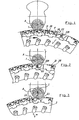
- a workpiece 1 in the present a crankshaft journal, at a Milling processing represented by a tool 2, wherein a direction of rotation D of the Tool is counterposed to that of a workpiece 1.
- Cutting body 21 with cutting corners 211 for milling, forming a circle F, by a Rotation of the tool in a sequence at a position of the same abspanend are effective, are in a peripheral region by a segment 20 with a, in the position against the tool axis or the flight circle F reset Cutting body 22 having a cutting edge 221 for a turning operation interrupted. During a milling of the workpiece enters the Cutting edge 221 not in engaged position.
- the tool 2 After a chip removal by milling, the tool 2 is in a position as shown in Fig. 2, stopped or fixed, in which a cutting body 22 with a cutting edge 221 for a turning of the workpiece. 1 is opposite.
- a cutting body 22 with a cutting edge 221 for a turning of the workpiece. 1 is opposite.
- Fig. 3 is a processing of a cylindrical surface of a workpiece 1, for Example of a pin of a crankshaft, represented by twisting spaces. Compared to a rotating workpiece while an inclined Tool cutting edge 221 by a feed V against the workpiece rotation direction each partially forming a particle.
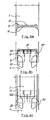
- Fig. 4a is a workpiece 1 with a contour 11 of the blank and such a 12th represented the machined part, wherein the machining contour 12 grooves 13 has.
- Fig. 4b shows the above workpiece with a by milling by means Milling cutter body 21, 21 ', 21 "swept volume range 121 with respect to a Blank surface 11.
- Cutting body 22 for a turning are in one Part of the tool circumference set back and not engaged.
- a tool 2 is positioned such that rotary body 22 and 22 'with Cutting 122 grooves 13 in a processing area of a workpiece Screw.
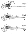
- FIG. 5 shows a milling process of a workpiece 1 or a milling of a connecting rod of a crankshaft in the direction of synchronization, which is advantageous with regard to the service life of the tool cutting edges.
- the crankshaft is clamped in such a way that it rotates about the main bearing axis B
- the connecting rod pin or its axis A performs an eccentric rotational movement which must be taken into account by a tracking movement X A of the tool.
- milling according to the invention is subsequently carried out by means of a cutting body 22, as shown in FIG. 6, then in addition to a tracking movement X A a rotating pivoting movement S of the tool 2 is made for angular adjustment of the cutting edge 221.
Landscapes
- Engineering & Computer Science (AREA)
- Mechanical Engineering (AREA)
- Milling Processes (AREA)
- Turning (AREA)
- Auxiliary Devices For Machine Tools (AREA)
- Polishing Bodies And Polishing Tools (AREA)
- Electrical Discharge Machining, Electrochemical Machining, And Combined Machining (AREA)
Claims (7)
- Méthode d'usinage avec enlèvement de copeaux, en particulier pour réaliser des surfaces incurvées usinées sur des parties de pièces, par exemple des portées de vilebrequin, dans laquelle la pièce et, au moins en partie, l'outil sont entraínés en rotation et déplacés l'un par rapport à l'autre et au moins certaines parties des zones de surface ayant subi un usinage de finition présentent une meilleure qualité et/ou une tolérance dimensionnelle plus étroite, caractérisée en ce que l'usinage se déroule en deux étapes au moyen d'un seul outil, la première étape d'usinage consistant en un enlèvement de copeaux par fraisage lors duquel la pièce et l'outil sont entraínés en rotation et mis en prise l'un avec l'autre, après quoi s'effectue, lors d'une seconde étape d'usinage, un autre enlèvement de copeaux sur des zones partielles, étant précisé que le mouvement de rotation de l'outil est alors arrêté, au moins une arête de coupe de l'outil est mise en prise avec la pièce en rotation et des copeaux de tournage sont enlevés de cette dernière, un mouvement de rotation et de pivotement de l'outil étant superposé à un mouvement de poursuite pour assurer une mise en prise angulairement correcte de l'arête de coupe.
- Méthode selon la revendication 1, caractérisée en ce que lors de la fabrication de vilebrequins, les portées sont chacune fraisées lors de la première étape d'usinage, après quoi, lors de la seconde étape d'usinage, le mouvement rotatif de l'outil est arrêté dans une position prédéfinie dans laquelle les portées ainsi que les arrondis ou congés de maneton agencés de part et d'autre de la portée sont usinés par tournage.
- Méthode selon la revendication 1 ou la revendication 2, caractérisée en ce que, lors de la seconde étape d'usinage, chacune des portées du vilebrequin est usinée par tournage-arasage au moyen d'au moins une arête d'outil oblique, un ajustement en rotation de l'outil étant effectué en fonction de l'inclinaison de l'arête par rapport à l'axe du palier.
- Méthode selon l'une des revendications 1 à 3, caractérisée en ce que, lors de la seconde étape d'usinage, les congés du vilebrequin sont ménagés par tournage-arasage au moyen de plaquettes de profilage.
- Méthode selon l'une des revendications 1 à 4, caractérisée en ce que lors de l'usinage d'une partie excentrée de la pièce entraínée en rotation, par exemple une portée de bielle d'un vilebrequin entraíné en rotation autour de l'axe du palier principal, l'outil suit de manière commandée la surface d'usinage, étant précisé que dans la seconde étape d'usinage, en fonction de la dimension de la surface à usiner et de la distance entre l'arête de coupe et l'axe de l'outil, un mouvement de pivotement oscillatoire, notamment un mouvement de rotation et de pivotement, de l'outil sur un secteur angulaire est superposé au mouvement de poursuite.
- Dispositif d'usinage par enlèvement de copeaux, en particulier dispositif pour réaliser des surfaces incurvées de pièces (1), par exemple de portées de vilebrequin, composé pour l'essentiel d'au moins un dispositif de serrage de pièce commandable et d'un dispositif de serrage d'outil apte à être entraíné en rotation parallèlement à l'axe, à être rapproché ou éloigné de la pièce (1) dans la direction (A) et à être mis en prise avec ladite pièce, doté d'un outil en forme de disque (2), notamment pour mettre en oeuvre la méthode selon les revendications précédentes, caractérisé en ce que le dispositif de serrage d'outil, qui est mobile dans la direction XA, est conçu apte à décrire avec l'outil (2) un mouvement commandé de pivotement oscillatoire ou un mouvement rotatif similaire sur un angle (S) en alternative au mouvement rotatif (D) associé à une opération de fraisage, pour qu'une arête de coupe (221) suive la zone à usiner.
- Dispositif selon la revendication 6, caractérisé en ce qu'à l'oscillation (S) de l'outil (2) autour de l'axe de serrage, on peut superposer, pour le mouvement de poursuite de l'arête de coupe (221), une translation (V) - qui est déduite de la géométrie de l'arête de coupe - de la zone d'oscillation en vue d'un tournage-arasage.
Priority Applications (2)
| Application Number | Priority Date | Filing Date | Title |
|---|---|---|---|
| AT00890138T ATE303224T1 (de) | 1999-05-03 | 2000-04-28 | Verfahren und einrichtung zur spanabhebenden bearbeitung |
| EP05016503A EP1595628B1 (fr) | 1999-05-03 | 2000-04-28 | Outil pour l'usinage avec enlèvement de copeaux |
Applications Claiming Priority (2)
| Application Number | Priority Date | Filing Date | Title |
|---|---|---|---|
| AT78899 | 1999-05-03 | ||
| AT0078899A AT410770B (de) | 1999-05-03 | 1999-05-03 | Verfahren, werkzeug und einrichtung zur spanabhebenden bearbeitung |
Related Child Applications (1)
| Application Number | Title | Priority Date | Filing Date |
|---|---|---|---|
| EP05016503A Division EP1595628B1 (fr) | 1999-05-03 | 2000-04-28 | Outil pour l'usinage avec enlèvement de copeaux |
Publications (3)
| Publication Number | Publication Date |
|---|---|
| EP1052049A2 EP1052049A2 (fr) | 2000-11-15 |
| EP1052049A3 EP1052049A3 (fr) | 2003-04-02 |
| EP1052049B1 true EP1052049B1 (fr) | 2005-08-31 |
Family
ID=3499772
Family Applications (2)
| Application Number | Title | Priority Date | Filing Date |
|---|---|---|---|
| EP00890138A Expired - Lifetime EP1052049B1 (fr) | 1999-05-03 | 2000-04-28 | Méthode et appareil pour l'usinage avec enlèvement de copeaux |
| EP05016503A Expired - Lifetime EP1595628B1 (fr) | 1999-05-03 | 2000-04-28 | Outil pour l'usinage avec enlèvement de copeaux |
Family Applications After (1)
| Application Number | Title | Priority Date | Filing Date |
|---|---|---|---|
| EP05016503A Expired - Lifetime EP1595628B1 (fr) | 1999-05-03 | 2000-04-28 | Outil pour l'usinage avec enlèvement de copeaux |
Country Status (3)
| Country | Link |
|---|---|
| EP (2) | EP1052049B1 (fr) |
| AT (3) | AT410770B (fr) |
| DE (2) | DE50011049D1 (fr) |
Cited By (1)
| Publication number | Priority date | Publication date | Assignee | Title |
|---|---|---|---|---|
| RU2811301C1 (ru) * | 2020-07-31 | 2024-01-11 | Кркк Хай-Тек Эквипмент Корпорейшн Лимитед | Комбинированный режущий инструмент для фрезерования рельсов на месте установки |
Families Citing this family (7)
| Publication number | Priority date | Publication date | Assignee | Title |
|---|---|---|---|---|
| DE10235957B4 (de) * | 2002-08-06 | 2005-01-20 | Hegenscheidt-Mfd Gmbh & Co. Kg | Verfahren zum Fertigbearbeiten von Kurbelwellen für Kraftfahrzeugmotoren |
| DE202004015343U1 (de) * | 2004-07-06 | 2005-11-17 | Kennametal Inc. | Werkzeug und Vorrichtung zur Bearbeitung von Werkstücken |
| PL2181789T3 (pl) * | 2008-10-30 | 2011-11-30 | Klingelnberg Ag | Uniwersalna trzonkowa głowica frezowa i jej zastosowanie |
| DE102009060926C5 (de) | 2009-12-28 | 2025-01-09 | Nsh Technology Gmbh | Verfahren zum Fertigbearbeiten der Lagersitze von Haupt- und Hublagern von Kurbelwellen |
| JP5672380B2 (ja) * | 2011-06-17 | 2015-02-18 | 株式会社タンガロイ | 切削インサート及び回転切削工具 |
| EP2947204B1 (fr) * | 2014-05-19 | 2017-01-11 | Mevert Maschinenbau GmbH & Co.KG | Dispositif mobile de fraisage de champignons de rails et procédé de changement de plaques de coupe dans le cadre d'un tel dispositif |
| CN111843007A (zh) * | 2020-07-31 | 2020-10-30 | 中国铁建高新装备股份有限公司 | 一种用于钢轨在线铣削的组合刀具 |
Family Cites Families (8)
| Publication number | Priority date | Publication date | Assignee | Title |
|---|---|---|---|---|
| JPS597513A (ja) * | 1982-06-30 | 1984-01-14 | Komatsu Ltd | クランクシヤフトの加工方法 |
| DE3523274C3 (de) * | 1985-06-28 | 1996-08-14 | Boehringer Werkzeugmaschinen | Verfahren und Vorrichtung zur spanenden Bearbeitung von rotationssymmetrischen Werkstückflächen durch Drehräumen |
| DE3525514A1 (de) * | 1985-07-17 | 1987-01-29 | Sitzmann & Heinlein | Verfahren und vorrichtung zum spanabhebenden bearbeiten eines sich drehenden werkstueckes |
| EP0286771A1 (fr) * | 1987-04-13 | 1988-10-19 | GFM Gesellschaft für Fertigungstechnik und Maschinenbau Gesellschaft m.b.H. | Tour |
| DE3924884C3 (de) * | 1989-07-27 | 1998-10-22 | Sandvik Gmbh | Werkzeug zum spanabhebenden Bearbeiten von Werkstücken |
| DE3930489C2 (de) * | 1989-09-12 | 1993-11-18 | Boehringer Werkzeugmaschinen | Verfahren und Werkzeugmaschine zum Fertigbearbeiten von Lagerzapfen |
| DE4119162C1 (fr) * | 1991-06-11 | 1992-05-21 | Gebr. Heller Maschinenfabrik Gmbh, 7440 Nuertingen, De | |
| DE4135681C3 (de) * | 1991-10-30 | 1999-02-11 | Heller Geb Gmbh Maschf | Verfahren zur spanenden Bearbeitung rotationssymmetrischer Werkstückflächen, insbesondere von Kurbelwellen, sowie Werkzeug zur Durchführung eines solchen Verfahrens |
-
1999
- 1999-05-03 AT AT0078899A patent/AT410770B/de not_active IP Right Cessation
-
2000
- 2000-04-28 EP EP00890138A patent/EP1052049B1/fr not_active Expired - Lifetime
- 2000-04-28 AT AT00890138T patent/ATE303224T1/de not_active IP Right Cessation
- 2000-04-28 DE DE50011049T patent/DE50011049D1/de not_active Expired - Fee Related
- 2000-04-28 DE DE50014855T patent/DE50014855D1/de not_active Expired - Fee Related
- 2000-04-28 EP EP05016503A patent/EP1595628B1/fr not_active Expired - Lifetime
- 2000-04-28 AT AT05016503T patent/ATE380616T1/de not_active IP Right Cessation
Cited By (1)
| Publication number | Priority date | Publication date | Assignee | Title |
|---|---|---|---|---|
| RU2811301C1 (ru) * | 2020-07-31 | 2024-01-11 | Кркк Хай-Тек Эквипмент Корпорейшн Лимитед | Комбинированный режущий инструмент для фрезерования рельсов на месте установки |
Also Published As
| Publication number | Publication date |
|---|---|
| EP1052049A3 (fr) | 2003-04-02 |
| EP1052049A2 (fr) | 2000-11-15 |
| ATE303224T1 (de) | 2005-09-15 |
| ATE380616T1 (de) | 2007-12-15 |
| EP1595628A1 (fr) | 2005-11-16 |
| DE50011049D1 (de) | 2005-10-06 |
| DE50014855D1 (de) | 2008-01-24 |
| ATA78899A (de) | 2002-12-15 |
| AT410770B (de) | 2003-07-25 |
| EP1595628B1 (fr) | 2007-12-12 |
Similar Documents
| Publication | Publication Date | Title |
|---|---|---|
| EP1030754B1 (fr) | Fraisage haute vitesse + tournage / brochage par tournage/ tournage - brochage par tournage | |
| EP2367656B2 (fr) | Machine-outil et procédé de fabrication de dentures | |
| DE10144649C5 (de) | Verfahren zur drallfreien spanenden Bearbeitung von rotationssymmetrischen Flächen | |
| EP0904176B1 (fr) | Procede et dispositif pour rectifier des surfaces en faux-rond de profils de cames a flancs concaves | |
| EP0772509B1 (fr) | Procede et dispositif permettant de meuler des cames a flancs concaves | |
| DE102011113757A1 (de) | Verfahren und Vorrichtung zur Fertigbearbeitung von Werkstücken | |
| EP1177067A1 (fr) | Procede de meulage de surfaces de roulement convexes et de diametres exterieurs, sur des pieces a usiner ondulees, dans un serrage, ainsi que meuleuse destinee a la mise en oeuvre de ce procede | |
| EP2709785A1 (fr) | Procédé et chaîne de production pour l'usinage d'un vilebrequin | |
| DE202016103064U1 (de) | Vorrichtung zur spanenden Bearbeitung eines rotierenden Werkstücks | |
| EP0868242B1 (fr) | Procede et dispositif de fraisage par rotation | |
| EP1052049B1 (fr) | Méthode et appareil pour l'usinage avec enlèvement de copeaux | |
| DE4329610C2 (de) | Bearbeitungszentrum für Kurbelwellen | |
| EP0885082B1 (fr) | Procede et dispositif pour usiner des logements de palier de vilebrequins | |
| EP1372906B1 (fr) | Procède et dispositif de production de poulies de transmission pour transmission variable en continu | |
| DE19626608B4 (de) | Verfahren zur spanenden Bearbeitung | |
| WO1992007686A1 (fr) | Honage a haute frequence | |
| DE10126796C5 (de) | Verfahren und Vorrichtung zum spitzenlosen Rundschleifen | |
| DE3340830C2 (fr) | ||
| DE4011715C1 (fr) | ||
| DE19546196A1 (de) | Verfahren zur spanenden Bearbeitung von zylindrischen Konturen, Vorrichtung zur Durchführung des Verfahrens und Schneideinsatz hierzu | |
| DE19502476A1 (de) | Verfahren und Werkzeugmaschine zur Herstellung von Freistichen insbesondere an Kurbelwellen | |
| DE102024134971A1 (de) | Verfahren zur Bearbeitung einer spiralförmigen Rille | |
| DD232863A5 (de) | Verfahren und vorrichtung vom hochgeschwindigkeits-profilschleifen von rotationssymmetrischen werkstuecken |
Legal Events
| Date | Code | Title | Description |
|---|---|---|---|
| PUAI | Public reference made under article 153(3) epc to a published international application that has entered the european phase |
Free format text: ORIGINAL CODE: 0009012 |
|
| AK | Designated contracting states |
Kind code of ref document: A2 Designated state(s): AT BE CH CY DE DK ES FI FR GB GR IE IT LI LU MC NL PT SE |
|
| AX | Request for extension of the european patent |
Free format text: AL;LT;LV;MK;RO;SI |
|
| RIC1 | Information provided on ipc code assigned before grant |
Free format text: 7B 23D 37/00 A, 7B 23C 3/06 B, 7B 23B 5/18 B |
|
| PUAL | Search report despatched |
Free format text: ORIGINAL CODE: 0009013 |
|
| AK | Designated contracting states |
Kind code of ref document: A3 Designated state(s): AT BE CH CY DE DK ES FI FR GB GR IE IT LI LU MC NL PT SE |
|
| AX | Request for extension of the european patent |
Extension state: AL LT LV MK RO SI |
|
| 17P | Request for examination filed |
Effective date: 20030602 |
|
| 17Q | First examination report despatched |
Effective date: 20031107 |
|
| AKX | Designation fees paid |
Designated state(s): AT DE FR GB IT |
|
| GRAP | Despatch of communication of intention to grant a patent |
Free format text: ORIGINAL CODE: EPIDOSNIGR1 |
|
| RTI1 | Title (correction) |
Free format text: METHOD AND APPARATUS FOR CHIP REMOVING MACHINING |
|
| RAP1 | Party data changed (applicant data changed or rights of an application transferred) |
Owner name: BOEHLERIT GMBH & CO.KG. |
|
| GRAS | Grant fee paid |
Free format text: ORIGINAL CODE: EPIDOSNIGR3 |
|
| GRAA | (expected) grant |
Free format text: ORIGINAL CODE: 0009210 |
|
| AK | Designated contracting states |
Kind code of ref document: B1 Designated state(s): AT DE FR GB IT |
|
| REG | Reference to a national code |
Ref country code: GB Ref legal event code: FG4D Free format text: NOT ENGLISH |
|
| REF | Corresponds to: |
Ref document number: 50011049 Country of ref document: DE Date of ref document: 20051006 Kind code of ref document: P |
|
| GBT | Gb: translation of ep patent filed (gb section 77(6)(a)/1977) |
Effective date: 20051207 |
|
| ET | Fr: translation filed | ||
| PLBI | Opposition filed |
Free format text: ORIGINAL CODE: 0009260 |
|
| PLAX | Notice of opposition and request to file observation + time limit sent |
Free format text: ORIGINAL CODE: EPIDOSNOBS2 |
|
| 26 | Opposition filed |
Opponent name: SANDVIK INTELLECTUAL PROPERTY AB Effective date: 20060529 |
|
| PLBB | Reply of patent proprietor to notice(s) of opposition received |
Free format text: ORIGINAL CODE: EPIDOSNOBS3 |
|
| PLCK | Communication despatched that opposition was rejected |
Free format text: ORIGINAL CODE: EPIDOSNREJ1 |
|
| PLBN | Opposition rejected |
Free format text: ORIGINAL CODE: 0009273 |
|
| STAA | Information on the status of an ep patent application or granted ep patent |
Free format text: STATUS: OPPOSITION REJECTED |
|
| 27O | Opposition rejected |
Effective date: 20080925 |
|
| PGFP | Annual fee paid to national office [announced via postgrant information from national office to epo] |
Ref country code: DE Payment date: 20090422 Year of fee payment: 10 Ref country code: AT Payment date: 20090416 Year of fee payment: 10 Ref country code: FR Payment date: 20090414 Year of fee payment: 10 Ref country code: IT Payment date: 20090427 Year of fee payment: 10 |
|
| PGFP | Annual fee paid to national office [announced via postgrant information from national office to epo] |
Ref country code: GB Payment date: 20090421 Year of fee payment: 10 |
|
| GBPC | Gb: european patent ceased through non-payment of renewal fee |
Effective date: 20100428 |
|
| REG | Reference to a national code |
Ref country code: FR Ref legal event code: ST Effective date: 20101230 |
|
| PG25 | Lapsed in a contracting state [announced via postgrant information from national office to epo] |
Ref country code: AT Free format text: LAPSE BECAUSE OF NON-PAYMENT OF DUE FEES Effective date: 20100428 |
|
| PG25 | Lapsed in a contracting state [announced via postgrant information from national office to epo] |
Ref country code: DE Free format text: LAPSE BECAUSE OF NON-PAYMENT OF DUE FEES Effective date: 20101103 |
|
| PG25 | Lapsed in a contracting state [announced via postgrant information from national office to epo] |
Ref country code: IT Free format text: LAPSE BECAUSE OF NON-PAYMENT OF DUE FEES Effective date: 20100428 Ref country code: GB Free format text: LAPSE BECAUSE OF NON-PAYMENT OF DUE FEES Effective date: 20100428 |
|
| PG25 | Lapsed in a contracting state [announced via postgrant information from national office to epo] |
Ref country code: FR Free format text: LAPSE BECAUSE OF NON-PAYMENT OF DUE FEES Effective date: 20100430 |