EP1052080B1 - Procédé pour déplacer une table basculante dans un dispositif de formage et de découpage de récipients moulés à partir d'une feuille thermoplastique et dispositif pour sa mise en oeuvre - Google Patents
Procédé pour déplacer une table basculante dans un dispositif de formage et de découpage de récipients moulés à partir d'une feuille thermoplastique et dispositif pour sa mise en oeuvre Download PDFInfo
- Publication number
- EP1052080B1 EP1052080B1 EP00108517A EP00108517A EP1052080B1 EP 1052080 B1 EP1052080 B1 EP 1052080B1 EP 00108517 A EP00108517 A EP 00108517A EP 00108517 A EP00108517 A EP 00108517A EP 1052080 B1 EP1052080 B1 EP 1052080B1
- Authority
- EP
- European Patent Office
- Prior art keywords
- fulcrum
- gravity
- pivot table
- centre
- pivot
- Prior art date
- Legal status (The legal status is an assumption and is not a legal conclusion. Google has not performed a legal analysis and makes no representation as to the accuracy of the status listed.)
- Expired - Lifetime
Links
Images
Classifications
-
- B—PERFORMING OPERATIONS; TRANSPORTING
- B29—WORKING OF PLASTICS; WORKING OF SUBSTANCES IN A PLASTIC STATE IN GENERAL
- B29C—SHAPING OR JOINING OF PLASTICS; SHAPING OF MATERIAL IN A PLASTIC STATE, NOT OTHERWISE PROVIDED FOR; AFTER-TREATMENT OF THE SHAPED PRODUCTS, e.g. REPAIRING
- B29C51/00—Shaping by thermoforming, i.e. shaping sheets or sheet like preforms after heating, e.g. shaping sheets in matched moulds or by deep-drawing; Apparatus therefor
- B29C51/26—Component parts, details or accessories; Auxiliary operations
- B29C51/261—Handling means, e.g. transfer means, feeding means
-
- B—PERFORMING OPERATIONS; TRANSPORTING
- B29—WORKING OF PLASTICS; WORKING OF SUBSTANCES IN A PLASTIC STATE IN GENERAL
- B29C—SHAPING OR JOINING OF PLASTICS; SHAPING OF MATERIAL IN A PLASTIC STATE, NOT OTHERWISE PROVIDED FOR; AFTER-TREATMENT OF THE SHAPED PRODUCTS, e.g. REPAIRING
- B29C51/00—Shaping by thermoforming, i.e. shaping sheets or sheet like preforms after heating, e.g. shaping sheets in matched moulds or by deep-drawing; Apparatus therefor
- B29C51/26—Component parts, details or accessories; Auxiliary operations
- B29C51/44—Removing or ejecting moulded articles
-
- B—PERFORMING OPERATIONS; TRANSPORTING
- B29—WORKING OF PLASTICS; WORKING OF SUBSTANCES IN A PLASTIC STATE IN GENERAL
- B29C—SHAPING OR JOINING OF PLASTICS; SHAPING OF MATERIAL IN A PLASTIC STATE, NOT OTHERWISE PROVIDED FOR; AFTER-TREATMENT OF THE SHAPED PRODUCTS, e.g. REPAIRING
- B29C51/00—Shaping by thermoforming, i.e. shaping sheets or sheet like preforms after heating, e.g. shaping sheets in matched moulds or by deep-drawing; Apparatus therefor
- B29C51/04—Combined thermoforming and prestretching, e.g. biaxial stretching
Definitions
- the invention relates to a method for moving a swivel table in a Device for forming and punching out containers according to the genus of Main claim and an apparatus for performing the method.
- the vertical movement sequence of the swivel table takes place from cam disks, one cam disk for the upward movement and one cam disk for the downward movement, as well as via a toggle lever and a lever linkage. Both cams must be precisely coordinated with each other, which results in complex calculations and expensive production and precise assembly.
- the swiveling of the swiveling table takes place via a third cam disc and via a bracket which engages on the molding table.
- the pivot point of the swivel table is also the articulation point of the toggle lever and sits in a guided bearing. This means that the pivot point and thus the bearing units perform a linear movement up and down during one cycle. In terms of energy, this has the consequence that the toggle lever drive does a corresponding job with each stroke and that work has to be destroyed again when moving downward. Acceleration and braking forces arise which act on the components and influence their wear behavior.
- this known device is vertical Moving the pivot point at a fixed distance between Pivot point and center of gravity.
- the size of the fixed distance is Tool-dependent, the aim is to achieve a distance of zero. Step in this procedure high forces in the end positions in the driving components, which is the number of cycles restrict the device.
- the device is expensive to manufacture and subject to high wear and tear if a higher number of cycles is run.
- DE 197 10 475 A1 discloses a device with a swivel table, where the vertical movement and swiveling of the swivel table Curve paths are carried out.
- the pin Pos. 4 and thus the Pivot point a vertical movement.
- the one in this pivot point suspended swivel table has a center of gravity that is at the swivel point fixed distance that does not change during a bar.
- the Distance can be zero and depends on the tool weight. With this occur in In principle, the same problems as with the method according to DE 33 46 628 C 2.
- the invention has for its object the method for pivoting the To perform swivel table so that relatively low mass forces when Approach the end positions of the swivel movement and a total rapid pivoting movement can take place, so that the device with a high Clock number can be operated.
- the procedure should only be a simple one Require device without complex, complicated cam tracks. problems with Wear caused by moving a cam roller in the groove of a cam track correspondingly changing directions of rotation should not occur.
- This object is achieved according to the characterizing part of claim 1 in that that you choose a fixed pivot point for the swivel table and the Distance of the center of gravity of the swivel table / mold half unit changed during panning. In the end positions of the movement is Distance larger, at half the swivel angle, this distance has a Minimum or becomes zero. This change ensures that the Start swiveling an additional one by reducing the distance Acceleration of the swivel table and thus an increase in Rotational speed is achieved. Accordingly, by increasing the Distance during the braking phase when approaching the end positions achieved an additional reduction in the rotational speed without the need for forces must be taken up by components.
- the parts to be picked up Braking and acceleration forces are reduced accordingly and allow a high number of cycles of the device with little wear. It is an advantage if the distance from the center of gravity / pivot point during the Swiveling changes continuously and at a minimum swiveling angle a minimum - if necessary up to the value zero - reached.
- the device for carrying out the method is designed in such a way that a fixed pivot point is provided, to which the pivot table with the mold half attached to it can be displaced during pivoting so that the center of gravity moves towards or away from it.
- the bearings for the pivot point do not have to be changed in position, which reduces the total mass to be moved.
- a further development of the device consists in supporting the swivel table in the closed position for shaping and punching by means of supports which can be swiveled in laterally. This enables a relatively light construction of the swivel table and a stable, bending-resistant construction is nevertheless given when molding and punching.
- the device for carrying out the method has a clocked one Transport device for feeding a heated film web 1 in sections on that in the forming station 2, which is designed as a combined forming / punching station is deep drawn into containers by means of differential pressure.
- the containers are separated and the lower one swiveled Tool half 3 carrying swivel table 4 in front of the stacking magazine 39, in the the containers are transferred from the deep-drawing molds.
- Other Transfer devices e.g. for transferring the containers to a pallet belt, can be provided at this point.
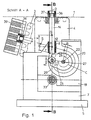
- This role 18 is with a Conductor 20 in contact, which is fixed in a plate 19 fixed to the frame 5 located.
- This interconnect 20 is preferably circular, so it is light produced. It merges into a straight area A and a straight area B at the beginning and at the end of the interconnect 20 (see FIG. 1).
- To move the Roller 18 along the interconnect 20 serves a lever 21 which is around the stationary Pivot point 22 can be pivoted through the angle C. (see Figure 1).
- To the lever 21 has a recess 23 with which it is a roller bearing 24 Grips outer ring, which sits on the bolt 17, which also carries the roller 18.
- the Recess 23 is semicircular, merging into a slot. ( see Figure 6).
- the pivoting movement of the lever 21 can take place in that the movement of the two levers 21 is synchronized via a synchronism and the synchronous shaft is driven directly via a servo motor.
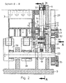
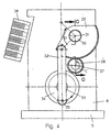
- An advantageous embodiment is shown in Figures 2 to 4.
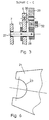
- the two levers 21 each sit on a pin 27, which is mounted in the side cheeks 6, 7 and also carries a gear wheel 28.
- a toothed segment 29 which is rotatably mounted on a pin 30 held in the side wall 6.
- a pivoting movement of the toothed segment 29 by the angle D takes place via a bracket 32 articulated outside the pivot 31, which thereby causes the lever 21 to rotate.
- the tab 32 is displaced from a main shaft 33 on which a disk 34 is fastened, on which the tab 32 is articulated eccentrically via the bolt 35.
- support elements 38 are seated on this main shaft 33, which is mounted in the frame 5 or in the side troughs 6, 7 support in one or more places. This means that high forming and punching forces, caused by supplying the molding air and lowering the upper part of the tool to generate the punching stroke, can be absorbed well.
- This design of the device makes it possible to achieve the alternating direction of the movement of the swivel table 4 and optimal support of the swivel table 4 by means of a single drive acting on the main shafts 33 in one direction of rotation - preferably via a servo drive.
- bearing eyes 36 are on the frame 5 or on the side walls 6 arranged, into which the rods 14 dip with their shoulder 37.
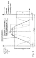
- the second half of the Swing angle C increases the distance up to a value Y at whole pivoted and just shifted over a linear region B and possibly guided swivel table 4. It is advantageous to select this value Y greater than the value X as the braking effect caused by increasing this Distance when swiveling in stack position should be greater than when starting the closed position, due to the downward weight of the Swiveling table 4.
- the second half of the Work cycle in reverse order of movements up to Closed position. That is, the distance from center of gravity S to pivot point 11 first decreases and then increases again up to the value X in Closed position. In this closed position, the drive for the main shaft 33 stops a predetermined time T in which the containers are shaped by differential pressure, cooled and punched out by a lifting movement of the upper part of the tool become.
Landscapes
- Engineering & Computer Science (AREA)
- Mechanical Engineering (AREA)
- Blow-Moulding Or Thermoforming Of Plastics Or The Like (AREA)
- Perforating, Stamping-Out Or Severing By Means Other Than Cutting (AREA)
- Moulds For Moulding Plastics Or The Like (AREA)
- Making Paper Articles (AREA)
Claims (17)
- Procédé pour entraíner une table basculante (4) portant la moitié d'un outil de formage (3) dans un dispositif de formage et de découpage de récipients moulés à partir d'une feuille thermoplastique par une différence de pression, la table basculante (3) étant mobile entre une position de fermeture pour le formage et le découpage et une position d'empilage pour éjecter le récipient, le centre de gravité de l'ensemble formé par la table (4) et la moitié de l'outil de formage (3) se situant dans les positions terminales, au-delà du point de basculement (11) autour duquel cet ensemble est basculé,
caractérisé en ce que
pendant le basculement de la table basculante (4) d'un angle de basculement (C) la distance entre le centre de gravité (S) et le point de basculement (11) diminue tout d'abord et après avoir parcouru la moitié de l'angle de basculement (C) cette distance augmente de nouveau. - Procédé selon la revendication 1,
caractérisé en ce que
la variation de la distance entre le centre de gravité (S) et le point de basculement (11) est une variation continue pendant le mouvement de la table basculante (4). - Procédé selon l'une quelconque des revendications 1 ou 2,
caractérisé en ce que
la distance minimale entre le centre de gravité (S) et le point de basculement (11) correspond au demi-angle de basculement (C). - Procédé selon l'une quelconque des revendications 1 à 3,
caractérisé en ce que
la distance entre le centre de gravité (S) et le point de basculement (11) atteint la valeur zéro. - Procédé selon l'une quelconque des revendications 1 à 4,
caractérisé en ce que
la distance (X, Y) entre le centre de gravité (S) et le point d'articulation (11) est la même en position de fermeture et en position d'empilage de la table basculante (4). - Procédé selon l'une quelconque des revendications 1 à 4,
caractérisé en ce que
la distance (X, Y) entre le centre de gravité (S) et le point de basculement (11) est différente en position de fermeture et en position d'empilage de la table basculante (4). - Procédé selon l'une quelconque des revendications 1 à 4,
caractérisé en ce que
la distance (Y) entre le centre de gravité (S) et le point de basculement (11) en position d'empilage de la table basculante (4) est plus grande que la distance (X) de la table en position de fermeture. - Procédé selon l'une quelconque des revendications 1 à 7,
caractérisé en ce que
la table basculante (4) est guidée de manière complémentaire lorsqu'elle se rapproche de sa position de fermeture et/ou de sa position d'empilage. - Procédé selon l'une quelconque des revendications 1 à 8,
caractérisé en ce que
la table basculante (4) est soutenue en plus par en dessous en position de fermeture. - Dispositif pour le formage et le découpage de récipients à partir d'une feuille thermoplastique comportant un poste de formage et un outil de formage dont une moitié est installée sur une table basculante,
caractérisé en ce que :a) de part et d'autre de la table basculante (4) est fixée une barre (14),b) les deux barres (14) glissent chacune dans une partie de guidage (8) fixe, basculante autour d'un point de basculement (11),c) chaque barre (14) porte un galet (18) à son extrémité opposée à la bande de film,d) ce galet (18) est en appui contre un chemin de guidage fixe (20),e) un levier (21) agissant sur chaque barre (14) pour guider le galet (18) le long du chemin de guidage (20). - Dispositif selon la revendication 10,
caractérisé en ce que
le chemin de guidage (20) a une forme circulaire et le point de rotation (22) du levier (21) se trouve au centre du chemin de guidage circulaire (20). - Dispositif selon l'une quelconque des revendications 10 ou 11,
caractérisé en ce que
le chemin de guidage (20) présente une zone droite (A, B) à l'une ou à ses deux extrémités. - Dispositif selon la revendication 12,
caractérisé par
un chemin de guidage fixe (26) pour guider chaque barre (14) lors du passage de la zone droite (A, B). - Dispositif selon la revendication 13,
caractérisé en ce que
le guidage des barres (14) dans la zone droite (A, B) se fait par un galet (25) porté par le même axe (17) que le galet (18) guidé par le chemin de guidage (20). - Dispositif selon l'une quelconque des revendications 10 à 14,
caractérisé en ce que
le mouvement de basculement des leviers (21) est assuré par un couplage avec un arbre principal (33), entraíné. - Dispositif selon la revendication 15,
caractérisé en ce que
l'arbre principal (33) porte un disque (34) muni de manière excentrée d'une patte (32) reliée à un segment denté (29) monté fixe, le segment denté (29) entraínant une roue dentée (28) fixée sur l'axe (27) qui porte également le levier (21). - Dispositif selon l'une quelconque des revendications 15 ou 16,
caractérisé par
des éléments de support (38) portés par l'arbre principal (33), ces éléments étant réalisés pour soutenir en un ou plusieurs endroits la table basculante (4) en position de fermeture.
Applications Claiming Priority (2)
| Application Number | Priority Date | Filing Date | Title |
|---|---|---|---|
| DE19921668 | 1999-05-11 | ||
| DE19921668A DE19921668C1 (de) | 1999-05-11 | 1999-05-11 | Verfahren zum Bewegen eines Schwenktisches in einer Vorrichtung zum Formen und Ausstanzen von Behältern aus einer thermoplastischen Kunststoffolie und Vorrichtung zur Durchführung des Verfahrens |
Publications (3)
| Publication Number | Publication Date |
|---|---|
| EP1052080A2 EP1052080A2 (fr) | 2000-11-15 |
| EP1052080A3 EP1052080A3 (fr) | 2002-01-02 |
| EP1052080B1 true EP1052080B1 (fr) | 2002-11-27 |
Family
ID=7907692
Family Applications (1)
| Application Number | Title | Priority Date | Filing Date |
|---|---|---|---|
| EP00108517A Expired - Lifetime EP1052080B1 (fr) | 1999-05-11 | 2000-04-19 | Procédé pour déplacer une table basculante dans un dispositif de formage et de découpage de récipients moulés à partir d'une feuille thermoplastique et dispositif pour sa mise en oeuvre |
Country Status (5)
| Country | Link |
|---|---|
| US (1) | US6558150B1 (fr) |
| EP (1) | EP1052080B1 (fr) |
| AT (1) | ATE228430T1 (fr) |
| DE (2) | DE19921668C1 (fr) |
| DK (1) | DK1052080T3 (fr) |
Families Citing this family (15)
| Publication number | Priority date | Publication date | Assignee | Title |
|---|---|---|---|---|
| DE10100119C1 (de) * | 2001-01-03 | 2002-06-20 | Illig Maschinenbau Adolf | Kombinierte Form-/Stanzstation zum Formen und Ausstanzen von Behältern aus einer Folienbahn aus thermoplastischem Kunststoff |
| DK1497099T3 (da) * | 2002-04-25 | 2011-07-11 | Kuhne Anlagenbau Gmbh | Termoformanlæg til fremstilling af formlegemer af plastfolie og fremgangsmåde til fremstilling af samme |
| AU2004100000A4 (en) | 2004-01-02 | 2004-02-12 | Sands Innovations Pty Ltd | Dispensing stirring implement |
| DE102005035459B4 (de) * | 2005-07-28 | 2007-09-27 | Mould & Matic Solutions Gmbh | Vorrichtung zum Stapeln von Teilen aus thermoplastischem Kunststoff |
| DE102006003851B4 (de) | 2006-01-26 | 2020-06-04 | Kiefel Gmbh | Vorrichtung zum Formen, Stanzen und Stapeln von tiefgezogenen Teilen aus thermoplastischen Kunststoffen |
| JP5560041B2 (ja) | 2007-01-31 | 2014-07-23 | サンズ イノベーションズ ピーティーワイ リミテッド | 分配用具及びその製造方法 |
| ITMI20070764A1 (it) * | 2007-04-16 | 2008-10-17 | T F T S R L | Dispositivo impilatore, particolarmente per presse per la produzione di articoli in plastica quali bicchieri e simili |
| DE102008032806A1 (de) * | 2008-07-11 | 2010-01-14 | Gabler Thermoform Gmbh & Co. Kg | Vorrichtung zum Herstellen von Hohlkörpern aus thermoplastisch verformbaren Kunststoff-Folien |
| CA2746066A1 (fr) | 2008-12-09 | 2010-06-17 | Sands Innovations Pty Ltd | Contenant de distribution |
| US20100310703A1 (en) * | 2009-06-05 | 2010-12-09 | Schlepp Brian D | Thermoformer drive and tilt system |
| US20100310696A1 (en) * | 2009-06-05 | 2010-12-09 | Schlepp Brian D | Pre-loading mechanism for a tilting platen in a thermoforming press |
| USD636890S1 (en) | 2009-09-17 | 2011-04-26 | Sands Innovations Pty. Ltd. | Dispensing utensil |
| US8511500B2 (en) | 2010-06-07 | 2013-08-20 | Sands Innovations Pty. Ltd. | Dispensing container |
| US8485360B2 (en) | 2011-03-04 | 2013-07-16 | Sands Innovations Pty, Ltd. | Fracturable container |
| EP2786856B1 (fr) | 2013-04-04 | 2016-05-18 | Magna Steyr Fuel Systems GesmbH | Dispositif et procédé de fabrication de récipients en plastique |
Family Cites Families (7)
| Publication number | Priority date | Publication date | Assignee | Title |
|---|---|---|---|---|
| DE2743058C2 (de) * | 1977-09-24 | 1979-12-20 | Adolf Illig Maschinenbau Gmbh & Co, 7100 Heilbronn | Verfahren zum Steuern der Bewegung eines über eine Kurvenscheibe angetriebenen Formtisches eines Thermoformautomaten und Thermoformautomat |
| GB2142272B (en) * | 1983-05-28 | 1986-04-23 | Illig Maschinenbau Adolf | Moulding apparatus |
| DE3346628C2 (de) * | 1983-12-23 | 1986-03-27 | Adolf Illig Maschinenbau Gmbh & Co, 7100 Heilbronn | Vorrichtung zum Formen, Stanzen und Stapeln von tiefgezogenen Teilen aus thermoplastischem Kunststoff |
| US4890524A (en) * | 1988-08-31 | 1990-01-02 | John Brown Inc. | Trim press with counterbalance |
| DE19710475A1 (de) * | 1997-03-13 | 1998-09-17 | Kuhne Anlagenbau Gmbh | Vorrichtung zur Herstellung von Hohlkörpern aus thermoplastisch verformbaren Kunststoff-Folien |
| DE19716655C2 (de) * | 1997-04-21 | 2002-11-21 | Gabler Gmbh Maschbau | Vorrichtung zum Formen, Stanzen und Stapeln von tiefgezogenen Teilen aus thermoplastischem Kunststoff |
| US6135756A (en) * | 1997-06-13 | 2000-10-24 | Arends; Albert W. | Differential pressure forming, trimming and stacking apparatus |
-
1999
- 1999-05-11 DE DE19921668A patent/DE19921668C1/de not_active Expired - Fee Related
-
2000
- 2000-04-19 EP EP00108517A patent/EP1052080B1/fr not_active Expired - Lifetime
- 2000-04-19 DK DK00108517T patent/DK1052080T3/da active
- 2000-04-19 DE DE50000807T patent/DE50000807D1/de not_active Expired - Lifetime
- 2000-04-19 AT AT00108517T patent/ATE228430T1/de active
- 2000-05-11 US US09/568,510 patent/US6558150B1/en not_active Expired - Fee Related
Also Published As
| Publication number | Publication date |
|---|---|
| DK1052080T3 (da) | 2003-03-17 |
| DE50000807D1 (de) | 2003-01-09 |
| EP1052080A3 (fr) | 2002-01-02 |
| DE19921668C1 (de) | 2001-01-04 |
| US6558150B1 (en) | 2003-05-06 |
| EP1052080A2 (fr) | 2000-11-15 |
| ATE228430T1 (de) | 2002-12-15 |
Similar Documents
| Publication | Publication Date | Title |
|---|---|---|
| DE19921668C1 (de) | Verfahren zum Bewegen eines Schwenktisches in einer Vorrichtung zum Formen und Ausstanzen von Behältern aus einer thermoplastischen Kunststoffolie und Vorrichtung zur Durchführung des Verfahrens | |
| EP2706013B1 (fr) | Machine de fermeture de coques | |
| DE3346628C2 (de) | Vorrichtung zum Formen, Stanzen und Stapeln von tiefgezogenen Teilen aus thermoplastischem Kunststoff | |
| EP1221365B1 (fr) | Poste de moulage et de poinçonnage combiné pour mouler et poinçonner des récipients à partir d' une bande en matière thermoplastique | |
| DE2100426C3 (de) | Fördereinrichtung für den kontinuierlichen Transport von vorgeformten Faltbehältern mit rechteckigem Boden durch die Füll- und Verschließstationen einer Verpackungsmaschine | |
| DE102012009108A1 (de) | Transfervorrichtung für Werkstücke | |
| CH700204A2 (de) | Trenn- und Abisoliereinrichtung für eine Kabelverarbeitungsmaschine. | |
| DE112014000406T5 (de) | Kombi-Maschine zur Blasformung, Befüllung und Versiegelung | |
| EP1497099A1 (fr) | Installation de thermoformage pour la production de corps fa onnes a partir d'un film de plastique, et procede de production de tels corps | |
| EP2143550A1 (fr) | Dispositif de fabrication de corps creux en feuilles de plastique déformables thermoplastiques | |
| DE19716655C2 (de) | Vorrichtung zum Formen, Stanzen und Stapeln von tiefgezogenen Teilen aus thermoplastischem Kunststoff | |
| EP3331792B1 (fr) | Dispositif de remplissage d'un pot de filature avec un ruban de fibres | |
| DE6921987U (de) | Spritzgussmaschine. | |
| DE2155114C2 (de) | Transportvorrichtung zum Führen einer Anzahl identischer Wagen in einem Kreislauf | |
| DE19710475A1 (de) | Vorrichtung zur Herstellung von Hohlkörpern aus thermoplastisch verformbaren Kunststoff-Folien | |
| DE4033534C2 (de) | Vorrichtung zum Formen, Stanzen und Stapeln von tiefgezogenen Teilen aus thermoplastischem Kunststoff | |
| DE69803396T2 (de) | Giessvorrichtung mit abwärts bewegtem formtunnel | |
| DE4022110C2 (de) | Vorrichtung zum Schieben mehrerer Glasgegenstände von einem Transportband auf ein anderes | |
| EP1314536B1 (fr) | Dispositif pour le formage de récipients en matière plastique à partir d'une bande, et de stockage de ces récipients dans un receptacle | |
| DE69701282T2 (de) | Vorrichtung und verfahren zur rotationsformgebung | |
| EP0703060A1 (fr) | Procédé pour décharger et déposer et/ou empiler des objets moulés emboutis et dispositif pour sa mise en oeuvre | |
| DE10218511B4 (de) | Thermoformanlage zur Herstellung von Formkörpern aus Kunststofffolie, sowie Verfahren zu deren Herstellung | |
| EP1747875A2 (fr) | Appareil pour empile des pièces en matière thermoplastique | |
| DE2543567A1 (de) | Verfahren und vorrichtung zur uebergabe von artikeln von einem zufuehrenden foerderer auf eine empfangseinrichtung | |
| EP0829441A1 (fr) | Dispositif pour éjecter des feuilles imprimés et empilés |
Legal Events
| Date | Code | Title | Description |
|---|---|---|---|
| PUAI | Public reference made under article 153(3) epc to a published international application that has entered the european phase |
Free format text: ORIGINAL CODE: 0009012 |
|
| AK | Designated contracting states |
Kind code of ref document: A2 Designated state(s): AT BE CH CY DE DK ES FI FR GB GR IE IT LI LU MC NL PT SE |
|
| AX | Request for extension of the european patent |
Free format text: AL;LT;LV;MK;RO;SI |
|
| PUAL | Search report despatched |
Free format text: ORIGINAL CODE: 0009013 |
|
| AK | Designated contracting states |
Kind code of ref document: A3 Designated state(s): AT BE CH CY DE DK ES FI FR GB GR IE IT LI LU MC NL PT SE |
|
| AX | Request for extension of the european patent |
Free format text: AL;LT;LV;MK;RO;SI |
|
| 17P | Request for examination filed |
Effective date: 20011121 |
|
| GRAG | Despatch of communication of intention to grant |
Free format text: ORIGINAL CODE: EPIDOS AGRA |
|
| GRAG | Despatch of communication of intention to grant |
Free format text: ORIGINAL CODE: EPIDOS AGRA |
|
| GRAH | Despatch of communication of intention to grant a patent |
Free format text: ORIGINAL CODE: EPIDOS IGRA |
|
| GRAH | Despatch of communication of intention to grant a patent |
Free format text: ORIGINAL CODE: EPIDOS IGRA |
|
| 17Q | First examination report despatched |
Effective date: 20020524 |
|
| AKX | Designation fees paid |
Free format text: AT BE CH CY DE DK ES FI FR GB GR IE IT LI LU MC NL PT SE |
|
| GRAA | (expected) grant |
Free format text: ORIGINAL CODE: 0009210 |
|
| AK | Designated contracting states |
Kind code of ref document: B1 Designated state(s): AT BE CH CY DE DK ES FI FR GB GR IE IT LI LU MC NL PT SE |
|
| PG25 | Lapsed in a contracting state [announced via postgrant information from national office to epo] |
Ref country code: NL Free format text: LAPSE BECAUSE OF FAILURE TO SUBMIT A TRANSLATION OF THE DESCRIPTION OR TO PAY THE FEE WITHIN THE PRESCRIBED TIME-LIMIT Effective date: 20021127 Ref country code: IE Free format text: LAPSE BECAUSE OF FAILURE TO SUBMIT A TRANSLATION OF THE DESCRIPTION OR TO PAY THE FEE WITHIN THE PRESCRIBED TIME-LIMIT Effective date: 20021127 Ref country code: GR Free format text: LAPSE BECAUSE OF FAILURE TO SUBMIT A TRANSLATION OF THE DESCRIPTION OR TO PAY THE FEE WITHIN THE PRESCRIBED TIME-LIMIT Effective date: 20021127 Ref country code: FR Free format text: LAPSE BECAUSE OF FAILURE TO SUBMIT A TRANSLATION OF THE DESCRIPTION OR TO PAY THE FEE WITHIN THE PRESCRIBED TIME-LIMIT Effective date: 20021127 Ref country code: FI Free format text: LAPSE BECAUSE OF FAILURE TO SUBMIT A TRANSLATION OF THE DESCRIPTION OR TO PAY THE FEE WITHIN THE PRESCRIBED TIME-LIMIT Effective date: 20021127 Ref country code: GB Free format text: LAPSE BECAUSE OF FAILURE TO SUBMIT A TRANSLATION OF THE DESCRIPTION OR TO PAY THE FEE WITHIN THE PRESCRIBED TIME-LIMIT Effective date: 20021127 |
|
| REF | Corresponds to: |
Ref document number: 228430 Country of ref document: AT Date of ref document: 20021215 Kind code of ref document: T |
|
| REG | Reference to a national code |
Ref country code: GB Ref legal event code: FG4D Free format text: NOT ENGLISH |
|
| REG | Reference to a national code |
Ref country code: CH Ref legal event code: EP |
|
| REG | Reference to a national code |
Ref country code: IE Ref legal event code: FG4D Free format text: GERMAN |
|
| REF | Corresponds to: |
Ref document number: 50000807 Country of ref document: DE Date of ref document: 20030109 |
|
| PG25 | Lapsed in a contracting state [announced via postgrant information from national office to epo] |
Ref country code: SE Free format text: LAPSE BECAUSE OF FAILURE TO SUBMIT A TRANSLATION OF THE DESCRIPTION OR TO PAY THE FEE WITHIN THE PRESCRIBED TIME-LIMIT Effective date: 20030227 Ref country code: PT Free format text: LAPSE BECAUSE OF FAILURE TO SUBMIT A TRANSLATION OF THE DESCRIPTION OR TO PAY THE FEE WITHIN THE PRESCRIBED TIME-LIMIT Effective date: 20030227 |
|
| REG | Reference to a national code |
Ref country code: DK Ref legal event code: T3 |
|
| PG25 | Lapsed in a contracting state [announced via postgrant information from national office to epo] |
Ref country code: LU Free format text: LAPSE BECAUSE OF NON-PAYMENT OF DUE FEES Effective date: 20030419 Ref country code: CY Free format text: LAPSE BECAUSE OF FAILURE TO SUBMIT A TRANSLATION OF THE DESCRIPTION OR TO PAY THE FEE WITHIN THE PRESCRIBED TIME-LIMIT Effective date: 20030419 |
|
| PG25 | Lapsed in a contracting state [announced via postgrant information from national office to epo] |
Ref country code: MC Free format text: LAPSE BECAUSE OF NON-PAYMENT OF DUE FEES Effective date: 20030430 Ref country code: BE Free format text: LAPSE BECAUSE OF NON-PAYMENT OF DUE FEES Effective date: 20030430 |
|
| NLV1 | Nl: lapsed or annulled due to failure to fulfill the requirements of art. 29p and 29m of the patents act | ||
| PG25 | Lapsed in a contracting state [announced via postgrant information from national office to epo] |
Ref country code: ES Free format text: LAPSE BECAUSE OF FAILURE TO SUBMIT A TRANSLATION OF THE DESCRIPTION OR TO PAY THE FEE WITHIN THE PRESCRIBED TIME-LIMIT Effective date: 20030529 |
|
| REG | Reference to a national code |
Ref country code: IE Ref legal event code: FD4D Ref document number: 1052080E Country of ref document: IE |
|
| GBT | Gb: translation of ep patent filed (gb section 77(6)(a)/1977) | ||
| EN | Fr: translation not filed | ||
| PLBE | No opposition filed within time limit |
Free format text: ORIGINAL CODE: 0009261 |
|
| STAA | Information on the status of an ep patent application or granted ep patent |
Free format text: STATUS: NO OPPOSITION FILED WITHIN TIME LIMIT |
|
| BERE | Be: lapsed |
Owner name: *ILLIG ADOLF MASCHINENBAU G.M.B.H. & CO. Effective date: 20030430 |
|
| 26N | No opposition filed |
Effective date: 20030828 |
|
| PG25 | Lapsed in a contracting state [announced via postgrant information from national office to epo] |
Ref country code: CH Free format text: LAPSE BECAUSE OF NON-PAYMENT OF DUE FEES Effective date: 20040430 Ref country code: LI Free format text: LAPSE BECAUSE OF NON-PAYMENT OF DUE FEES Effective date: 20040430 |
|
| REG | Reference to a national code |
Ref country code: CH Ref legal event code: PL |
|
| PGFP | Annual fee paid to national office [announced via postgrant information from national office to epo] |
Ref country code: DE Payment date: 20110426 Year of fee payment: 12 |
|
| PGFP | Annual fee paid to national office [announced via postgrant information from national office to epo] |
Ref country code: GB Payment date: 20110419 Year of fee payment: 12 Ref country code: DK Payment date: 20110426 Year of fee payment: 12 Ref country code: AT Payment date: 20110418 Year of fee payment: 12 |
|
| PGFP | Annual fee paid to national office [announced via postgrant information from national office to epo] |
Ref country code: IT Payment date: 20110426 Year of fee payment: 12 |
|
| REG | Reference to a national code |
Ref country code: DK Ref legal event code: EBP |
|
| REG | Reference to a national code |
Ref country code: AT Ref legal event code: MM01 Ref document number: 228430 Country of ref document: AT Kind code of ref document: T Effective date: 20120419 |
|
| GBPC | Gb: european patent ceased through non-payment of renewal fee |
Effective date: 20120419 |
|
| PG25 | Lapsed in a contracting state [announced via postgrant information from national office to epo] |
Ref country code: AT Free format text: LAPSE BECAUSE OF NON-PAYMENT OF DUE FEES Effective date: 20120419 Ref country code: GB Free format text: LAPSE BECAUSE OF FAILURE TO SUBMIT A TRANSLATION OF THE DESCRIPTION OR TO PAY THE FEE WITHIN THE PRESCRIBED TIME-LIMIT Effective date: 20120419 |
|
| REG | Reference to a national code |
Ref country code: DE Ref legal event code: R119 Ref document number: 50000807 Country of ref document: DE Effective date: 20121101 |
|
| PG25 | Lapsed in a contracting state [announced via postgrant information from national office to epo] |
Ref country code: IT Free format text: LAPSE BECAUSE OF NON-PAYMENT OF DUE FEES Effective date: 20120419 |
|
| PG25 | Lapsed in a contracting state [announced via postgrant information from national office to epo] |
Ref country code: DK Free format text: LAPSE BECAUSE OF NON-PAYMENT OF DUE FEES Effective date: 20120430 |
|
| PG25 | Lapsed in a contracting state [announced via postgrant information from national office to epo] |
Ref country code: DE Free format text: LAPSE BECAUSE OF NON-PAYMENT OF DUE FEES Effective date: 20121101 |