EP1052147A2 - Lenkstockschalter - Google Patents
Lenkstockschalter Download PDFInfo
- Publication number
- EP1052147A2 EP1052147A2 EP00109749A EP00109749A EP1052147A2 EP 1052147 A2 EP1052147 A2 EP 1052147A2 EP 00109749 A EP00109749 A EP 00109749A EP 00109749 A EP00109749 A EP 00109749A EP 1052147 A2 EP1052147 A2 EP 1052147A2
- Authority
- EP
- European Patent Office
- Prior art keywords
- contact ring
- electrical contacts
- lever base
- moveable
- electrical
- Prior art date
- Legal status (The legal status is an assumption and is not a legal conclusion. Google has not performed a legal analysis and makes no representation as to the accuracy of the status listed.)
- Withdrawn
Links
- 238000004891 communication Methods 0.000 claims description 13
- 238000000034 method Methods 0.000 claims description 8
- 238000002788 crimping Methods 0.000 claims description 2
- 238000007747 plating Methods 0.000 claims description 2
- 230000006835 compression Effects 0.000 claims 1
- 238000007906 compression Methods 0.000 claims 1
- 238000009434 installation Methods 0.000 claims 1
- 238000013461 design Methods 0.000 abstract description 17
- 230000008901 benefit Effects 0.000 description 5
- 238000010276 construction Methods 0.000 description 3
- 239000000463 material Substances 0.000 description 3
- 239000004033 plastic Substances 0.000 description 3
- 230000013011 mating Effects 0.000 description 2
- 230000007246 mechanism Effects 0.000 description 2
- 230000008569 process Effects 0.000 description 2
- 239000004677 Nylon Substances 0.000 description 1
- 230000009471 action Effects 0.000 description 1
- 230000000712 assembly Effects 0.000 description 1
- 238000000429 assembly Methods 0.000 description 1
- 238000011161 development Methods 0.000 description 1
- 239000000428 dust Substances 0.000 description 1
- 239000011796 hollow space material Substances 0.000 description 1
- 238000004519 manufacturing process Methods 0.000 description 1
- 229920001778 nylon Polymers 0.000 description 1
- 238000011160 research Methods 0.000 description 1
- 238000005476 soldering Methods 0.000 description 1
- 238000003860 storage Methods 0.000 description 1
- 238000012360 testing method Methods 0.000 description 1
Images

Classifications
-
- B—PERFORMING OPERATIONS; TRANSPORTING
- B60—VEHICLES IN GENERAL
- B60Q—ARRANGEMENT OF SIGNALLING OR LIGHTING DEVICES, THE MOUNTING OR SUPPORTING THEREOF OR CIRCUITS THEREFOR, FOR VEHICLES IN GENERAL
- B60Q1/00—Arrangement of optical signalling or lighting devices, the mounting or supporting thereof or circuits therefor
- B60Q1/02—Arrangement of optical signalling or lighting devices, the mounting or supporting thereof or circuits therefor the devices being primarily intended to illuminate the way ahead or to illuminate other areas of way or environments
- B60Q1/04—Arrangement of optical signalling or lighting devices, the mounting or supporting thereof or circuits therefor the devices being primarily intended to illuminate the way ahead or to illuminate other areas of way or environments the devices being headlights
- B60Q1/14—Arrangement of optical signalling or lighting devices, the mounting or supporting thereof or circuits therefor the devices being primarily intended to illuminate the way ahead or to illuminate other areas of way or environments the devices being headlights having dimming means
- B60Q1/1446—Arrangement of optical signalling or lighting devices, the mounting or supporting thereof or circuits therefor the devices being primarily intended to illuminate the way ahead or to illuminate other areas of way or environments the devices being headlights having dimming means controlled by mechanically actuated switches
- B60Q1/1453—Hand actuated switches
- B60Q1/1461—Multifunction switches for dimming headlights and controlling additional devices, e.g. for controlling direction indicating lights
- B60Q1/1469—Multifunction switches for dimming headlights and controlling additional devices, e.g. for controlling direction indicating lights controlled by or attached to a single lever, e.g. steering column stalk switches
- B60Q1/1476—Multifunction switches for dimming headlights and controlling additional devices, e.g. for controlling direction indicating lights controlled by or attached to a single lever, e.g. steering column stalk switches comprising switch controlling means located near the free end of the lever, e.g. press buttons, rotatable rings
Definitions
- the present invention relates in general to a steering column stalk switch, and more specifically to a steering column mounted stalk or lever switch controlling various vehicle operating circuits and/or devices.
- Steering column lever switches or stalk switches are well known in the vehicle industry. These devices are typically used to control turn signals, windshield wipers, windshield washers, cruise control, or any variety or combination of devices.
- the lever switch includes a rotatable operating knob which can be turned between an off position and a variety of actuating positions, for example, for various speeds of a windshield wiper, or for intermittent operation.
- the handle may also include an outer sleeve that rotates for actuating the windshield washer system.
- U.S. Patent No. 4,387,279 describes a multi-function lever switch for a steering column.
- lever switches may be found in the following patents: U.S. Patent No. 3,881,076; 5,049,706; 4,427,850; 4,408,104; 5,661,276; and 5,453,588.
- the prior art single lever switches use a so-called radial type contact system design that employs either a horizontally located printed circuit board (PCB) or an insert molded electrical contact part.
- PCB printed circuit board
- a switch would consist of two rotating contact rings with stationary blade contacts.
- the axial type contact design offers a more robust geometry with less position deviations. It requires less parts compared with the conventional radial type contact design and requires less assembly operations.
- a single lever switch in accordance with the present invention employs two independent contact systems located axially to implement, for example, a front and rear wipe/wash system.
- a lever base includes a plurality of axially disposed electrical contacts at one end and receives a first moveable contact ring thereon.
- the radially moveable contact ring includes a plurality of electrical contacts therein which are in electrical communication with the plurality of axially disposed electrical contacts on the lever base.
- a stationary contact ring is then positioned at the end of the lever base so as to interpose the first moveable contact ring between the stationary contact ring and the lever base.
- the stationary contact ring includes a plurality of axially disposed electrical contacts with at least one of the axially disposed electrical contacts being in communication with at least one of the electrical contacts on the first moveable contact ring.
- the stationary contact ring includes a projecting portion which receives a second moveable contact ring positioned thereover.
- the second radially moveable contact ring includes a plurality of electrical contacts therein in electrical communication with the plurality of axially disposed electrical contacts upon the stationary contact ring.
- a cover is positioned on a distal end of the projecting portion of the stationary contact ring.
- the cover includes a resiliently actuatable button with an electrical contact.
- the button with the electrical contact communicates with at least one of the plurality of axially disposed electrical contacts in the stationary contact ring.
- the present invention includes a first and second cam ring positioned inside the first and second moveable contact rings for providing selected engagements of the plurality of electrical contacts for achievement of desired purposes for electrical communication with a variety of electrical circuits
- An object of the present invention is to provide a multi-function single lever switch for a vehicle.
- Another object of the present invention is to provide a multi-function single lever switch using two independent contact systems employing an axial type contact design.
- Another object of the present invention is to provide a single lever switch that employs less parts compared with a conventional lever design.
- Another object of the present invention is to provide a single lever switch that requires less assembly operations.
- Still another object of the present invention is to provide a multi-function single lever switch that employs two rotating contact rings with stationary blade contacts.
- Each contact ring includes a set of cams located inside for selective engagement of the electrical contacts.
- Still a further object of the present invention is to provide a multi-function single lever switch which is simple in design, rugged in construction, and economical to manufacture.
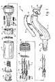
- Lever switch 10 is a multi-function lever switch constructed for connection in a vehicle steering column (not shown) and is operative to control the operation of various operating devices or circuits found in vehicles, such as a vehicle windshield wiper and washer control for the front window and/or the rear window, turn signals, vehicle headlights, vehicle headlight switching between low and high beam, or any other desired function typically found in a vehicle.
- the lever switch 10 includes a lever base 12 which is preferably generally tubular in construction and has a connecting arm 62 with a switch finger 64 for mounting in a steering column (not shown).
- the other end 18 of lever base 12 has also a preferable tubular construction with a slightly reduced diameter from a main portion of the lever base 12.
- Lever base 12 further preferably terminates with a plurality of engaging members 60 designed to snap and lock within a mating receptacle.
- engaging members 60 may be arranged in a spaced hexagonal arrangement with each side of the hexagon being separated by an axially extending slot to merely slide and snap lock into a mating receptacle.
- a plurality of axially disposed electrical contacts 16 are positioned circumferentially on the reduced end 18 of lever base 12.
- lever base 12 includes a compartment 54 which basically is a hollow space in the interior of lever base 12 and is releasably sealed with a lever base closeout 52. Compartment 54 provides storage for the wires 15 employed with the lever switch 10 of the present invention.
- the first moveable contact ring 20 with the preferable integral cam ring 50 inside has an internal bore that corresponds to the size of the reduced end 18 of lever base 12.
- the outer surface of ring 20 is preferably dimpled as shown in FIG. 1.
- a plurality of electrical contacts 22 are provided in an interior surface of moveable contact ring 20 at a distance and spacing to allow electrical communication with axially disposed electrical contacts 16 and axially disposed electrical contacts 26. Electrical contacts 26 are spaced circumferentially about a projecting portion 28 of stationary contact ring 24. As shown in FIG.
- electrical contacts 26 are stationary blade contacts that simply slide through corresponding apertures in stationary contact ring 24 in a sleeve or press fit arrangement that allows a portion of the blade contact to be disposed about the periphery of projecting portion 28. At least one of the electrical contacts 26 extends inwardly towards the first moveable contact ring to electrically communicate with the first moveable contact ring 20.
- Stationary contact ring 24 is constructed to be received on end 18 of lever base 12 with the first moveable contact ring 20 interposed therebetween.
- Engaging members 60 snap lock the stationary ring 24 onto end 18 in a manner that allows contact ring 20 to radially move on end 18.
- Plungers 48 are optionally provided to facilitate attachment of an external cam ring when used and to interconnect the pieces.
- Projection portion 28 of stationary contact ring 24 terminates in at least one locking tab 68 to snap fit within button 36, and still allow button 36 to slidably move thereon.
- the plurality of electrical contacts 22 in the interior of contact ring 20 are preferably plated on a die cast contact surface about a circumferential portion thereof for a desired electrical communication with one or more of the electrical contacts 16, 26.
- Vertically arranging contacts 16, 26 or contacts 22, 32 allow a variety of desired operator controllable settings or positions.
- a second moveable contact ring 30 with preferably a cam inside and a plurality of electrical contacts 32 on an inner surface thereof similar to contacts 22 has an internal diameter corresponding to the projecting portion 28 of stationary contact ring 24.
- a plurality of springs 46 and plungers 48 resiliently bias contact ring 30 away from stationary contact ring 24.
- the cam ring 44 may be external to contact ring 30 rather than situated on the inside.
- an inward edge of contact ring 30 contains a plurality of teeth 70 for a radial ratcheting action that provides precise settings and positional control.
- a stopping protrusion 72 limits the rotational movement of contact ring 30.
- Contact ring 30 has an outer diameter that allows the contact ring 30 to fit within the inner diameter of a cover 34.
- Contact ring 30 preferably includes a groove 74 constructed to engage and mesh with a raised rib (not shown) inside cover 34. As cover 34 is rotated, this causes rotation of second moveable contact ring 30 therewith.
- Cover 34 is preferably cylindrical and includes an opening with an edge to accommodate button 36 therein at its distal end.
- Button 36 is resiliently biased with spring 76 against projecting portion 28 of stationary contact ring 24.
- Projecting portion 28 preferably has a stepped down diameter to provide for a supporting surface for spring 76.
- Spring 76 has a diameter corresponding to one of the reduced diameters of the projecting portion.
- An electrical contact 40 which may be incorporated within button 36 or be an external assembly as shown in FIG. 1 provides electrical communication with at least one of the plurality of electrical contacts on stationary ring 24. Spring 76 biases the electrical contact 40 away from an electrical contact on the second moveable contact ring 30.
- Lever switch 10 is a full function single lever switch based on two independent contact systems located axially perpendicularly to the lever centerline (to preferably implement front and rear wipe/wash functions).
- the lever switch preferably consists of two rotating contact rings and stationary blade contacts.
- Each of the contact rings preferably has a set of cams located inside in a set order to have engagements with the corresponding stationary contacts to provide a set of binary codes or electrical signals for the electronic module or vehicle processor.
- the single lever switch in accordance with the present invention employs an axial type contact system design that is more robust and not sensitive to the axial part geometry, and/or position deviations encountered with the prior art radial type contact system design.
- the lever switch of the present invention provides several advantages including but not limited to a contact force, deflection and stress relaxation that are more stable.
- the present invention requires approximately 20% less parts compared with the conventional lever design. It also provides an advantage of approximately 30% less assembly operations.
- the design of the lever switch in accordance with the present invention allows the use of the assembled wires with preferably crimped terminals. This can be a bottle neck for other lever switch assemblies.
- the design of the present invention provides for an assembly process that may be automated.
- Still another advantage of the present invention is that it allows the use of common parts such as electrical blade contacts as a result of the axial type contact system.
- the simple assembly of the lever switch according to the present invention allows the checking or testing of parts for fit, form, function, at any time during the assembly process.
- the design of the lever switch in accordance with the present invention further allows a decrease in the outside lever diameter.
- the lever switch provides an axial loaded contact system.
- the common electrical blade contacts are employed for front and/or rear wiper/wash functions.
- the lever switch allows the use of a common ground contact between the front and rear contact systems.
- an assembled wire harness can be located through openings inside the lever core or base.
- the lever switch allows for a slide mechanism for the wash contact function.
- the first and/or second moveable contact rings may be a die cast contact ring with an integral cam ring with plating including plated tabs connecting portions of an electrical band.
- Each contact ring includes a set of cams located inside in a set order to have engagements with corresponding stationary electrical contacts to provide a set of electrical signals or binary codes for electronic modules or vehicle processors.
- the rotating contact cam rings are preferably included as part of the front and/or rear plastic contact rings.
- the design of the lever switch in accordance with the present invention allows for self locking mechanisms between the parts. Common springs and plungers are employed from front/rear detent structures.
- the lever switch is preferably constructed from a plastic material except for the electrical contacts and springs. The plastic material such as a reinforced nylon material insulates the contacts from each other. A raised portion on an electrical stationary blade contact provides an electrical connection with the electrical contact in the first and/or second moveable contact rings.
- Still another advantage of the present invention is that it requires no additional parts for wires strain relief.
- the more secure design of the instant invention inhibits dust from entering inside the lever as easily as the prior art.
- FIG. 2 shows a portion of the assembled lever switch and the secure design.
Landscapes
- Engineering & Computer Science (AREA)
- Mechanical Engineering (AREA)
- Switches With Compound Operations (AREA)
Applications Claiming Priority (2)
| Application Number | Priority Date | Filing Date | Title |
|---|---|---|---|
| US09/309,674 US6025564A (en) | 1999-05-11 | 1999-05-11 | Single stalk steering column switch |
| US309674 | 2002-12-04 |
Publications (1)
| Publication Number | Publication Date |
|---|---|
| EP1052147A2 true EP1052147A2 (de) | 2000-11-15 |
Family
ID=23199187
Family Applications (1)
| Application Number | Title | Priority Date | Filing Date |
|---|---|---|---|
| EP00109749A Withdrawn EP1052147A2 (de) | 1999-05-11 | 2000-05-08 | Lenkstockschalter |
Country Status (2)
| Country | Link |
|---|---|
| US (1) | US6025564A (de) |
| EP (1) | EP1052147A2 (de) |
Cited By (1)
| Publication number | Priority date | Publication date | Assignee | Title |
|---|---|---|---|---|
| EP1783795A1 (de) * | 2005-11-05 | 2007-05-09 | Delphi Technologies Inc. | Elektrische Schalteinrichtung |
Families Citing this family (9)
| Publication number | Priority date | Publication date | Assignee | Title |
|---|---|---|---|---|
| DE19631208A1 (de) * | 1996-08-02 | 1998-02-05 | Eaton Controls Gmbh | Lenkstockschalter für ein Kraftfahrzeug |
| US6274835B1 (en) * | 1999-11-15 | 2001-08-14 | Siemens Energy & Automation | Selector switch operator |
| US6566616B1 (en) | 2001-10-31 | 2003-05-20 | Delphi Technologies, Inc. | Multiple switch module |
| KR100604957B1 (ko) * | 2004-10-18 | 2006-07-28 | 한국전자통신연구원 | 광 편향기 |
| JP4490299B2 (ja) * | 2005-02-01 | 2010-06-23 | 株式会社東海理化電機製作所 | レバースイッチ装置 |
| US7518071B2 (en) * | 2007-07-26 | 2009-04-14 | Grote Industries, Inc. | Turn signal self cancellation system |
| JP6274793B2 (ja) * | 2013-09-12 | 2018-02-07 | 矢崎総業株式会社 | コンビネーションスイッチ |
| EP3035357B1 (de) * | 2014-12-19 | 2017-07-19 | Siemens Aktiengesellschaft | Modulares elektromechanisches Schaltelement |
| JP6218188B2 (ja) * | 2015-02-25 | 2017-10-25 | 株式会社東海理化電機製作所 | スイッチ装置 |
Citations (7)
| Publication number | Priority date | Publication date | Assignee | Title |
|---|---|---|---|---|
| US3881076A (en) | 1974-04-12 | 1975-04-29 | Ford Motor Co | Steering column vehicle switch assembly having rotary and lineal movement |
| US4387279A (en) | 1981-10-19 | 1983-06-07 | Methode Electronics, Inc. | Column mounted switch for vehicles and the like |
| US4408104A (en) | 1981-03-27 | 1983-10-04 | Kabushiki Kaisha Tokai Rika Denki Seisakusho | Lever switch arrangement for motor vehicle |
| US4427850A (en) | 1981-05-29 | 1984-01-24 | Fiat Auto S.P.A. | Monostable switch device for controlling the rear window washer/wiper of an automobile |
| US5049706A (en) | 1990-05-25 | 1991-09-17 | Rocher Daniel J Du | Multifunction steering column switch |
| US5453588A (en) | 1992-11-06 | 1995-09-26 | Itt Corporation | Steering column stalk switch apparatus |
| US5661276A (en) | 1995-04-11 | 1997-08-26 | Niles Parts Co., Ltd. | Automobile lever switch having a plate spring with movable contact points and multiple holding fingers |
Family Cites Families (18)
| Publication number | Priority date | Publication date | Assignee | Title |
|---|---|---|---|---|
| US3511943A (en) * | 1968-06-27 | 1970-05-12 | Mccord Corp | Control switch for a vehicle windshield washer and wiper system contained in a turn signal actuating lever |
| GB1428657A (en) * | 1972-05-06 | 1976-03-17 | Lucas Electrical Co Ltd | Electrical switches |
| US3940579A (en) * | 1973-07-16 | 1976-02-24 | Swf-Spezialfabrik Fur Autozubehor Gustav Rau Gmbh | Plural switch construction having rotary and linear switch contact assemblies operated by independent operators |
| DE2810790C3 (de) * | 1978-03-13 | 1980-10-09 | Adam Opel Ag, 6090 Ruesselsheim | Lenkstockschalter für Kraftfahrzeuge |
| DE2828592C2 (de) * | 1978-06-29 | 1980-01-03 | Fa. Leopold Kostal, 5880 Luedenscheid | Lenkstockschalter für Kraftfahrzeuge |
| DE3121659C2 (de) * | 1981-05-30 | 1985-04-18 | Leopold Kostal GmbH & Co KG, 5880 Lüdenscheid | Lenkstockschalter mit einem Warnblinkschalter |
| DE3537299A1 (de) * | 1985-10-19 | 1987-04-23 | Swf Auto Electric Gmbh | Elektrischer schalter, insbesondere lenkstockschalter fuer kraftfahrzeuge |
| DE3626242A1 (de) * | 1986-08-02 | 1988-02-04 | Swf Auto Electric Gmbh | Schalter, insbesondere lenkstockschalter fuer kraftfahrzeuge |
| DE3717251C2 (de) * | 1987-05-22 | 2001-10-04 | Teves Gmbh Alfred | Elektrischer Schalter, insbesondere Lenkstockschalter für Kraftfahrzeuge |
| FR2636148B1 (fr) * | 1988-09-08 | 1992-02-14 | Jaeger | Manette de commande en particulier pour vehicule automobile |
| DE4016772C2 (de) * | 1990-05-25 | 1999-08-19 | Teves Gmbh Alfred | Elektrischer Schalter zum Betreiben einer Scheibenwischanlage und einer Scheibenwaschanlage eines Kraftfahrzeugs |
| DE4137654A1 (de) * | 1991-11-15 | 1993-05-19 | Swf Auto Electric Gmbh | Elektrisches geraet, insbesondere lenkstockschalter fuer kraftfahrzeuge |
| DE4305827C2 (de) * | 1993-02-25 | 2002-02-07 | Eaton Controls Gmbh | Lenkstockschalter für Kraftfahrzeuge |
| US5691519A (en) * | 1993-03-25 | 1997-11-25 | Eaton Corporation | Electric switch, for use on automotive steering column switch |
| FR2718095B1 (fr) * | 1994-03-31 | 1996-05-15 | Valeo Electronique | Support de commutateurs pour colonne de direction d'un véhicule automobile. |
| JP3680382B2 (ja) * | 1995-11-09 | 2005-08-10 | 松下電器産業株式会社 | スイッチレバー |
| JPH10172389A (ja) * | 1996-12-11 | 1998-06-26 | Niles Parts Co Ltd | レバースイッチ装置 |
| US5760355A (en) * | 1997-03-11 | 1998-06-02 | Itt Manufacturing Enterprises, Inc. | Electric switch for operating a windshield wiper and washer apparatus of a motor vehicle |
-
1999
- 1999-05-11 US US09/309,674 patent/US6025564A/en not_active Expired - Fee Related
-
2000
- 2000-05-08 EP EP00109749A patent/EP1052147A2/de not_active Withdrawn
Patent Citations (7)
| Publication number | Priority date | Publication date | Assignee | Title |
|---|---|---|---|---|
| US3881076A (en) | 1974-04-12 | 1975-04-29 | Ford Motor Co | Steering column vehicle switch assembly having rotary and lineal movement |
| US4408104A (en) | 1981-03-27 | 1983-10-04 | Kabushiki Kaisha Tokai Rika Denki Seisakusho | Lever switch arrangement for motor vehicle |
| US4427850A (en) | 1981-05-29 | 1984-01-24 | Fiat Auto S.P.A. | Monostable switch device for controlling the rear window washer/wiper of an automobile |
| US4387279A (en) | 1981-10-19 | 1983-06-07 | Methode Electronics, Inc. | Column mounted switch for vehicles and the like |
| US5049706A (en) | 1990-05-25 | 1991-09-17 | Rocher Daniel J Du | Multifunction steering column switch |
| US5453588A (en) | 1992-11-06 | 1995-09-26 | Itt Corporation | Steering column stalk switch apparatus |
| US5661276A (en) | 1995-04-11 | 1997-08-26 | Niles Parts Co., Ltd. | Automobile lever switch having a plate spring with movable contact points and multiple holding fingers |
Cited By (1)
| Publication number | Priority date | Publication date | Assignee | Title |
|---|---|---|---|---|
| EP1783795A1 (de) * | 2005-11-05 | 2007-05-09 | Delphi Technologies Inc. | Elektrische Schalteinrichtung |
Also Published As
| Publication number | Publication date |
|---|---|
| US6025564A (en) | 2000-02-15 |
Similar Documents
| Publication | Publication Date | Title |
|---|---|---|
| US5701660A (en) | Method for making a multi-function switch stalk assembly | |
| US6020563A (en) | Multi-function stalk switch | |
| US5491311A (en) | Multifunction switch | |
| US6025564A (en) | Single stalk steering column switch | |
| EP3061652B1 (de) | Schaltvorrichtung | |
| US6384351B1 (en) | Switch apparatus for actuating a plurality of electrical circuits | |
| US8772662B2 (en) | Rotary switch | |
| EP1207076A2 (de) | Mehrfunktionslenksäulenhebelschalter | |
| US5905237A (en) | Vehicular knob switch apparatus | |
| EP3061668B1 (de) | Schaltvorrichtung | |
| US4996401A (en) | Switch | |
| US6127638A (en) | Combination switch | |
| EP0496123B1 (de) | Schalteraufbau | |
| US6365852B1 (en) | Steering column switch for motor vehicles | |
| US5665948A (en) | Automobile knob switch | |
| KR19990062527A (ko) | 회전 커넥터 장착 컬럼스위치 | |
| US6403899B1 (en) | Vehicle fog lamp interlock switch apparatus | |
| US5861593A (en) | Modular switch stalk assemblable in different orientations to provide different rotation features | |
| JP3680435B2 (ja) | スイッチレバーおよびその製造方法 | |
| EP1291241B1 (de) | Komplexer Hebelschalter für Fahrzeuge | |
| KR100410881B1 (ko) | 자동차용 클럭 스프링 | |
| KR100342837B1 (ko) | 자동차용 자동 등화스위치 | |
| KR100658044B1 (ko) | 포그램프 스위치 겸용 라이트 스위치 장치 | |
| KR100862003B1 (ko) | 레버 스위치 장치 | |
| US3413427A (en) | Direction signal switch incorporating windshield wiper and washer operating mechanism |
Legal Events
| Date | Code | Title | Description |
|---|---|---|---|
| PUAI | Public reference made under article 153(3) epc to a published international application that has entered the european phase |
Free format text: ORIGINAL CODE: 0009012 |
|
| AK | Designated contracting states |
Kind code of ref document: A2 Designated state(s): AT BE CH CY DE DK ES FI FR GB GR IE IT LI LU MC NL PT SE |
|
| AX | Request for extension of the european patent |
Free format text: AL;LT;LV;MK;RO;SI |
|
| RAP1 | Party data changed (applicant data changed or rights of an application transferred) |
Owner name: DELPHI TECHNOLOGIES, INC. |
|
| STAA | Information on the status of an ep patent application or granted ep patent |
Free format text: STATUS: THE APPLICATION IS DEEMED TO BE WITHDRAWN |
|
| 18D | Application deemed to be withdrawn |
Effective date: 20051201 |