EP1052148A2 - Réseau de bord de véhicule - Google Patents
Réseau de bord de véhicule Download PDFInfo
- Publication number
- EP1052148A2 EP1052148A2 EP20000108705 EP00108705A EP1052148A2 EP 1052148 A2 EP1052148 A2 EP 1052148A2 EP 20000108705 EP20000108705 EP 20000108705 EP 00108705 A EP00108705 A EP 00108705A EP 1052148 A2 EP1052148 A2 EP 1052148A2
- Authority
- EP
- European Patent Office
- Prior art keywords
- electrical system
- circuit
- consumers
- voltage
- power supply
- Prior art date
- Legal status (The legal status is an assumption and is not a legal conclusion. Google has not performed a legal analysis and makes no representation as to the accuracy of the status listed.)
- Withdrawn
Links
Images
Classifications
-
- H—ELECTRICITY
- H02—GENERATION; CONVERSION OR DISTRIBUTION OF ELECTRIC POWER
- H02J—ELECTRIC POWER NETWORKS; CIRCUIT ARRANGEMENTS OR SYSTEMS FOR SUPPLYING OR DISTRIBUTING ELECTRIC POWER; SYSTEMS FOR STORING ELECTRIC ENERGY
- H02J1/00—Circuit arrangements for DC mains or DC distribution networks
- H02J1/08—Three-wire DC power distribution systems; Systems having more than three wires
-
- H—ELECTRICITY
- H02—GENERATION; CONVERSION OR DISTRIBUTION OF ELECTRIC POWER
- H02J—ELECTRIC POWER NETWORKS; CIRCUIT ARRANGEMENTS OR SYSTEMS FOR SUPPLYING OR DISTRIBUTING ELECTRIC POWER; SYSTEMS FOR STORING ELECTRIC ENERGY
- H02J9/00—Circuit arrangements for emergency or stand-by power supply, e.g. for emergency lighting
- H02J9/04—Circuit arrangements for emergency or stand-by power supply, e.g. for emergency lighting in which the distribution system is disconnected from the normal source and connected to a standby source
- H02J9/06—Circuit arrangements for emergency or stand-by power supply, e.g. for emergency lighting in which the distribution system is disconnected from the normal source and connected to a standby source with automatic change-over, e.g. UPS systems
- H02J9/061—Circuit arrangements for emergency or stand-by power supply, e.g. for emergency lighting in which the distribution system is disconnected from the normal source and connected to a standby source with automatic change-over, e.g. UPS systems for DC powered loads
-
- B—PERFORMING OPERATIONS; TRANSPORTING
- B60—VEHICLES IN GENERAL
- B60R—VEHICLES, VEHICLE FITTINGS, OR VEHICLE PARTS, NOT OTHERWISE PROVIDED FOR
- B60R16/00—Electric or fluid circuits specially adapted for vehicles and not otherwise provided for; Arrangement of elements of electric or fluid circuits specially adapted for vehicles and not otherwise provided for
- B60R16/02—Electric or fluid circuits specially adapted for vehicles and not otherwise provided for; Arrangement of elements of electric or fluid circuits specially adapted for vehicles and not otherwise provided for electric constitutive elements
- B60R16/03—Electric or fluid circuits specially adapted for vehicles and not otherwise provided for; Arrangement of elements of electric or fluid circuits specially adapted for vehicles and not otherwise provided for electric constitutive elements for supply of electrical power to vehicle subsystems or for
-
- H—ELECTRICITY
- H02—GENERATION; CONVERSION OR DISTRIBUTION OF ELECTRIC POWER
- H02J—ELECTRIC POWER NETWORKS; CIRCUIT ARRANGEMENTS OR SYSTEMS FOR SUPPLYING OR DISTRIBUTING ELECTRIC POWER; SYSTEMS FOR STORING ELECTRIC ENERGY
- H02J2105/00—Networks for supplying or distributing electric power characterised by their spatial reach or by the load
- H02J2105/30—Networks for supplying or distributing electric power characterised by their spatial reach or by the load the load networks being external to vehicles, i.e. exchanging power with vehicles
- H02J2105/33—Networks for supplying or distributing electric power characterised by their spatial reach or by the load the load networks being external to vehicles, i.e. exchanging power with vehicles exchanging power with road vehicles
Definitions
- the invention relates to an electrical system for supply electrical operated consumer in motor vehicles according to the preamble of claim 1.
- a known electrical system of this type (DE 196 51 612 A1) comprises a common power supply connection for the whole Vehicle electrical system, on which preferably an electrical system control unit is connected, which in turn is connected to it connected consumers supplied.
- the vehicle electrical system control unit may include additional voltage transformers that match it supplied general power supply voltage in different Convert tensions according to the needs of each to be supplied to consumers.
- To power the various electronic or electrical components There are several to ensure safe and reliable Power supply sources, which may also be different May have voltages, one of which is provided with the voltage supply connection for the vehicle electrical system control unit is connected.
- Both electrical system circuits can share a common one Power can be supplied directly to the generator High load consumers and the starter area works and one own battery, in the special case of a 42 V electrical system a 36 V battery is assigned while the 14 V consumer via a direct voltage converter, namely a so-called DC / DC converter are connected to the generator and preferably have their own 12 V backup battery.
- the invention is therefore based on the object Multi-voltage electrical system in motor vehicles to ensure that in an on-board electrical system circuit that may be at risk of failure for the at least one emergency operation from this powered consumer is possible.
- the invention solves this problem with the above Multi-voltage electrical system by the features of claim 1 and the advantage that in the event of an on-board electrical system failure appealing crossover circuit also the one that failed On-board electrical system assigned consumers at least so far supplies electrical energy from the other electrical system, that a possibly reduced emergency operation is possible.
- the basic idea of the invention is through a Hernandezing crossover in case of a Multi-voltage electrical system, the intact power supply of an electrical system circuit to a defective electrical system circuit switch on, so that an emergency operation and a correspondingly increased operational reliability.
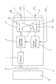
- a dual voltage electrical system is shown with a first electrical system circuit 5 with a supply voltage for the 42 volt consumers connected to this circuit and a second electrical system circuit 3 with a supply voltage of 14 volts. It is understood that this numerical information are provided for your convenience only However, the invention does not restrict the possibility further electrical systems with different voltages.
- the illustrated embodiment relates to an electromechanical Disc brake 10, the brake disc 11 on the Axis of the associated vehicle wheel 12 is attached.
- a as Actuator trained servomotor 1 acts on brake shoes and thus actuates the electromechanical disc brake.
- the servomotor is connected by an upstream power electronics 4, their power supply from the one with the high Voltage of 42 volts equipped electrical system circuit 5 relates.
- the control commands for the power electronics are from a assigned control electronics 2 generates the corresponding Obtains command signals via a BUS line and for Power supply is connected to the 14 V electrical system circuit 3.
- this cross-circuit arrangement 6 for a multi-voltage electrical system either is only available once, with appropriate performance design your switching systems or, if desired or where appropriate, can also be present several times, for example immediately adjacent in close proximity to the corresponding consumers to be able to be arranged.
- the crossover circuit arrangement 6 has corresponding ones Sensors 6a, 6b, the failure or defect of one or capture several electrical system circuits and automatically corresponding Cross-connections to the on-board electrical system circuit that is still active arrange so that there is the possibility of an emergency operation for the power supply of failed electrical system circuits.
- the other cross connection from the 14 V on-board network to the 42nd V electrical system circuit is labeled 3/5 and supplies the Consumers of the 42 V circuit directly with the 14 V voltage of the Vehicle electrical system circuit 3. This is sufficient to provide an emergency running supply of the connected systems.
- any circuit arrangements can be used, for example, purely electronic switches in the form of correspondingly designed in their performance MOS-FET'S, other Power semiconductors or relay circuits in this Trap at the very low frequency to be expected Utilization can be used.
- the sensors 6a, 6b are dispensed with, since at Power failure these relays can be designed that they can then automatically on the respective Toggle crossover connection. It is understood that the Power supply for the crossover circuit arrangement 6 in any case on both or on all existing electrical systems based, so that their functionality at least for so long it is certain how one of the on-board electrical systems is still functional, to which failed electrical systems can be switched.
Landscapes
- Engineering & Computer Science (AREA)
- Power Engineering (AREA)
- Business, Economics & Management (AREA)
- Emergency Management (AREA)
- Valves And Accessory Devices For Braking Systems (AREA)
- Direct Current Feeding And Distribution (AREA)
- Electric Propulsion And Braking For Vehicles (AREA)
- Control Of Multiple Motors (AREA)
Applications Claiming Priority (2)
| Application Number | Priority Date | Filing Date | Title |
|---|---|---|---|
| DE19921451 | 1999-05-08 | ||
| DE1999121451 DE19921451C1 (de) | 1999-05-08 | 1999-05-08 | Bordnetz bei Kraftfahrzeugen |
Publications (2)
| Publication Number | Publication Date |
|---|---|
| EP1052148A2 true EP1052148A2 (fr) | 2000-11-15 |
| EP1052148A3 EP1052148A3 (fr) | 2005-02-16 |
Family
ID=7907547
Family Applications (1)
| Application Number | Title | Priority Date | Filing Date |
|---|---|---|---|
| EP20000108705 Withdrawn EP1052148A3 (fr) | 1999-05-08 | 2000-04-22 | Réseau de bord de véhicule |
Country Status (4)
| Country | Link |
|---|---|
| US (1) | US6455949B1 (fr) |
| EP (1) | EP1052148A3 (fr) |
| JP (1) | JP3419736B2 (fr) |
| DE (1) | DE19921451C1 (fr) |
Families Citing this family (25)
| Publication number | Priority date | Publication date | Assignee | Title |
|---|---|---|---|---|
| DE10122954B4 (de) * | 2000-09-07 | 2016-09-08 | Continental Teves Ag & Co. Ohg | Verfahren und Schaltungsanordnung zur Strom- und Spannungsversorgung von mindestens einem elektrischen Verbraucher in einem Kraftfahrzeug und deren Verwendung in einem elektrischen Bremssystem |
| US6642633B1 (en) * | 2001-06-27 | 2003-11-04 | Yazaki North America, Inc. | Power management assembly |
| DE10149105A1 (de) * | 2001-10-05 | 2003-05-08 | Audi Ag | Verfahren und Vorrichtung zur Regelung der Energieversorgung von Verbrauchern in einem Bordnetz |
| DE10160266A1 (de) | 2001-12-07 | 2003-06-18 | Daimler Chrysler Ag | Verfahren und Anordnung zur Ruhestromversorgung eines Fahrzeugs mit einem Mehrspannungsbordnetz |
| AT500328B1 (de) * | 2002-02-07 | 2010-03-15 | Elin Ebg Traction Gmbh | Fahrzeug mit einem elektrischen antrieb und verfahren zum betrieb eines solchen fahrzeuges |
| DE10322875A1 (de) | 2002-06-11 | 2004-01-08 | Daimlerchrysler Ag | Anordnung zur Spannungsversorgung mehrerer Verbraucher und Steuergerät für ein mindestens zwei Energiespeicher umfassendes Bordnetz |
| JP4089305B2 (ja) * | 2002-06-14 | 2008-05-28 | 株式会社日立製作所 | 車両用電力供給装置 |
| DE10311396A1 (de) | 2003-03-13 | 2004-09-23 | Robert Bosch Gmbh | Vorrichtung für ein Daten- und Energiemanagment in einem Fahrzeug |
| DE10317362B4 (de) * | 2003-04-15 | 2005-10-06 | Siemens Ag | Fahrzeugbordnetz und Verfahren zum Betreiben eines Fahrzeugbordnetzes |
| EP1820699A4 (fr) * | 2004-11-30 | 2015-09-02 | Kayaba Industry Co Ltd | Alimentation de secours |
| DE102005027164A1 (de) * | 2005-06-13 | 2006-12-21 | Robert Bosch Gmbh | Verfahren zum Versorgen von elektrischen Schaltungseinheiten mit elektrischer Energie und Versorgungsvorrichtung zur Durchführung des Verfahrens |
| DE102006010713B4 (de) * | 2006-03-08 | 2010-04-01 | Audi Ag | Bordnetz für ein Fahrzeug und Verfahren zur Energieversorgung eines sicherheitsrelevanten Verbrauchers eines Bordnetzes |
| US20070284939A1 (en) * | 2006-06-12 | 2007-12-13 | Honeywell International | Aircraft electric brake and generator therefor |
| JP4952931B2 (ja) | 2007-08-30 | 2012-06-13 | トヨタ自動車株式会社 | ステアリング装置 |
| DE102010001239A1 (de) * | 2010-01-27 | 2011-07-28 | SB LiMotive Company Ltd., Kyonggi | Batteriesystem für Kraftfahrzeuge mit Hochleistungsverbrauchern |
| DE102010046616A1 (de) | 2010-09-25 | 2012-03-29 | Volkswagen Ag | System und Verfahren zum Versorgen elektrisch betriebener Verbraucher und Kraftfahrzeuge |
| DE102013218576B4 (de) | 2012-09-20 | 2023-08-24 | GM Global Technology Operations LLC (n. d. Ges. d. Staates Delaware) | Fehlerbetrieb-Stromversorgungssystem mit mehreren Energiespeichervorrichtungen |
| JP6092638B2 (ja) * | 2013-01-23 | 2017-03-08 | 矢崎総業株式会社 | 車両用電源制御装置 |
| DE102014203968A1 (de) | 2014-03-05 | 2015-09-10 | Brose Fahrzeugteile Gmbh & Co. Kommanditgesellschaft, Hallstadt | Steuergerät für ein Mehrspannungsbordnetz eines Fahrzeugs |
| DE102014214103A1 (de) * | 2014-07-21 | 2016-01-21 | Robert Bosch Gmbh | Vorrichtung zur Versorgung zumindest eines Verbrauchers |
| DE102015201869A1 (de) * | 2015-02-03 | 2016-08-04 | Brose Fahrzeugteile Gmbh & Co. Kg, Hallstadt | Steuervorrichtung für ein Mehrspannungsbordnetz |
| DE102017205349A1 (de) * | 2017-03-29 | 2018-10-04 | Robert Bosch Gmbh | Bordnetz |
| DE102018210667A1 (de) * | 2018-06-29 | 2020-01-02 | Bayerische Motoren Werke Aktiengesellschaft | Bordnetz eines Kraftfahrzeugs |
| CN109878438B (zh) * | 2019-02-22 | 2021-09-14 | 湖南海博瑞德电智控制技术有限公司 | 用于新能源汽车的电源系统 |
| DE102022206080A1 (de) * | 2022-06-15 | 2023-12-21 | Robert Bosch Gesellschaft mit beschränkter Haftung | Verfahren zum Betreiben einer Rechenanordnung |
Citations (1)
| Publication number | Priority date | Publication date | Assignee | Title |
|---|---|---|---|---|
| DE19651612A1 (de) | 1996-12-12 | 1998-06-18 | Bosch Gmbh Robert | Elektronische Schaltung zur Spannungsversorgung |
Family Cites Families (6)
| Publication number | Priority date | Publication date | Assignee | Title |
|---|---|---|---|---|
| DE3502100C2 (de) * | 1985-01-23 | 1996-04-11 | Wabco Gmbh | Druckmittelbremsanlage für Kraftfahrzeuge |
| JP3039119B2 (ja) * | 1992-03-31 | 2000-05-08 | 日産自動車株式会社 | 車両用電源装置 |
| JP2959657B2 (ja) * | 1993-05-13 | 1999-10-06 | キヤノン株式会社 | 電子機器 |
| US5549984A (en) * | 1994-07-25 | 1996-08-27 | Globe-Union Inc. | Control and indicator circuit for a dual battery system |
| DE19827455C2 (de) * | 1997-07-30 | 2000-03-16 | Siemens Ag | Bremsanlage für ein Kraftfahrzeug |
| US6104103A (en) * | 1998-05-08 | 2000-08-15 | Ingalls Shipbuilding, Inc. | Simultaneous power supply source |
-
1999
- 1999-05-08 DE DE1999121451 patent/DE19921451C1/de not_active Expired - Lifetime
-
2000
- 2000-04-22 EP EP20000108705 patent/EP1052148A3/fr not_active Withdrawn
- 2000-05-08 JP JP2000134520A patent/JP3419736B2/ja not_active Expired - Fee Related
- 2000-05-08 US US09/567,107 patent/US6455949B1/en not_active Expired - Fee Related
Patent Citations (1)
| Publication number | Priority date | Publication date | Assignee | Title |
|---|---|---|---|---|
| DE19651612A1 (de) | 1996-12-12 | 1998-06-18 | Bosch Gmbh Robert | Elektronische Schaltung zur Spannungsversorgung |
Also Published As
| Publication number | Publication date |
|---|---|
| US6455949B1 (en) | 2002-09-24 |
| JP2001008360A (ja) | 2001-01-12 |
| DE19921451C1 (de) | 2000-11-30 |
| JP3419736B2 (ja) | 2003-06-23 |
| EP1052148A3 (fr) | 2005-02-16 |
Similar Documents
| Publication | Publication Date | Title |
|---|---|---|
| DE19921451C1 (de) | Bordnetz bei Kraftfahrzeugen | |
| EP3818605B1 (fr) | Réseau de bord pour un véhicule ainsi que véhicule | |
| DE19548392C2 (de) | Bremsanlage für ein Kraftfahrzeug | |
| EP1302371B1 (fr) | Alimentation redondante d'énergie pour des comsommateurs de sécurité dans un réseau de bord | |
| DE10326294B4 (de) | Stromversorgungssystem für ein Fahrzeug | |
| DE10235788B4 (de) | Elektrisches Verbindungssystem für ein Kraftfahrzeug | |
| WO2006082125A1 (fr) | Reseau de bord pour des consommateurs lies a la securite | |
| DE10160266A1 (de) | Verfahren und Anordnung zur Ruhestromversorgung eines Fahrzeugs mit einem Mehrspannungsbordnetz | |
| DE102005005236B4 (de) | Fahrzeug mit einem Bordnetz und einer Mehrzahl von elektrischen Lasten | |
| WO2008138549A2 (fr) | Montage destiné à alimenter en courant des appareils de commande dans des véhicules à moteur | |
| WO2025157348A1 (fr) | Procédé de fonctionnement d'une charge électrique dans un véhicule | |
| EP4373713A1 (fr) | Dispositif de distribution de courant et véhicule automobile | |
| WO2018149663A1 (fr) | Circuit destiné à mettre en œuvre une comparaison | |
| DE19941481B4 (de) | Elektrisch gesteuertes, dezentrales Steuersystem in einem Fahrzeug | |
| DE10317362B4 (de) | Fahrzeugbordnetz und Verfahren zum Betreiben eines Fahrzeugbordnetzes | |
| EP3197726B1 (fr) | Réseau de bord | |
| DE2942987A1 (de) | Einrichtung zur steuerung und verteilung elektrischer leistung in einem motorfahrzeug | |
| WO2007020183A1 (fr) | Reseau de bord d'un vehicule hybride comprenant des consommateurs critiques en termes de securite | |
| DE102024000970A1 (de) | Elektrisches Bordnetz für ein Fahrzeug | |
| EP3190675A1 (fr) | Procédé de couplage d'un consommateur | |
| WO2017118554A1 (fr) | Réseau de bord | |
| DE102024002043B4 (de) | Elektrisches Bordnetz für ein Fahrzeug und Verfahren zum Betrieb eines Bordnetzes | |
| DE102020117631A1 (de) | Redundante Energieversorgung für autonome Fahrzeuge | |
| DE102024103921B3 (de) | Redundante Energieversorgung für elektrische Verbraucher | |
| DE19908061B4 (de) | Energieversorgungseinrichtung für eine elektrisch betätigbare Fahrzeugbremse |
Legal Events
| Date | Code | Title | Description |
|---|---|---|---|
| PUAI | Public reference made under article 153(3) epc to a published international application that has entered the european phase |
Free format text: ORIGINAL CODE: 0009012 |
|
| AK | Designated contracting states |
Kind code of ref document: A2 Designated state(s): AT BE CH CY DE DK ES FI FR GB GR IE IT LI LU MC NL PT SE |
|
| AX | Request for extension of the european patent |
Free format text: AL;LT;LV;MK;RO;SI |
|
| PUAL | Search report despatched |
Free format text: ORIGINAL CODE: 0009013 |
|
| AK | Designated contracting states |
Kind code of ref document: A3 Designated state(s): AT BE CH CY DE DK ES FI FR GB GR IE IT LI LU MC NL PT SE |
|
| AX | Request for extension of the european patent |
Extension state: AL LT LV MK RO SI |
|
| 17P | Request for examination filed |
Effective date: 20050125 |
|
| AKX | Designation fees paid |
Designated state(s): DE FR GB IT SE |
|
| STAA | Information on the status of an ep patent application or granted ep patent |
Free format text: STATUS: THE APPLICATION HAS BEEN WITHDRAWN |
|
| 18W | Application withdrawn |
Effective date: 20060503 |