EP1052149A2 - Procédé de fonctionnement d'une installation de sécurité de véhicule - Google Patents
Procédé de fonctionnement d'une installation de sécurité de véhicule Download PDFInfo
- Publication number
- EP1052149A2 EP1052149A2 EP00109483A EP00109483A EP1052149A2 EP 1052149 A2 EP1052149 A2 EP 1052149A2 EP 00109483 A EP00109483 A EP 00109483A EP 00109483 A EP00109483 A EP 00109483A EP 1052149 A2 EP1052149 A2 EP 1052149A2
- Authority
- EP
- European Patent Office
- Prior art keywords
- battery
- vehicle
- switching logic
- electrical system
- signal
- Prior art date
- Legal status (The legal status is an assumption and is not a legal conclusion. Google has not performed a legal analysis and makes no representation as to the accuracy of the status listed.)
- Withdrawn
Links
- 238000009434 installation Methods 0.000 title 1
- 238000011017 operating method Methods 0.000 title 1
- 238000000034 method Methods 0.000 claims abstract description 16
- 238000000926 separation method Methods 0.000 claims description 14
- 239000007858 starting material Substances 0.000 claims description 12
- 230000005611 electricity Effects 0.000 claims description 6
- 238000002847 impedance measurement Methods 0.000 claims description 4
- 230000036961 partial effect Effects 0.000 claims description 4
- 230000004913 activation Effects 0.000 claims 1
- 238000002955 isolation Methods 0.000 abstract 1
- 230000006378 damage Effects 0.000 description 10
- 230000002441 reversible effect Effects 0.000 description 7
- 230000001960 triggered effect Effects 0.000 description 6
- 238000004519 manufacturing process Methods 0.000 description 4
- 230000008901 benefit Effects 0.000 description 3
- 238000002485 combustion reaction Methods 0.000 description 3
- 230000008569 process Effects 0.000 description 3
- QAOWNCQODCNURD-UHFFFAOYSA-N Sulfuric acid Chemical compound OS(O)(=O)=O QAOWNCQODCNURD-UHFFFAOYSA-N 0.000 description 2
- 238000005516 engineering process Methods 0.000 description 2
- 230000002829 reductive effect Effects 0.000 description 2
- 230000004044 response Effects 0.000 description 2
- 230000002459 sustained effect Effects 0.000 description 2
- 230000008859 change Effects 0.000 description 1
- 238000006243 chemical reaction Methods 0.000 description 1
- 238000000354 decomposition reaction Methods 0.000 description 1
- 238000011161 development Methods 0.000 description 1
- 230000018109 developmental process Effects 0.000 description 1
- 238000010586 diagram Methods 0.000 description 1
- 230000000694 effects Effects 0.000 description 1
- 239000002360 explosive Substances 0.000 description 1
- 239000000446 fuel Substances 0.000 description 1
- 230000006870 function Effects 0.000 description 1
- 230000002401 inhibitory effect Effects 0.000 description 1
- 238000005259 measurement Methods 0.000 description 1
- 230000006386 memory function Effects 0.000 description 1
- 238000012544 monitoring process Methods 0.000 description 1
- 230000003287 optical effect Effects 0.000 description 1
- 210000000056 organ Anatomy 0.000 description 1
- 238000013021 overheating Methods 0.000 description 1
- 230000002093 peripheral effect Effects 0.000 description 1
- 230000002265 prevention Effects 0.000 description 1
- 230000002035 prolonged effect Effects 0.000 description 1
- 230000001681 protective effect Effects 0.000 description 1
- 238000012546 transfer Methods 0.000 description 1
- 230000002618 waking effect Effects 0.000 description 1
- 239000002699 waste material Substances 0.000 description 1
Images

Classifications
-
- B—PERFORMING OPERATIONS; TRANSPORTING
- B60—VEHICLES IN GENERAL
- B60R—VEHICLES, VEHICLE FITTINGS, OR VEHICLE PARTS, NOT OTHERWISE PROVIDED FOR
- B60R16/00—Electric or fluid circuits specially adapted for vehicles and not otherwise provided for; Arrangement of elements of electric or fluid circuits specially adapted for vehicles and not otherwise provided for
- B60R16/02—Electric or fluid circuits specially adapted for vehicles and not otherwise provided for; Arrangement of elements of electric or fluid circuits specially adapted for vehicles and not otherwise provided for electric constitutive elements
- B60R16/03—Electric or fluid circuits specially adapted for vehicles and not otherwise provided for; Arrangement of elements of electric or fluid circuits specially adapted for vehicles and not otherwise provided for electric constitutive elements for supply of electrical power to vehicle subsystems or for
Definitions
- the invention relates to a method for operating a Safety device for motor vehicles according to the Preamble of claim 1.
- a known safety circuit of this type in the form a disconnecting device for motor vehicles goes out DE 33 27 532 A1. It primarily speaks electrical commands from an emergency command transmitter, is so switch remotely and enables a separation of the Battery from vehicle electrical system; but not only in Emergencies, but also when the vehicle is turned off. Such a stand switch due to a prevention circuit only at motor stopped or if none other electricity consumers in motor vehicles are switched on. This is problematic however, that the control circuit even when done Vehicle electrical system disconnection continues to maintain their Operational readiness remains connected to the battery and consumes electricity, so for a longer one Vehicle standstill or overseas transport not can be used. Switching off the battery from Finally, the electrical system is carried out via self-holding relays, which may occur with the very high currents occurring here Get contact problems or to Contact sticking tend.
- Control units In modern motor vehicles, the number of electric vehicles is increasing Control units according to the number of to an on-board network of hanging consumers, so that to increase operational safety, the control units usually with an in-vehicle bus system are networked and in a kind of ring line from one central control device digital switching signals received by means of microprocessors in the control units decrypted and in appropriate commands to the immediately adjacent recipients are implemented.
- CAN Controller Area Network
- Control devices or those arranged in them Microprocessors after switching off the vehicle one depending on the type of control unit Delay time into a sleep or sleep mode. In this state, the quiescent current consumption is the Control units relatively small, but in total can but permanently on a vehicle battery polluting current of some 100 mA, in particular if there is still an armed monitoring system come in addition.
- a vehicle with a heavily discharged battery is often put back into operation by a third-party start, that is to say by starting a second battery, which usually comes from a third-party vehicle, in parallel with the discharged vehicle battery.
- a third-party start that is to say by starting a second battery, which usually comes from a third-party vehicle, in parallel with the discharged vehicle battery.
- the poles it is not uncommon for the poles to be mixed up, particularly at night, which can result in sustained damage not only to the vehicle battery, which is already severely weakened, but also to the electrical equipment and control devices in the vehicle, i.e. the entire vehicle electrical system, including the generator and generator diodes, and the electronics .
- the problem with motor vehicle electrical systems is therefore the (Automatic) protection of the built-in vehicle battery before deep discharge, as is the case with overseas transport, if the vehicle is at a standstill for a longer period of time heavy load and thus corresponding discharge Protection of the vehicle electrical system and its can occur Components before polarity reversal, at least disconnection from crash-prone electrical vehicle components and Lines in a possible accident as well as eventually the need to change the basic setting in the event of a separation between vehicle electrical system and battery again to manufacture, i.e. the vehicle back into one Bring normal condition.
- DE 42 11 578 C1 describes a battery disconnection device for motor vehicles with a battery disconnect switch from the battery compartment manually and from Driver's seat off with a safety main switch can be operated remotely. Before a possible Opening the battery isolating switch must all first ignition-switched consumer switched off and one Engine shutdown can be initiated.
- Another battery disconnect switch known from DE 33 03 185 A1 has a handle on the one hand arbitrary manual switching on and off using in a sleeve arranged cam tracks, on the other can also be actuated in the switch-off direction another source of power, for example one Trigger an explosive cartridge that is triggered by a pulse Can be triggered depending on the response of a fire detector is.
- Reverse polarity protection devices are also available, for example Battery chargers or when connecting batteries On-board networks of motor vehicles from DE 42 31 970 C2 or DE 196 03 117 A1.
- the known reverse polarity protection arrangements for a Battery charging system and / or an electrical system for Motor vehicles are usually based on the fact that a Sensor circuit is provided, the polarity of the battery to be detected and connected to a charger or to the vehicle electrical system only for example by closing a switch allows if the polarity is correct.
- the reverse polarity protection circuit for a battery charger works in such a way that a microprocessor detecting the polarity reversal Connection point for the positive pole of the battery to be charged positive voltage itself via a voltage divider is supplied in the event that the microprocessor on one correct polarity can't see for sure. It actually results in a wrong polarity over this voltage divider then one shifted so strongly towards negative values, from Microprocessor measuring voltage to be evaluated Voltage divider that a for reverse polarity correct polarity reversal message and corresponding Measures taken, for example polarity reversal of the connections can be made.
- DE-AS 1 086 322 is an electrical one High-voltage switch known in which an axial Movable pin-shaped switch contact and two with this provided cooperative fixed contacts are. Both the switch contact and the fixed one Contacts are arranged in a control room, which by is surrounded by a double-walled jacket. This is ensured that due to the metallic Condition of the outer wall of the control room in any case, parts with a high field strength outside the Switch room. Relationships with one with Low voltage battery disconnect switches are unavailable.
- the switch-off means can be, for example electromagnetic actuator or one Detonator.
- the invention is based on the object, once for it to worry about that for a variety of reasons shutdown to be carried out, i.e. a separation of the Battery from the vehicle electrical system is quick and easy is, in order to avoid deep discharge of the Battery also the organ responsible for switching itself is disconnected from the electrical system, but on the other hand ensure that the vehicle is put into operation, thus the connection of the battery to the vehicle electrical system without greater effort and assembly possible again at any time is.
- the safety device consisting of multi-stage, motor-driven Battery disconnect switch, switching logic and associated Sensor technology
- a variety of essential tasks assign i.e. that of such a multi-stage Disconnectors optimal security options to use and at the same time for the vehicle user to provide a high level of user comfort.
- the arrangement of a starting aid base is also advantageous in the area of the high-current disconnector, the as a motor switch is part of the safety device.
- the starting point can be e.g. with the positive pole one Auxiliary battery, for example via a jump lead, or with another, a correspondingly high one Starting aid device providing starting current, for example one fed with AC voltage, mobile rectifier circuit, are connected or can itself serve as a jump start for a third-party vehicle.
- the vehicle structure shown in an oval frame Fig. 1 leaves a battery 10 and one with the battery recognize connected safety device 11.
- the Safety device 11 is via a connection connection 20 with the battery, via a connection connector 21 with a jump start 15, about a connection terminal 19 with such electrical Vehicle components connected in an accident or crash-prone area of the vehicle, such as for example generator 13 and starter 12, and over a connection connection 22 to the vehicle electrical system 14 connected.
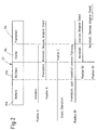
- These connection connections are are all high-current connections that (see Fig. 2) directly with the corresponding contact assignments 19a for components at risk of crash, 20a for the battery, 21a for the jump start base and 22a for the electrical system of the battery disconnect switch are connected, which is shown in Fig. 1 as motor switch 16 together with associated Switching logic 17 and impedance / current sensor 18 in the separately drawn border of the safety device is shown.
- FIG. 2 are those with those mentioned earlier Components connected switch contacts or Contact assignments 19a, 20a, 21a and 22a of the motor switch 16 part of an example and preferably tubular Contact carrier 23, the individual Switch contacts via a, not shown, motor-driven contact bridge of the a total of 16 working as a motor switch Battery disconnect switch in basically any way can be interconnected.
- Some of the Possible switching connections are shown in Fig. 2 below of the contact carrier 23 in the form of thick solid Lines shown, the individual positions A, B, C, B1, B2, B3 on realized by the contact bridge indicate possible switching connections, in connection with the appropriate label.
- Such a manual disconnection of the battery takes place for example, by entering an operator's command via a corresponding input unit 40 longer standstill of the vehicle, for example shipping or production, while a stay in the workshop and the like
- the opening of the battery isolating switch accordingly Separation of the battery from the vehicle electrical system and from the starter / generator circuit (Position B in Fig. 2, possibly also Subitem B2 or B3) can be accessed via a menu for example in an instrument cluster of the vehicle respectively.
- the menu item should be at least one low operating level and, for example, only above a code to be accessible.
- left column is used as security against unintentional opening a vehicle operating signal during operation of the vehicle used, for example one at terminal 15 or terminal 15R of the ignition lock 36, which follows as representative of the existing operation of the Viewed vehicle and referred to as Klemme15 signal will be used.
- the switching logic 17 separates the Battery only if the Kl15 signal is not is present.
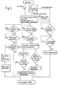
- the time-delayed shutdown Tx takes place with a Time constants, for example, between 30 seconds and 2 Minutes, whereby to delay the turn off to identify during this time delay acoustic or optical warning signal is triggered. This alarm signal disappears when disconnection is completed the battery. So on the one hand for the Operator given feedback that the function was triggered. There is also for the operator the possibility of the vehicle during this time to leave, and finally you get through that The warning message ends with clear information that the battery has actually been disconnected is. Since the labels in the blocks of the 3 speaks for itself, does not need to go into this again separately become.
- the submenu from which the Disconnect command can be called also as standard (default) to be set so that for calling up the menu item no time is lost.
- the manual disconnect command in the factory to call up (i.e. permanently discontinued) and in the case of waste the switch 15 to the switch with a time delay to open. After the transportation process is finished this mode is then canceled.
- the automatic Shutdown is only permitted if none Terminal15 signal is present, so the vehicle is not is in operation. Furthermore, a delay time for considered the shutdown, for example should be at least 10 minutes. For this time undervoltage if terminal 15 or Terminal15R signal present. If this is the case, separate the switching logic 17 automatically removes the battery from the vehicle electrical system 14, including the starter area so that the Disconnector according to FIG. 2 preferably in the Position B3 is transferred.
- Switching off the battery in the event of a pre-crash or Crash signals can only occur when the terminal is connected 15 / 15R signal.
- the terminal is connected 15 / 15R signal.
- the starter / generator circuit in the area at risk of crash Separated consumers. In this state it is Vehicle still roadworthy, and all other safety devices are still fully functional.
- a partial shutdown also takes place in any case always in the area of crash-prone components, if via the impedance or current sensor 18 in the Connecting line 19 to these components excessive current, which indicates a short circuit, is measured.
- the switching logic 17 also detects via a sensor 15 the potential at in the standard position A normally not connected to the rest of the vehicle components Jump start base 15. This results at this jump start base 15 a potential which is more positive or is at least equal to the potential at the positive battery terminal, then the jump start base 15 is preferred automatically with at least the starter / generator circuit connected, i.e. the disconnector is in the appropriate Position B2 of Fig. 2 transferred. But it is also a switchover of the battery isolating switch to the Position B and finally position B1 of the Fig.
- position B1 Parallel connection of the external battery to your own Vehicle battery
- position B to select the Loads of external batteries can be reduced by free choice set in the menu by the operator, or it is in the switching logic 17 from the outset programmed accordingly.
- the Switching logic 17 the contact to the external starting point 15 automatically disconnected if the current flow from the There was a third-party vehicle for your own vehicle, for which Current flow from the generator, which is yes via the current sensor 18th is detected in line 19, in their own or in the External battery or a "motor running" signal is used can be.
- the jump start base is preferred via a high-resistance resistor (pull-down resistor) connected to ground so that voltage changes on Foreign start base 15 can be evaluated in a defined manner can.
- a high-resistance resistor pulse-down resistor
- An automatic switchover via the switching logic 17 is also possible in the event that a third-party vehicle Jump start is given.
- This is your own Vehicle battery connected to the jump start base i.e. the battery disconnect switch is in position B1 of Fig. 2 transferred.
- a separation after one predefined time delay can take place automatically. If the switch-on condition still exists after that, then the own battery is put back on the Jump start base 15 activated.
Landscapes
- Engineering & Computer Science (AREA)
- Mechanical Engineering (AREA)
- Electric Propulsion And Braking For Vehicles (AREA)
- Power-Operated Mechanisms For Wings (AREA)
Applications Claiming Priority (2)
| Application Number | Priority Date | Filing Date | Title |
|---|---|---|---|
| DE19922331A DE19922331C1 (de) | 1999-05-14 | 1999-05-14 | Verfahren zum Betrieb einer Sicherheitseinrichtung für Kraftfahrzeuge |
| DE19922331 | 1999-05-14 |
Publications (2)
| Publication Number | Publication Date |
|---|---|
| EP1052149A2 true EP1052149A2 (fr) | 2000-11-15 |
| EP1052149A3 EP1052149A3 (fr) | 2005-03-16 |
Family
ID=7908124
Family Applications (1)
| Application Number | Title | Priority Date | Filing Date |
|---|---|---|---|
| EP00109483A Withdrawn EP1052149A3 (fr) | 1999-05-14 | 2000-05-04 | Procédé de fonctionnement d'une installation de sécurité de véhicule |
Country Status (3)
| Country | Link |
|---|---|
| US (1) | US6433442B1 (fr) |
| EP (1) | EP1052149A3 (fr) |
| DE (1) | DE19922331C1 (fr) |
Cited By (3)
| Publication number | Priority date | Publication date | Assignee | Title |
|---|---|---|---|---|
| DE10322506B4 (de) * | 2002-05-31 | 2006-04-20 | Sanyo Electric Co., Ltd. | Stromversorgungsgerät für ein Kraftfahrzeug |
| WO2013079310A1 (fr) * | 2011-11-30 | 2013-06-06 | Bayerische Motoren Werke Aktiengesellschaft | Circuiterie et procédé pour éviter des décharges totales d'un accumulateur d'énergie dans un réseau de bord de véhicule automobile |
| CN107438534A (zh) * | 2015-04-21 | 2017-12-05 | 大众汽车有限公司 | 用于车辆的高压能量系统的方法和装置 |
Families Citing this family (26)
| Publication number | Priority date | Publication date | Assignee | Title |
|---|---|---|---|---|
| US7729831B2 (en) | 1999-07-30 | 2010-06-01 | Oshkosh Corporation | Concrete placement vehicle control system and method |
| DE10047791A1 (de) * | 2000-09-18 | 2002-03-28 | Volkswagen Ag | Verpolschutz für Fremdstartpol |
| DE10061023A1 (de) * | 2000-12-08 | 2002-06-13 | Bayerische Motoren Werke Ag | Schalter in Fahrzeugen |
| US7277782B2 (en) | 2001-01-31 | 2007-10-02 | Oshkosh Truck Corporation | Control system and method for electric vehicle |
| US20030080621A1 (en) * | 2001-10-26 | 2003-05-01 | Kirk John B. | Automotive electrical system protection device |
| US20030107861A1 (en) * | 2001-12-06 | 2003-06-12 | Hazelton Lawrence Dean | Method and apparatus for disconnecting a battery |
| US7412307B2 (en) * | 2002-08-02 | 2008-08-12 | Oshkosh Truck Corporation | Refuse vehicle control system and method |
| US7353897B2 (en) * | 2003-07-23 | 2008-04-08 | Fernandez Dennis S | Telematic method and apparatus with integrated power source |
| DE10358249A1 (de) * | 2003-12-09 | 2005-07-07 | Volkswagen Ag | Bordnetz für Kraftfahrzeuge |
| DE102004030699A1 (de) * | 2004-06-25 | 2006-01-19 | Bayerische Motoren Werke Ag | Vorrichtung zur Spannungsversorgung eines Steuergeräts |
| DE102004040302A1 (de) * | 2004-08-19 | 2006-03-09 | Siemens Ag | Fernüberwachung von elektrischen Systemen |
| US7422293B2 (en) * | 2005-07-26 | 2008-09-09 | Ford Global Technologies, Llc | System and a method for dissipating voltage in an electrical circuit of a vehicle |
| US8179230B2 (en) * | 2005-12-29 | 2012-05-15 | Renault Trucks | Method for passive keyless entry of a motor vehicle especially of an industrial vehicle |
| DE102006004337B4 (de) * | 2006-01-31 | 2015-08-13 | Lear Coporation Electrical and Electronics GmbH & Co. KG | Stromverbindungsvorrichtung für eine Batteriepolklemme |
| DE102006032879A1 (de) * | 2006-07-15 | 2008-01-17 | Daimler Ag | Vorrichtung und Verfahren zur Auslösung eines aktiv angesteuerten Trennelementes |
| DE102007026165A1 (de) * | 2007-06-04 | 2008-12-11 | Ipgate Ag | Schaltvorrichtung für Bordnetz eines Kraftfahrzeuges |
| ES2381704B1 (es) * | 2009-09-23 | 2013-05-08 | Cablerias Auto, S.L | Cable de bateria inteligente |
| DE102012100866A1 (de) * | 2012-02-02 | 2013-08-08 | Vorwerk & Co. Interholding Gmbh | Verfahren zur Ausbildung einer Transportsicherung sowie akkubetriebenes Elektrogerät |
| US20130264325A1 (en) * | 2012-04-04 | 2013-10-10 | GM Global Technology Operations LLC | Remote high voltage switch for controlling a high voltage heater located inside a vehicle cabin |
| US9845191B2 (en) | 2013-08-02 | 2017-12-19 | Oshkosh Corporation | Ejector track for refuse vehicle |
| DE102013015713B4 (de) | 2013-09-20 | 2017-02-09 | Audi Ag | Kraftfahrzeug-Hochvoltsystem mit Schutz bei blockierten Schaltschützen und Verfahren zum Betreiben eines derartigen Kraftfahrzeugs |
| DE102014200096A1 (de) * | 2014-01-08 | 2015-07-09 | Robert Bosch Gmbh | Batteriemanagementsystem zum Überwachen und Regeln des Betriebs einer Batterie und Batteriesystem mit einem solchen Batteriemanagementsystem |
| DE102014214594A1 (de) | 2014-07-24 | 2016-01-28 | Robert Bosch Gmbh | Verfahren zum Betreiben eines Assistenzsystems eines Fahrzeugs mit mindestens einem elektrischen Energiespeicher |
| EP3095647B1 (fr) * | 2015-05-19 | 2017-05-17 | Autoliv Development AB | Mécanismes de sécurité d'adaptation d'un système de sécurité de véhicule |
| US20170203666A1 (en) * | 2016-01-19 | 2017-07-20 | Ford Global Technologies, Llc | Battery charging system and servicing method |
| CN105513488A (zh) * | 2016-02-29 | 2016-04-20 | 常州机电职业技术学院 | 挖掘机电气系统实验教学仪器设备 |
Citations (7)
| Publication number | Priority date | Publication date | Assignee | Title |
|---|---|---|---|---|
| DE1086322B (de) | 1956-02-15 | 1960-08-04 | Iacoqia Nv | Elektrischer Schalter fuer hohe Spannungen |
| DE3303185A1 (de) | 1982-02-04 | 1983-09-15 | Dafo Brand AB, Tyresö | Batterietrennschalter |
| DE3327532A1 (de) | 1983-07-30 | 1985-02-07 | Iveco Magirus AG, 7900 Ulm | Trennschalteinrichtung fuer kraftfahrzeuge |
| DE3402372A1 (de) | 1984-01-25 | 1985-08-01 | Doduco KG Dr. Eugen Dürrwächter, 7530 Pforzheim | Elektrisches schaltelement |
| DE4211578C1 (en) | 1992-04-07 | 1993-04-29 | Mercedes-Benz Aktiengesellschaft, 7000 Stuttgart, De | Vehicle battery isolating circuit - has switch to isolate battery from generator, operable from engine compartment, and second switch near driver seat to remotely actuate first |
| DE4231970C2 (de) | 1992-09-24 | 1995-02-16 | Bsg Schalttechnik | Batterieladegerät |
| DE19603117A1 (de) | 1995-02-17 | 1996-08-29 | Int Rectifier Corp | Verpolungs-Schutzschaltung |
Family Cites Families (34)
| Publication number | Priority date | Publication date | Assignee | Title |
|---|---|---|---|---|
| US3536876A (en) * | 1967-12-06 | 1970-10-27 | William R Lastinger | Quick disconnect battery apparatus |
| DE2732794A1 (de) | 1977-07-20 | 1979-02-08 | Norka Norddeutsche Kunststoff | Schutzanordnung fuer akkumulator gegen tiefentladung |
| DE2836041A1 (de) * | 1978-08-17 | 1980-02-28 | Bosch Gmbh Robert | Verpolschutzanordnung |
| DE2919021A1 (de) * | 1979-05-11 | 1980-11-20 | Bosch Gmbh Robert | Verpolschutzanordnung fuer ein batterieladesystem |
| DE2919022A1 (de) * | 1979-05-11 | 1980-11-20 | Bosch Gmbh Robert | Verpolschutzanordnung fuer ein batterieladesystem |
| US4563968A (en) | 1982-05-14 | 1986-01-14 | Joseph Wawrzynek | Boat with improved hull |
| US4798968A (en) * | 1987-05-15 | 1989-01-17 | Deem James R | Battery disconnect apparatus |
| EP0305610A1 (fr) * | 1987-09-01 | 1989-03-08 | Vbh Investments (Proprietary) Limited | Dispositif de connexion de borne de batterie |
| DE3827045A1 (de) * | 1988-08-10 | 1990-02-22 | Ullmann Ulo Werk | Verpolungsschutzeinrichtung fuer akkuladegeraete |
| DE3841769C1 (en) * | 1988-12-12 | 1990-06-07 | Juergen 8014 Neubiberg De Wemhoener | Circuit for ensuring the provision of starting energy in motor vehicles with internal combustion engines |
| US5200877A (en) * | 1990-04-04 | 1993-04-06 | Baton Labs, Inc. | Battery protection system |
| DE4028242C2 (de) * | 1990-09-06 | 1997-08-07 | Bayerische Motoren Werke Ag | Bordnetz für Kraftfahrzeuge |
| US5142162A (en) * | 1990-12-11 | 1992-08-25 | General Motors Corporation | Motor vehicle battery discharge current control |
| DE4040405A1 (de) * | 1990-12-17 | 1992-07-02 | Daimler Benz Ag | Entladeschutzschaltung fuer einen durch verbraucher belastbaren stromspeicher eines kraftfahrzeugs |
| US5170151A (en) * | 1991-02-21 | 1992-12-08 | Hochstein Peter A | Method and assembly for disconnecting a battery from its operating system |
| DE4110240C1 (en) * | 1991-03-28 | 1992-10-08 | Mercedes-Benz Aktiengesellschaft, 7000 Stuttgart, De | Vehicle current path protection device - separates battery from load upon occurrence of electrical fault |
| DE4137146A1 (de) * | 1991-11-12 | 1993-05-13 | Kern Johann Dipl Ing | Verfahren zur verhinderung der unabsichtlichen entladung des akkumulators einer transportvorrichtung, z.b. eines kfz und vorrichtung nach diesem verfahren |
| DE9216774U1 (de) * | 1991-12-10 | 1993-05-27 | Bouchier, France | Fernbedientes Batterieschloß |
| DE9115293U1 (de) * | 1991-12-10 | 1992-02-20 | Bouchier, France, Parcent, Alicante | Batterieschloß |
| US5272386A (en) * | 1992-02-14 | 1993-12-21 | Kephart David A | Programmable timer power switch unit with emergency override reset |
| DE9212878U1 (de) * | 1992-09-24 | 1992-11-05 | BSG-Schalttechnik GmbH & Co KG, 7460 Balingen | Batterieladegerät |
| US5321389A (en) * | 1992-11-27 | 1994-06-14 | Echlin, Incorporated | Battery charge monitor |
| JP2815081B2 (ja) * | 1993-02-18 | 1998-10-27 | 矢崎総業株式会社 | バッテリ間接続用コネクタ装置 |
| US5691619A (en) * | 1994-10-31 | 1997-11-25 | Vingsbo; Stefan G. | Automatic safety switch for preventing accidental battery discharge |
| US5693986A (en) * | 1995-06-12 | 1997-12-02 | Chrysler Corporation | Method and device for disconnecting loads from a motor vehicle body |
| DE19606448A1 (de) * | 1996-02-21 | 1997-08-28 | Bayerische Motoren Werke Ag | Batterie-Kabelklemme für Fahrzeuge |
| US6066899A (en) * | 1996-08-01 | 2000-05-23 | Power Technics, Inc. | Resetable battery drain limitation circuit with complementary dual voltage setpoints |
| GB9701936D0 (en) * | 1997-01-30 | 1997-03-19 | Delphi Automotive Systems Gmbh | Battery protection system |
| JP3423577B2 (ja) * | 1997-06-18 | 2003-07-07 | 古河電気工業株式会社 | バッテリー上がり防止機能を備えた車両用電源制御装置 |
| GB9800589D0 (en) * | 1998-01-13 | 1998-03-11 | Delphi Automotive Systems Gmbh | Battery disconnection system |
| US6198995B1 (en) * | 1998-03-31 | 2001-03-06 | Lear Automotive Dearborn, Inc. | Sleep mode for vehicle monitoring system |
| CA2262962C (fr) * | 1998-05-29 | 2003-04-29 | Myung Soon Bae | Dispositif d'interruption automatique du courant en cas d'urgence |
| DE69912711T2 (de) * | 1998-09-24 | 2004-04-15 | Delphi Technologies, Inc., Troy | Batterieabkopplungssystem |
| US6201318B1 (en) * | 1999-02-02 | 2001-03-13 | Clairmont | Headlight warning system |
-
1999
- 1999-05-14 DE DE19922331A patent/DE19922331C1/de not_active Expired - Fee Related
-
2000
- 2000-05-04 EP EP00109483A patent/EP1052149A3/fr not_active Withdrawn
- 2000-05-11 US US09/569,082 patent/US6433442B1/en not_active Expired - Fee Related
Patent Citations (7)
| Publication number | Priority date | Publication date | Assignee | Title |
|---|---|---|---|---|
| DE1086322B (de) | 1956-02-15 | 1960-08-04 | Iacoqia Nv | Elektrischer Schalter fuer hohe Spannungen |
| DE3303185A1 (de) | 1982-02-04 | 1983-09-15 | Dafo Brand AB, Tyresö | Batterietrennschalter |
| DE3327532A1 (de) | 1983-07-30 | 1985-02-07 | Iveco Magirus AG, 7900 Ulm | Trennschalteinrichtung fuer kraftfahrzeuge |
| DE3402372A1 (de) | 1984-01-25 | 1985-08-01 | Doduco KG Dr. Eugen Dürrwächter, 7530 Pforzheim | Elektrisches schaltelement |
| DE4211578C1 (en) | 1992-04-07 | 1993-04-29 | Mercedes-Benz Aktiengesellschaft, 7000 Stuttgart, De | Vehicle battery isolating circuit - has switch to isolate battery from generator, operable from engine compartment, and second switch near driver seat to remotely actuate first |
| DE4231970C2 (de) | 1992-09-24 | 1995-02-16 | Bsg Schalttechnik | Batterieladegerät |
| DE19603117A1 (de) | 1995-02-17 | 1996-08-29 | Int Rectifier Corp | Verpolungs-Schutzschaltung |
Cited By (5)
| Publication number | Priority date | Publication date | Assignee | Title |
|---|---|---|---|---|
| DE10322506B4 (de) * | 2002-05-31 | 2006-04-20 | Sanyo Electric Co., Ltd. | Stromversorgungsgerät für ein Kraftfahrzeug |
| WO2013079310A1 (fr) * | 2011-11-30 | 2013-06-06 | Bayerische Motoren Werke Aktiengesellschaft | Circuiterie et procédé pour éviter des décharges totales d'un accumulateur d'énergie dans un réseau de bord de véhicule automobile |
| CN107438534A (zh) * | 2015-04-21 | 2017-12-05 | 大众汽车有限公司 | 用于车辆的高压能量系统的方法和装置 |
| EP3286032B1 (fr) * | 2015-04-21 | 2020-05-06 | Volkswagen Aktiengesellschaft | Procede et dispositif pour un systeme energetique haute tension d'un vehicule |
| US10737576B2 (en) | 2015-04-21 | 2020-08-11 | Volkswagen Aktiengesellschaft | Method and device for a high-voltage energy system of a vehicle |
Also Published As
| Publication number | Publication date |
|---|---|
| US6433442B1 (en) | 2002-08-13 |
| EP1052149A3 (fr) | 2005-03-16 |
| DE19922331C1 (de) | 2000-11-09 |
Similar Documents
| Publication | Publication Date | Title |
|---|---|---|
| DE19922331C1 (de) | Verfahren zum Betrieb einer Sicherheitseinrichtung für Kraftfahrzeuge | |
| EP1600337B1 (fr) | Coupe-circuit électronique pour batterie | |
| DE102005056947B4 (de) | Fahrzeugsicherheitssystem | |
| EP0897208B1 (fr) | Système de sécurité, par exemple pour système de freins électrique ou système de direction électrique | |
| WO2001036232A1 (fr) | Systeme a deux batteries | |
| EP1144224A2 (fr) | Reseau de bord a batterie, avec coupe-circuit de securite | |
| DE4211578C1 (en) | Vehicle battery isolating circuit - has switch to isolate battery from generator, operable from engine compartment, and second switch near driver seat to remotely actuate first | |
| EP3599125A1 (fr) | Réseau de traction et procédé de fonctionnement d'un réseau de traction d'un véhicule électrique en cas de court-circuit | |
| DE102018006582A1 (de) | Batterie für ein Kraftfahrzeug und Kraftfahrzeugbordnetz | |
| DE19922330C1 (de) | Schalter für Fahrzeuge | |
| DE19929246C2 (de) | Batteriesystem | |
| DE69023809T2 (de) | Elektrisches Energieverteilungssystem. | |
| WO2002101903A1 (fr) | Commutateur de securite servant a eviter la decharge involontaire de la batterie d'un vehicule | |
| DE102021109345A1 (de) | Trennschaltung zur reversiblen galvanischen Trennung eines Verbrauchers von einer Gleichspannungsquelle | |
| DE102011122042A1 (de) | Schaltungsanordnung für ein elektrisches Bordnetz eines Fahrzeugs und Verfahren zu deren Betrieb | |
| DE102004057828B4 (de) | Verfahren und Vorrichtung zur Notabschaltung elektrischer Stromversorgungskreise in einem Kraftfahrzeug, insbesondere Nutzfahrzeug | |
| DE19922332C1 (de) | Sicherheitseinrichtung für Fahrzeuge | |
| DE19951095C2 (de) | Vorrichtung zur Sicherung eines elektrischen Netzes | |
| EP2892751B1 (fr) | Système de batterie pour faire fonctionner des consommateurs électriques dans un véhicule servant au transport de produits dangereux | |
| DE69401319T2 (de) | Elektronisches Schutzgerät gegen exzessive Batterieentladung bei stehendem Fahrzeug | |
| DE19937491B4 (de) | Sicherheitseinrichtung für das Bordnetz eines Fahrzeugs | |
| EP1213816B1 (fr) | Dispositif de protection de décharge | |
| DE102009005511B4 (de) | Kraftfahrzeug-Bordnetz | |
| DE19908061B4 (de) | Energieversorgungseinrichtung für eine elektrisch betätigbare Fahrzeugbremse | |
| DE102008018065B4 (de) | Verpolschutzschaltung und Verfahren zum Bereitstellen eines Verpolschutzes |
Legal Events
| Date | Code | Title | Description |
|---|---|---|---|
| PUAI | Public reference made under article 153(3) epc to a published international application that has entered the european phase |
Free format text: ORIGINAL CODE: 0009012 |
|
| AK | Designated contracting states |
Kind code of ref document: A2 Designated state(s): AT BE CH CY DE DK ES FI FR GB GR IE IT LI LU MC NL PT SE |
|
| AX | Request for extension of the european patent |
Free format text: AL;LT;LV;MK;RO;SI |
|
| PUAL | Search report despatched |
Free format text: ORIGINAL CODE: 0009013 |
|
| AK | Designated contracting states |
Kind code of ref document: A3 Designated state(s): AT BE CH CY DE DK ES FI FR GB GR IE IT LI LU MC NL PT SE |
|
| AX | Request for extension of the european patent |
Extension state: AL LT LV MK RO SI |
|
| 17P | Request for examination filed |
Effective date: 20050212 |
|
| AKX | Designation fees paid |
Designated state(s): DE FR GB IT |
|
| STAA | Information on the status of an ep patent application or granted ep patent |
Free format text: STATUS: THE APPLICATION HAS BEEN WITHDRAWN |
|
| 18W | Application withdrawn |
Effective date: 20060208 |