EP1052205A9 - Vorrichtung zum kontinuierlichen Fördern von verpackten Produkten - Google Patents
Vorrichtung zum kontinuierlichen Fördern von verpackten Produkten Download PDFInfo
- Publication number
- EP1052205A9 EP1052205A9 EP20000201638 EP00201638A EP1052205A9 EP 1052205 A9 EP1052205 A9 EP 1052205A9 EP 20000201638 EP20000201638 EP 20000201638 EP 00201638 A EP00201638 A EP 00201638A EP 1052205 A9 EP1052205 A9 EP 1052205A9
- Authority
- EP
- European Patent Office
- Prior art keywords
- manipulator
- tool
- container
- packed goods
- transport device
- Prior art date
- Legal status (The legal status is an assumption and is not a legal conclusion. Google has not performed a legal analysis and makes no representation as to the accuracy of the status listed.)
- Withdrawn
Links
- 238000010276 construction Methods 0.000 claims description 6
- 238000005452 bending Methods 0.000 claims description 2
- 239000000969 carrier Substances 0.000 claims description 2
- 230000005484 gravity Effects 0.000 claims description 2
- 230000008878 coupling Effects 0.000 description 1
- 238000010168 coupling process Methods 0.000 description 1
- 238000005859 coupling reaction Methods 0.000 description 1
- 230000007423 decrease Effects 0.000 description 1
- 238000006073 displacement reaction Methods 0.000 description 1
- 238000007790 scraping Methods 0.000 description 1
- 230000007704 transition Effects 0.000 description 1
Images


Classifications
-
- B—PERFORMING OPERATIONS; TRANSPORTING
- B65—CONVEYING; PACKING; STORING; HANDLING THIN OR FILAMENTARY MATERIAL
- B65G—TRANSPORT OR STORAGE DEVICES, e.g. CONVEYORS FOR LOADING OR TIPPING, SHOP CONVEYOR SYSTEMS OR PNEUMATIC TUBE CONVEYORS
- B65G67/00—Loading or unloading vehicles
- B65G67/02—Loading or unloading land vehicles
- B65G67/04—Loading land vehicles
- B65G67/08—Loading land vehicles using endless conveyors
-
- B—PERFORMING OPERATIONS; TRANSPORTING
- B65—CONVEYING; PACKING; STORING; HANDLING THIN OR FILAMENTARY MATERIAL
- B65G—TRANSPORT OR STORAGE DEVICES, e.g. CONVEYORS FOR LOADING OR TIPPING, SHOP CONVEYOR SYSTEMS OR PNEUMATIC TUBE CONVEYORS
- B65G61/00—Use of pick-up or transfer devices or of manipulators for stacking or de-stacking articles not otherwise provided for
Definitions
- the invention relates to a device for continuous transport of packed goods, such as barrels, boxes and crates, in which an elongated end of the transport device is adapted to extend into a container, trailer and the like, for loading or unloading the packed goods in the container.
- Such a device is known and is supplied by applicant for loading packed goods from for instance a factory or an enterprise, such as a distribution centre, into a trailer of a lorry or in a container on a lorry, or to transport the packed goods out of a lorry into the factory.
- the device is usually designed like a belt conveyor, and preferably is shaped like a telescopic conveyor. In retracted position the telescopic conveyor is accommodated entirely within the loading station of the factory, so that the loading door of the loading station can be closed.
- the loading door is opened and the telescoping end of the telescopic conveyor can be introduced into the lorry.
- the length of the telescopic conveyor can easily be adjusted, whereas the fixed end of the telescopic conveyor within the loading station remains connected to a possible internal conveyor system of the factory's.
- the telescopic conveyor also takes up little space within the factory.
- a drawback of the known device is that the packed goods at the end of the conveyor when loading the container or trailer have to be stacked manually into the container, and when unloading have to be manually placed on the conveyor.
- Another drawback is that wide packed goods, for instance a crate having the width of the container or trailer, cannot be manually placed out of the lorry onto the conveyor or from the conveyor into the lorry. This kind of packed goods will then have to be transported by means of a forklift truck.
- a drawback of this is that continuous transport cannot be effected. Additionally it is also difficult with a forklift truck to accurately manipulate, so that there is the danger that the crate gets stuck in the lorry, involving all sorts of consequences.
- a manipulator is arranged at the end of the transport device, which manipulator is provided with a tool to engage the packed goods, the manipulator being designed such that with the help of the tool packed goods can be placed from the transport device into the container, and that packed goods can be placed out of the container on the transport device, in which the engagement tool is moveable in longitudinal direction along the end of the transport device.
- the packed goods can then be moved straight forward from the conveyor.
- the transport device itself does not need to be moved in longitudinal direction.
- the manipulator only needs to take up a little operation space here in horizontal and in vertical direction next to the transport device.
- the engagement tool is moveable in vertical direction with respect to the end of the transport device.
- the packed goods can be placed on the floor of the container, or on packed goods placed earlier on.
- the engagement tool is rotatable substantially about its own vertical axle.
- the packed good engaged for instance a box, which has been taken with the engagement tool of the conveyor, can be rotated in the correct position prior to placing it in the container, so that the packed goods are loaded as close to each other as possible.
- the packed goods can be placed on the conveyor by rotation into the correct position and at the right location, namely in the middle of the width of the conveyor.
- the engagement tool is swivelling about a vertical axle which is situated at a distance from the engagement tool.
- packed goods engaged can be brought on either side of the longitudinal axial line of the elongated end of the conveyor, so that the packed good can be placed in the latitudinal direction of the trailer or container next to each other.
- unloading the packed good positioned on either side of the longitudinal axial line can be engaged.
- the vertical swivel axle intersects the longitudinal axis of the end of the transport device and the vertical swivel axle is moveable with the engagement tool in longitudinal direction with respect to the transport device.
- the movement of the engagement tool to either side of the transport device is symmetrical, which simplifies the control of the engagement tool. Because of the coupling with the displacement in longitudinal direction the engagement tool is easy to manipulate.
- the manipulator comprises horizontal guiding means in order to move the manipulator along a guidance at the bottom side of the end of the transport device. Because of the guidance at the bottom side of the transport device the transport of the packed good on the transport device is not hindered.
- the manipulator has a substantially horizontal arm of which an end is connected to the horizontal guiding means to be swivelling about a vertical axle, and of which the other end is connected to the vertical guiding means for the tool, and more preferably the vertical guiding means are rotatable about their vertical axle.
- the tool has four degrees of freedom, as a result of which the tool is able to place the packed good into the container or trailer at any location at any wanted level and in any wanted position, or able to engage the packed goods in the container in order to place it on the transport device.
- pneumatic driving means are arranged to drive the manipulator. In this way a quick and reliable operation is realised.
- control means are provided to (semi-)automatically operate the manipulator when loading a trailer or container, and to (semi-) automatically operate the manipulator when unloading from a trailer or container.
- the tool is provided with grippers to engage the packed goods.
- the tool is provided with operable suction cups to engage/hold the packed goods.
- the tool comprises a vertically moveable trolley and a carrier for the suction cups, in which means are present between the carrier and the trolley for adjusting the distance therebetween in horizontal direction.
- the horizontal distance between a vertical guidance for the trolley and the suction cup can be enlarged when necessary in order to engage a stacked load but said load being placed somewhat rearwards with respect to the rest of the stack.
- the adjustment means comprise bellows that are expandable in horizontal direction, in which preferably between the carrier and the trolley a biassing means is present for urging the carrier and the trolley towards each other when the bellows is relieved.
- a lifting tongs construction is present parallel to the bellows for stiffening the connection against bending under gravity.
- suction cups are present next to each other for engaging a same load.
- Said suction cups are preferably arranged on the same carrier.
- the manipulator on both sides of the transport device, comprises a means to vertically move a tool at the end of the means.
- Said lifting means as a result are able to lift packed goods, such as a crate, which projects from either side of the conveyor from the conveyor, after which the manipulator as a whole can move forward along the conveyor in order to bring the packed goods in front of the conveyor, after which the lifting means are able to place the packed goods on the floor of the container or on packed goods placed earlier on.
- said manipulator with the lifting means is suitable for packed goods such as crates and boxes which are wider than the conveyor and too heavy for manual handling, and particularly suitable for crates and boxes and the like which are almost as wide as the container.
- the lifting means comprises a rod mechanism.
- a vertical movement can be realised, in which the tool remains horizontal.
- the tool comprises a horizontal support, such as a fork, at each means.
- a horizontal support such as a fork
- the tool comprises a movable horizontal ram or plunger to slide the packed goods from the horizontal support. This may be necessary when the packed goods are not supplied on a pallet or the like.
- the plunger can, seen in the horizontal plane, be arranged between two supports of the fork.
- both means are coupled. Merely one control of the lifting means is needed then, and the packed good will always be engaged on both sides in a similar manner. A crate and the like which is almost as wide as the container will not get stuck in the container as a result.
- the manipulator is provided with one or several wheels for supporting the manipulator on the floor of the container.
- the wheel or wheels are able to carry part of the weight of the packed goods and the end of the transport device (the remainder of the weight is accommodated by the fixed end of the transport device), and determine a fixed distance between the top side of the transport device and the floor of the container, so that the packed goods can be (semi-)automatically manipulated when loading and unloading the container.
- the wheels are able to offer support to the (outrigging) end of the conveyor via the manipulator.
- the transport device is a telescopic conveyor.
- US patent specification 5.015.145 shows a loading manipulator, which is positioned at the end of a conveyor and which is provided with a swivel arm having vacuum grippers, which arm can be swivelled about a horizontal axis.
- the orientation of the packed goods here is reversed, which can be objectionable for many products.
- the vertical up-and-down movement requires a lot of power when swivelling.
- Figure 1 shows a first exemplary embodiment of the device according to the invention in top view, connected to a supply/discharge transport device.
- Figure 2 shows the device of figure 1 in side view.
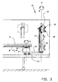
- Figure 3 shows the end of the transport device according to figure 2 at a larger scale.
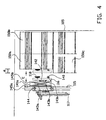
- Figure 4 shows a detail of an alternative embodiment of the end of a manipulator according to the invention, with which a load can be picked up.
- Figure 5 shows another exemplary embodiment of the device according to the invention in side view, in which only the end with the manipulator is shown.
- Figure 6 is a top view of figure 5.
- Figure 1 shows a first embodiment of the invention in top view. Shown is a telescopic conveyor 1 which consists of a fixedly positioned portion 1 a, in which a middle portion 1b and an end portion 1c can telescope.
- the telescopic conveyor 1 is positioned in a loading station 2 and connects to supply and discharge conveyors 3 and 4.
- the fixed portion 1a can be moveable to other loading doors of the loading station; when loading and unloading its position is fixed.
- the telescopic conveyor may consists of more or fewer parts.
- the telescopic conveyor can also be used without the supply and discharge conveyor. In figure 1 barrels 50 are transported, but instead of that other packed goods such as crates and boxes and the like can be transported.
- the telescopic conveyor 1 In the extended position drawn the telescopic conveyor 1 extends into a trailer 5 which with its rear end is placed against the loading station 2. Near the end 6 of the telescopic conveyor 1 extending in the trailer 5, a manipulator 10 is arranged, which will be described in more detail below. With the manipulator 10 the barrels 50 can be lifted from the end 6 of the telescopic conveyor 1 and placed in the trailer. Drawn is the position 10a in which the manipulator 10 is positioned such that it is able to lift two barrels 50 from the end 6, and the position 10b in which the manipulator 10 places the barrels in the trailer 5. Additionally the barrels 50 can be lifted from the trailer onto the conveyor 1 with the manipulator 10.
- Figure 2 shows the device according to figure 1 in side view. It can clearly be seen here that the manipulator 10 has a tool 16, on which suction cups 18 are arranged, in which the tool 16 can be brought into various positions with the help of manipulator 10, of which positions two are shown by dotted lines.
- the fixed portion 1a of the telescopic conveyor 1 is provided with hydraulic cylinders 7, with which the front, extendable end of the telescopic conveyor 1 can be placed somewhat upwardly inclined. This is done in order to prevent that the wheels of the manipulator 10 are impeded by the transition between the trailer 5 and the loading station, where a difference in level will usually be present and by the supply and discharge conveyor 4, or other irregularities.
- FIG. 3 shows the end portion 1c of the telescopic conveyor 1 with the end 6 and on it the manipulator 10 at a larger scale.
- the manipulator 10 consists of a trolley 11, which with the help of guidances 12 is moveable along guidance tracks 8 on either side of the end 6 of the end portion 1 c of the telescopic conveyor 1 in the directions C. Said guidance tracks 8 are arranged at the bottom side so that the supplied or discharged packed goods are not hindered by the manipulator 10.
- the trolley 11 of the manipulator 10 is provided with a swivel arm 13, which with the help of projecting wheels 14 is able to find support on the floor of the trailer 5.
- the swivel arm 13 can be swivelled in the directions D about the vertical central axis of the trolley 11, within boundaries determined by the wheels.
- the location of the swivel arm 13 is chosen as low as possible, so as to be able to bring the tool as low as possible for engaging the loads placed on the loading floor as well.
- the swivel arm 13 is provided with a vertical guidance 15, along which the tool 16, with a trolley which is not further shown, is moveable in the directions A, by means of for instance band cylinder 17.
- the vertical guidance 15 can be rotated in directions B about its own axis S.
- the operation of the device according to the invention is as follows.
- the loading door of the loading station is opened and the telescopic conveyor 1 is telescopingly introduced into the trailer 5, after which the manipulator 10 with its wheels 14 is placed on the floor of the trailer 5 by operation of the hydraulic cylinders 7.
- barrels 50 are supplied two by two, or one at a time, over the telescopic conveyor 1 to its end 6.
- the manipulator 10 is placed in position 10a, and the barrels 50 are engaged with the help of suction cups 18.
- the tool 16 is moved a little upwards along the vertical guidance 15 in order to lift the barrels 50, after which the entire manipulator 10 is moved forwards, while simultaneously the vertical guidance 15 is rotated about its axis in order to orient the barrels to the front.
- the swivel arm 13 can be swivelled in order to bring the barrels 50 near a side wall of the trailer 5, the vertical guidance 15 simultaneously rotating about its own axis in order to keep the barrels 50 in the correct position so that the manipulator 10 in its position 10b is able to put the barrels 50 in a corner of the trailer 5.
- the subsequent barrels can subsequently be placed two by two, or one at a time next to, on and in front of the barrels already placed there.
- a trailer 5 When unloading a trailer 5 with barrels, one or two barrels engaged which are still in a row of barrels, are often first swivelled a little in order to be able to easily take them out of the row, without scraping along the wall of the trailer 5.
- crates and the like can be placed in or unloaded from the container or trailer 5 with the help of the manipulator 10.
- the manipulator 10 is pneumatically driven. When the sizes and the stacking pattern of the packed goods are known, it is possible to automatically or semi-automatically load and unload by the manipulator 10. Both loading and unloading can be carried out automatically; deviations from the pattern or goods can be adjusted semi-automatically.
- the telescopic conveyor 1 is belt conveyor, of which the end 6 is designed as roller conveyor so to be able to offer better support when placing the packed good, such as the barrels, on the telescopic conveyor.
- manipulator 10 can be arranged at the end of other types of continuous conveyors, such as a conveyor of a fixed length which can be moved in its entirety.
- FIG 4 An alternative embodiment shown in figure 4 in which comparable parts have the same reference numbers increased by 100, is particularly advantageous because of the possibility of picking up barrels, boxes etcetera 150 when these are not placed straight on top of each other. Shown is that the barrel 150a is shifted over a distance d on the barrel 150c. When the manipulator is brought near the barrels, there is a chance that the end of the swivel arm (not shown) has been brought at a short distance from the barrel 150c, but that then the carrier 116' with the suction cup 118 cannot reach onto the wall of the barrel 150a, because the distance d is too large.
- this is solved by connecting the tool 116 in such a way to the trolley 144 with which the tool can be moved along the vertical guidances 115, that a movement in the direction E is possible.
- this is achieved by means of two plates 145a and 145d which are connected with the trolley 144 and the carrier 116', (the latter by means of vertical pivot pin connection 142), respectively.
- a linking construction is present between the plates 145a and 145b which are each fixedly connected with one end to a plate 145a and 145b concerned and with the other end can be slid along it in vertical direction, yet still durably connected.
- bellows 141a, 141b For the movement of the plates 145a, 145b with respect to each other use is made of bellows 141a, 141b, which can be pneumatically pressurized with suitable means that are not further shown in order to expand.
- a draw spring may be provided here which with the ends is attached to the plates 145a, 145b, 141b in order to automatically letting them move towards each other when the pressure in the bellows 141a, 141b decreases.
- the pivot pin connection 142 renders the levelling of the position of the carrier 116' possible, both about a vertical axis and (to some extent) about a horizontal axis -as a result of the rubber sleeve in it-.
- FIG. 5 shows the device in side view.
- the end portion 1c of the telescopic conveyor 1 can be seen, with at its bottom side on either side the guidance tracks 8.
- a trolley 21 is moveable, which rests on the floor of the trailer 5 with wheels 22.
- the trolley 21 does not extend beyond the end portion 1c of the telescopic conveyor 1.
- two lifting means having a horizontal support plate or support fork 29 and vertical plate 23 are attached to the trolley 21 on either side of the end portion 1 c, in which the parallel running rods 24, 25 are attached to the trolley 21 by means of hinge points 26, 27.
- the lowermost rods 25 are connected to a hydraulic cylinder 28, as a result of which the rods 25 on either side of the end portion 1c can simultaneously be rotated. Because of the rod structures 24, 25 the lifting means 23, 29 are simultaneously moved upwards or downwards, in which the lifting arms 29 remain horizontal.
- a cylinder 30 is attached to the plates 23, of which cylinder the plunger that is not further shown can extend through the plate 23 so that it can keep on pressing against the crate 51 with its end.
- the operation of the third exemplary embodiment is as follows.
- the arms 25 are swivelled such that the lifting means 23, 29 are brought entirely under the top surface of the end portion 1c.
- the crate 51 is now brought in a position as shown in figure 5 and 6 by the full lines.
- the lifting means 23, 29 are swivelled upwards with the help of the pneumatic cylinder 28, in which the lifting arms 29 lift the crate a little so that it comes free from the end portion 1c.
- the trolley 21 is moved forwards along the guidance tracks 8, so that the crate 51 is present beyond the end of the end portion 1c, after which it is placed on the floor of the trailer 5.
- the crate 51 When the crate 51 is not placed on a pallet, it is kept in its place with the horizontal plungers in cylinders 30, whereas the remainder of the manipulator 20 moves backwards.
- the crate 51 When the crate 51 has to be placed on a crate placed earlier on in the trailer 5, the crate 51 is lifted with the help of lifting means 23, 29 whereas the trolley 21 moves forward, in order to place it on the crate placed earlier on.
Landscapes
- Engineering & Computer Science (AREA)
- Aviation & Aerospace Engineering (AREA)
- Mechanical Engineering (AREA)
- Loading Or Unloading Of Vehicles (AREA)
Applications Claiming Priority (2)
| Application Number | Priority Date | Filing Date | Title |
|---|---|---|---|
| NL1011978 | 1999-05-06 | ||
| NL1011978A NL1011978C2 (nl) | 1999-05-06 | 1999-05-06 | Inrichting voor transport van stukgoed. |
Publications (2)
| Publication Number | Publication Date |
|---|---|
| EP1052205A1 EP1052205A1 (de) | 2000-11-15 |
| EP1052205A9 true EP1052205A9 (de) | 2001-05-16 |
Family
ID=19769137
Family Applications (1)
| Application Number | Title | Priority Date | Filing Date |
|---|---|---|---|
| EP00201638A Withdrawn EP1052205A1 (de) | 1999-05-06 | 2000-05-04 | Vorrichtung zum kontinuierlichen Fördern von verpackten Produkten |
Country Status (2)
| Country | Link |
|---|---|
| EP (1) | EP1052205A1 (de) |
| NL (1) | NL1011978C2 (de) |
Families Citing this family (12)
| Publication number | Priority date | Publication date | Assignee | Title |
|---|---|---|---|---|
| NL1017970C2 (nl) * | 2001-05-01 | 2002-11-05 | Chord Projects | Inrichting, samenstel en werkwijze voor het in- en uitladen van stukgoederen in een laadruimte. |
| EP2570372A1 (de) * | 2011-09-19 | 2013-03-20 | Greif International Holding BV. | Frachthandhabungssystem |
| EP3495293B1 (de) | 2013-05-17 | 2023-05-03 | Intelligrated Headquarters LLC | Robotischer kartonentlader |
| US10807805B2 (en) | 2013-05-17 | 2020-10-20 | Intelligrated Headquarters, Llc | Robotic carton unloader |
| US9487361B2 (en) | 2013-05-17 | 2016-11-08 | Intelligrated Headquarters Llc | Robotic carton unloader |
| US9650215B2 (en) | 2013-05-17 | 2017-05-16 | Intelligrated Headquarters Llc | Robotic carton unloader |
| US9493316B2 (en) | 2013-07-30 | 2016-11-15 | Intelligrated Headquarters Llc | Robotic carton unloader |
| WO2015031670A1 (en) | 2013-08-28 | 2015-03-05 | Intelligrated Headquarters Llc | Robotic carton unloader |
| US9623569B2 (en) | 2014-03-31 | 2017-04-18 | Intelligrated Headquarters, Llc | Autonomous truck loader and unloader |
| GB2571010B (en) | 2016-09-14 | 2022-02-02 | Intelligrated Headquarters Llc | Robotic carton unloader |
| US10597235B2 (en) | 2016-10-20 | 2020-03-24 | Intelligrated Headquarters, Llc | Carton unloader tool for jam recovery |
| CN112551200B (zh) * | 2020-12-14 | 2022-04-26 | 山东商业职业技术学院 | 一种冷链物流用卸货设备 |
Family Cites Families (4)
| Publication number | Priority date | Publication date | Assignee | Title |
|---|---|---|---|---|
| CH648806A5 (en) * | 1980-11-13 | 1985-04-15 | Ind Beratung Anstalt | Apparatus for loading uniformly packed goods, especially in containers of substantial length |
| US5174708A (en) * | 1988-12-06 | 1992-12-29 | Yellow Freight System, Inc. | Boom mounted multiple stage freight lift apparatus |
| US5015145A (en) * | 1989-10-06 | 1991-05-14 | R. J. Reynolds Tobacco Company | Automated cargo loading system |
| DE19719748C2 (de) * | 1997-05-09 | 2001-03-29 | Fraunhofer Ges Forschung | Vorrichtung zum Handhaben von Stückgütern, insbesondere von Paketen, für das Be- und Entladen eines Laderaumes sowie Verfahren zum Entladen eines Laderaumes |
-
1999
- 1999-05-06 NL NL1011978A patent/NL1011978C2/nl not_active IP Right Cessation
-
2000
- 2000-05-04 EP EP00201638A patent/EP1052205A1/de not_active Withdrawn
Also Published As
| Publication number | Publication date |
|---|---|
| NL1011978C2 (nl) | 2000-11-07 |
| EP1052205A1 (de) | 2000-11-15 |
Similar Documents
| Publication | Publication Date | Title |
|---|---|---|
| KR102342280B1 (ko) | 물체 핸들링 시스템 및 방법 | |
| US9725257B2 (en) | Device for handling stackable cargo units in a cargo space, as well as a method for handling stackable cargo units | |
| CN107878989B (zh) | 一种仓储自动取料机 | |
| US5833198A (en) | Mechanically operated lift table | |
| US9950881B2 (en) | Robotic trailer loading device with telescoping robot | |
| EP1052205A9 (de) | Vorrichtung zum kontinuierlichen Fördern von verpackten Produkten | |
| US11117741B2 (en) | Object handling device and method | |
| US11884314B2 (en) | Laterally operating payload handling device | |
| JP2009539732A (ja) | 延長フォークを有するパレット台車 | |
| CN218289121U (zh) | 搬运拣选小车及仓储系统 | |
| US20120255835A1 (en) | Cargo handling system | |
| US20130195592A1 (en) | Push-Pull Device, Fork-Lift Truck and Method for Displacing Goods | |
| CN116788872B (zh) | 一种适用于火车货运袋装物料的全自动装卸机 | |
| US4268210A (en) | Pallet unloader for fork lifts | |
| US10850657B2 (en) | Dumpster handling device and method | |
| US20230192425A1 (en) | Apparatus and method for unloading and loading a transport unit | |
| CN114435976B (zh) | 一种集装箱自动装箱系统及方法 | |
| CN212449766U (zh) | 一种输送设备 | |
| US12122613B2 (en) | Device and process for automated loading and unloading of parcels | |
| US20100003116A1 (en) | Transport vehicle for raising and transporting ULDs and cargo pallets | |
| CA2093892C (en) | High efficiency material handling and transportation system | |
| CA2291924A1 (en) | Telescoping flat bed gripping and lift assembly | |
| CN217050085U (zh) | 货物装卸装置、货物输送设备和仓储系统 | |
| JPH0692470A (ja) | トラックローダ | |
| JP3223068B2 (ja) | 荷物受け渡し装置および荷物積み降ろし装置 |
Legal Events
| Date | Code | Title | Description |
|---|---|---|---|
| PUAI | Public reference made under article 153(3) epc to a published international application that has entered the european phase |
Free format text: ORIGINAL CODE: 0009012 |
|
| AK | Designated contracting states |
Kind code of ref document: A1 Designated state(s): AT BE CH CY DE DK ES FI FR GB GR IE IT LI LU MC NL PT SE |
|
| AX | Request for extension of the european patent |
Free format text: AL;LT;LV;MK;RO;SI |
|
| 17P | Request for examination filed |
Effective date: 20010418 |
|
| AKX | Designation fees paid |
Free format text: AT BE CH CY DE DK ES FI FR GB GR IE IT LI LU MC NL PT SE |
|
| 17Q | First examination report despatched |
Effective date: 20020813 |
|
| GRAP | Despatch of communication of intention to grant a patent |
Free format text: ORIGINAL CODE: EPIDOSNIGR1 |
|
| STAA | Information on the status of an ep patent application or granted ep patent |
Free format text: STATUS: THE APPLICATION IS DEEMED TO BE WITHDRAWN |
|
| 18D | Application deemed to be withdrawn |
Effective date: 20040727 |