EP1052322A2 - Antriebsvorrichtung für einen oszillierenden Greifer einer Nähmaschine - Google Patents
Antriebsvorrichtung für einen oszillierenden Greifer einer Nähmaschine Download PDFInfo
- Publication number
- EP1052322A2 EP1052322A2 EP00810086A EP00810086A EP1052322A2 EP 1052322 A2 EP1052322 A2 EP 1052322A2 EP 00810086 A EP00810086 A EP 00810086A EP 00810086 A EP00810086 A EP 00810086A EP 1052322 A2 EP1052322 A2 EP 1052322A2
- Authority
- EP
- European Patent Office
- Prior art keywords
- drive device
- pinion
- drive
- rack
- gripper
- Prior art date
- Legal status (The legal status is an assumption and is not a legal conclusion. Google has not performed a legal analysis and makes no representation as to the accuracy of the status listed.)
- Granted
Links
Images


Classifications
-
- D—TEXTILES; PAPER
- D05—SEWING; EMBROIDERING; TUFTING
- D05B—SEWING
- D05B57/00—Loop takers, e.g. loopers
- D05B57/30—Driving-gear for loop takers
Definitions
- the invention relates to a drive device for an oscillating hook of a sewing machine Preamble of claim 1.
- the rack is in the Swiss patent specification 241880 in a longitudinal guide tangential to the gear and is from a crank rod attached to a crank driven.
- the teeth of the rack are directly on one Extension of the crank rod is formed. The latter will from a rocker arm to an oscillating motion transferred.
- Both drive devices can both horizontally and vertically oscillating grippers be used.
- Deflection of the needle is due to the deviation of the phase position between the eye of the needle and gripper tip influenced or limited.
- the Effects of this phase shift are described in the manual by Renters "The Sewing Machine Expert", Volume 3, 1957, described and illustrated.
- the conditions of the loop takeover when zigzag sewing is therefore waived. To sum up clearly that by little or ideally none at all Deviations from the conditions, such as when sewing there is a straight seam, a larger zigzag width would be achievable.
- the eccentric arrangement of the Drive gear on the gripper driver shaft, the Speed of the gripper tip when capturing the of the needle thread presented to the needle increase.
- the angular position of the largest eccentricity of the Gear with respect to the gripper tip will be like this chosen that the gripper tip in Loop detection area or time with the maximum speed is moved past the needle.
- the one sitting eccentrically on the gripper driver shaft Sprockets can be manufactured inexpensively.
- the rack on the gear can be coaxial to the eccentrically arranged gear a guide disc are provided, which by an adjacent Guide means the lifting of the rack from the teeth prevented.
- a crank rod is formed by spring force in Engage with the teeth of the gear can be kept.
- the Invention can be arranged by arranging the teeth of the rack on a curved line the speed curve of the Gripper tip continues to grip the thread loop be optimized.
- Advantageous in terms of noise turns out to be the use of a timing belt as an exaggeration.
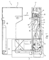
- a sewing machine 1 is shown schematically in FIG Side view shown and it's in there Machine housing 3, to which the free arm 5 and above the head 7 with the presser foot and not shown Needle bar holders are attached, visible.
- the laterally cut free arm 5 is open the left side a crank drive 11 with one on it articulated crank rod 13 and at its front end a rack 15 visible.
- the rack 15 meshes with a gear or pinion 17, which is eccentric the drive shaft 19 for the gripper 21 is placed.
- the needle plate 23 is visible above the gripper 21 whose tap hole 25, the needle 9 can be passed.
- the Crank drive 11 is by a not shown Motor started to rotate.
- the crank drive is synchronous with the drive for the needle bar, not shown, and whose attached needle 9 is formed.
- Figure 1 is the crank drive 13 with it attached rack 15 in the rear position and the needle 9 is not in engagement with the sewing material (sewing material not shown).
- Figure 2 the needle 9 is through Stitch hole 25 immersed in the throat plate 23 and the Rack 15 has its extreme front and reverse position reached. In the front extreme position are those Teeth of the pinion 17 with the teeth of the rack 15 engaged, which is the smallest distance to the axis A of the Have drive shaft 19.
- the teeth 27 of the rack 15 within one loop-shaped recess 29 at the end of the crank rod 13.
- the area of the teeth 27 opposite Crank rod end faces one essentially parallel the slit-shaped opening 31 running through the tooth back.
- a sliding block designed to move longitudinally 33 used and is from a hold-down 35 to the lower boundary surface 37 of the slit-shaped opening 31 pressed.
- the hold-down 35 preferably comprises two parallel leg, the side of the slit-shaped opening 31 come to rest and this cover on the side.
- the hold-down 35 is at one end a pivot axis 39 and is articulated by a spring 41 pressed clockwise on the sliding block 33.
- the Force of the spring 41 is such that it is sufficient, the teeth 27 of the rack 15 safely at all times to keep in engagement with the teeth of the pinion 17.
- the periphery 47 as Guide surface acts.
- Disk 45 is preferably 45 made in one piece with the pinion 17 and sits with same eccentricity on the drive shaft 19 of the Grab driver 22. This ensures that the distance of the tooth flanks, which engage with the rack 15 and the line of contact between the periphery 47 the disc 45 with the guide surface 43 at the end 14 of the Crank rod 13 always remains constant.
- crank rod 13 with the rack 15 is preferred produced as a fine-cut stamped part and can therefore be very precise and also extremely inexpensive to manufacture.
- the position of the rack is a toothed belt 61, which on the one hand the eccentrically mounted pinion 17 and on the other hand, one rotatably mounted on an axis 75
- Output gear 63 wraps around the crank rod 13 is driven to oscillate.
- One by a spring 69 loaded belt tensioning lever 65 with a tensioning pulley 67 resembles that due to the eccentricity of the pinion 17 caused changes in the loop length of the Timing belt 61 out.
- the changes in Wrapping lengths are very small because of that too Eccentricity of the pinion 17 is extremely low.
- the gear 63 can also be used be mounted eccentrically on an axis 77.
- the gear 63 could also be segment-like Belt carriers are used because the toothed belt 61 only a very limited oscillating stroke anyway executes.
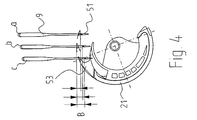
- FIG 4 the location of the Needle 9 in the three possible puncture positions of the gripper 21 or the gripper tip 53 is shown.
- Position a is the position of the needle 9 and the hook 21 can be seen at the "right" puncture.
- the position b shows the position of the gripper 21 and needle 9 at Center stitch, as used for straight seams, and in position c the needle 9 and the gripper 21 are in the puncture position "left” can be seen.
- This Illustration shows that the distance B between the needle eye 51 and the hook tip 53 in dependence is different in size from the lateral position of the needle 9 (different phase position).
Landscapes
- Engineering & Computer Science (AREA)
- Textile Engineering (AREA)
- Sewing Machines And Sewing (AREA)
- Devices For Conveying Motion By Means Of Endless Flexible Members (AREA)
Abstract
Description
- Figur 1
- eine Seitenansicht einer Freiarm-Nähmaschine, mit längs aufgeschnittenem Freiarm (hintere Extremlage der Zahnstange),
- Figur 2
- eine perspektivische Darstellung des Freiarms (Gehäuse weggelassen); Zahnstange in vorderer Extremstellung,
- Figur 3
- eine perspektivische Darstellung eines weiteren Greiferantriebs mit offener Gabel und einer Zahnstangenführung an einer exzentrisch gelagerten Scheibe,
- Figur 4
- eine schematische Seitenansicht des Greifers mit drei Nadelstellungen beim Einstich,
- Figur 5
- eine Seitenansicht weiteren Ausgestaltung einer Freiarm-Nähmaschine, mit längs aufgeschnittenem Freiarm.
Claims (12)
- Antriebsvorrichtung für einen oszillierenden Greifer (21) einer Nähmaschine (1), umfassend ein auf der Antriebswelle (19) für den Greifer (21) angeordnetes Zahnritzel (17) und eine von einem oszillierenden Kurbelantrieb (13) hin- und herführbares gezahntes Übertriebsmittel, dessen Zähne (27) mit dem Zahnritzel (17) im Eingriff stehen, dadurch gekennzeichnet, dass das Zahnritzel (17) exzentrisch auf der Antriebswelle (19) für den Greifer (21) aufgesetzt ist.
- Antriebsvorrichtung nach Anspruch 1, dadurch gekennzeichnet, dass als Übertriebsmittel eine Zahnstange (15) oder ein Zahnriemen (61) zwischen dem Kurbelantrieb (13) und dem Zahnritzel (17) eingesetzt ist.
- Antriebsvorrichtung nach Anspruch 2, dadurch gekennzeichnet, dass der Zahnstange (15) eine Führungsfläche (43) zugeordnet und dazu ausgebildet und bestimmt ist, die Zahnstange (15) im Eingriff mit dem Zahnritzel (17) zu halten.
- Antriebsvorrichtung nach Anspruch 3, dadurch gekennzeichnet, dass die Führungsfläche (43) innerhalb einer unterhalb der Zahnstange (13) angeordneten, stirnseitig offenen oder einer geschlossenen schlitzförmigen Öffnung (31) am Ende der Kurbelstange (13) ausgebildet ist.
- Antriebsvorrichtung nach einem der Ansprüche 3 oder 4, dadurch gekennzeichnet, dass die Führungsfläche (43) gleitend an einer koaxial zum Zahnritzel (17) auf der Antriebswelle (19) aufgesetzten Führungsscheibe (45) anliegt.
- Antriebsvorrichtung nach Anspruch 5, dadurch gekennzeichnet, dass die Führungsscheibe (45) als stirnseitige axiale Verlängerung des Zahnritzels (17) ausgebildet oder als separates Teil auf der Antriebswelle (19) aufgesetzt ist.
- Antriebsvorrichtung nach einem der Ansprüche 1 oder 2, dadurch gekennzeichnet, dass an einer Führungskante (37) an der Kurbelstange (13) ein federbelasteter Gleitschuh (33) längsverschiebbar gehalten ist.
- Antriebsvorrichtung nach Anspruch 7, dadurch gekennzeichnet, dass die Führungskante (37) im wesentlichen parallel zu den Zähnen der Zahnstange (15) verläuft und Teil der Kurbelstange (13) ist.
- Antriebsvorrichtung nach einem der Ansprüche 7 oder 8, dadurch gekennzeichnet, dass der Gleitschuh (33) von einem federbelasteten Hebel (35) auf die Führungskante (37) niederdrückbar ist.
- Antriebsvorrichtung nach Anspruch 1, dadurch gekennzeichnet, dass als Übertriebsmittel ein Zahnriemen (61) eingesetzt ist, welcher einerseits das Zahnritzel (17) und anderseits einen Riementräger oder ein Zahnrad (63) umschlingt, welcher Riementräger oder welches Zahnrad (63) durch den Kurbelantrieb (13) oszillierend antreibbar ist.
- Antriebsvorrichtung nach Anspruch 10, dadurch gekennzeichnet, dass der Zahnriemen (61) mit einem federbelasteten Spannhebel (65) und einer daran befestigten Spannrolle (67) gespannt gehalten wird.
- Antriebsvorrichtung nach einem der Ansprüche 10 oder 11, dadurch gekennzeichnet, dass das Antriebszahnrad (63) exzentrisch auf der Achse (77) gelagert ist.
Applications Claiming Priority (4)
| Application Number | Priority Date | Filing Date | Title |
|---|---|---|---|
| CH85999 | 1999-05-07 | ||
| CH85999 | 1999-05-07 | ||
| CH227299 | 1999-12-10 | ||
| CH227299 | 1999-12-10 |
Publications (3)
| Publication Number | Publication Date |
|---|---|
| EP1052322A2 true EP1052322A2 (de) | 2000-11-15 |
| EP1052322A3 EP1052322A3 (de) | 2001-10-04 |
| EP1052322B1 EP1052322B1 (de) | 2003-05-28 |
Family
ID=25685917
Family Applications (1)
| Application Number | Title | Priority Date | Filing Date |
|---|---|---|---|
| EP00810086A Expired - Lifetime EP1052322B1 (de) | 1999-05-07 | 2000-01-31 | Antriebsvorrichtung für einen oszillierenden Greifer einer Nähmaschine |
Country Status (6)
| Country | Link |
|---|---|
| US (1) | US6182589B1 (de) |
| EP (1) | EP1052322B1 (de) |
| JP (1) | JP4381561B2 (de) |
| CN (1) | CN1096518C (de) |
| DE (1) | DE50002325D1 (de) |
| TW (1) | TW573694U (de) |
Families Citing this family (2)
| Publication number | Priority date | Publication date | Assignee | Title |
|---|---|---|---|---|
| US6269760B1 (en) * | 1999-10-08 | 2001-08-07 | Robert A. Moore | Wide needle swing oscillating hook system for sewing machines |
| CN105624928B (zh) * | 2016-03-30 | 2019-05-21 | 王雪松 | 便携式缝纫机 |
Family Cites Families (7)
| Publication number | Priority date | Publication date | Assignee | Title |
|---|---|---|---|---|
| US1613605A (en) * | 1924-03-26 | 1927-01-11 | Singer Mfg Co | Looper mechanism for sewing machines |
| US2325467A (en) * | 1940-05-24 | 1943-07-27 | Beyer Werner Kurt Rudolf | Sewing machine |
| US3029762A (en) * | 1960-09-23 | 1962-04-17 | Singer Mfg Co | Shuttle mechanism for sewing machines |
| US3954070A (en) * | 1975-05-28 | 1976-05-04 | The Singer Company | Adjustable loop taker support for sewing machines |
| DE2938802A1 (de) * | 1979-09-25 | 1981-04-02 | The Singer Co., 06904 Stamford, Conn. | Naehmaschine |
| US5396853A (en) * | 1994-03-04 | 1995-03-14 | Huang; Dennis | Double-thread hand sewing machine transmission mechanism |
| US6032597A (en) * | 1997-09-30 | 2000-03-07 | Brother Kogyo Kabushiki Kaisha | Shuttle hook driver for sewing machine |
-
2000
- 2000-01-31 DE DE50002325T patent/DE50002325D1/de not_active Expired - Lifetime
- 2000-01-31 EP EP00810086A patent/EP1052322B1/de not_active Expired - Lifetime
- 2000-03-15 TW TW92214580U patent/TW573694U/zh not_active IP Right Cessation
- 2000-04-03 US US09/541,181 patent/US6182589B1/en not_active Expired - Fee Related
- 2000-04-30 CN CN00108241A patent/CN1096518C/zh not_active Expired - Fee Related
- 2000-05-01 JP JP2000132332A patent/JP4381561B2/ja not_active Expired - Lifetime
Also Published As
| Publication number | Publication date |
|---|---|
| US6182589B1 (en) | 2001-02-06 |
| JP2000342875A (ja) | 2000-12-12 |
| CN1273296A (zh) | 2000-11-15 |
| EP1052322A3 (de) | 2001-10-04 |
| CN1096518C (zh) | 2002-12-18 |
| DE50002325D1 (de) | 2003-07-03 |
| EP1052322B1 (de) | 2003-05-28 |
| TW573694U (en) | 2004-01-21 |
| JP4381561B2 (ja) | 2009-12-09 |
Similar Documents
| Publication | Publication Date | Title |
|---|---|---|
| DE3018892C2 (de) | Nähmaschine für chirurgische Eingriffe | |
| DE102007031072B4 (de) | Nähmaschine | |
| DE3348223C2 (de) | ||
| DE2338473C2 (de) | Fadenabschneider für eine Doppelsteppstichnähmaschine | |
| DE2718607C2 (de) | Nähmaschine mit einer angetriebenen Vorschubrolle | |
| DE2156316C3 (de) | Doppelkettenstich-Zickzacknähmaschine | |
| DE1941681A1 (de) | Fadenschneideinrichtung an Doppelsteppstichnaehmaschinen | |
| DE3114409A1 (de) | Zickzack-naehmaschine | |
| EP0453543A1 (de) | Automatisches strumpfwendegerät für eine kettelmaschine. | |
| EP1052322B1 (de) | Antriebsvorrichtung für einen oszillierenden Greifer einer Nähmaschine | |
| CH643892A5 (de) | Antriebsvorrichtung fuer das antriebszahnrad des traegerbandes fuer den schussfadengreifer einer schuetzenlosen webmaschine. | |
| DE4219921C2 (de) | Mehrnadel-Nähmaschine mit Einfädelvorrichtung zum Einfädeln einer Mehrzahl von Nadeln | |
| DE2026523B2 (de) | Steuervorrichtung an einer Webmaschine zum Antreiben einer Kantennadel | |
| DE10127591C1 (de) | Verfahren und Vorrichtung zum Bilden einer Endverknotung einer Einfaden-Kettenstichnaht | |
| DE3225046C2 (de) | Nähautomat mit einem Nähkopf und einer kontinuierlichen Werkstück-Vorschubvorrichtung | |
| DE2157100C3 (de) | Maschine zum Zusammennähen von Netzbahnen | |
| AT507786B1 (de) | Kettenstich-nähmaschine | |
| DE391522C (de) | Naehmaschine mit einer in dem Stoff und mit Bezug auf letzteren seitlich bewegten Nadel | |
| DE2650352C2 (de) | Nähmaschine mit einem oberhalb der Stichbildestelle angeordneten Greifer | |
| DE4007994C2 (de) | Blindstich-Nähmaschine | |
| DE1941681C (de) | Doppelsteppstichnähmaschine mit einer Fadenschneideinrichtung | |
| DE2500461C3 (de) | Nähmaschine zum Einfassen der Kanten von Bodenbelägen o.dgl | |
| DE428466C (de) | Vorschubvorrichtung an Naehmaschinen | |
| DE3839662A1 (de) | Naehmaschine mit einer hin- und herbewegbaren, fadenfuehrenden nadel | |
| DE620723C (de) | Maschine zur Herstellung eines aus nebeneinanderliegenden und in Querrichtung miteinander vernaehten Faeden bestehenden Gewebes |
Legal Events
| Date | Code | Title | Description |
|---|---|---|---|
| PUAI | Public reference made under article 153(3) epc to a published international application that has entered the european phase |
Free format text: ORIGINAL CODE: 0009012 |
|
| AK | Designated contracting states |
Kind code of ref document: A2 Designated state(s): AT BE CH CY DE DK ES FI FR GB GR IE IT LI LU MC NL PT SE Kind code of ref document: A2 Designated state(s): CH DE IT LI SE |
|
| AX | Request for extension of the european patent |
Free format text: AL;LT;LV;MK;RO;SI |
|
| RIN1 | Information on inventor provided before grant (corrected) |
Inventor name: STUCKI, ANDRE Inventor name: ANDEREGG, CHRISTIAN |
|
| PUAL | Search report despatched |
Free format text: ORIGINAL CODE: 0009013 |
|
| AK | Designated contracting states |
Kind code of ref document: A3 Designated state(s): AT BE CH CY DE DK ES FI FR GB GR IE IT LI LU MC NL PT SE |
|
| AX | Request for extension of the european patent |
Free format text: AL;LT;LV;MK;RO;SI |
|
| RIC1 | Information provided on ipc code assigned before grant |
Free format text: 7D 05B 57/30 A, 7D 05B 3/02 B |
|
| 17P | Request for examination filed |
Effective date: 20011016 |
|
| AKX | Designation fees paid |
Free format text: CH DE IT LI SE |
|
| GRAH | Despatch of communication of intention to grant a patent |
Free format text: ORIGINAL CODE: EPIDOS IGRA |
|
| GRAH | Despatch of communication of intention to grant a patent |
Free format text: ORIGINAL CODE: EPIDOS IGRA |
|
| GRAA | (expected) grant |
Free format text: ORIGINAL CODE: 0009210 |
|
| AK | Designated contracting states |
Designated state(s): CH DE IT LI SE |
|
| REG | Reference to a national code |
Ref country code: CH Ref legal event code: NV Representative=s name: GEORG FISCHER AG PATENTABTEILUNG MFB 2645 Ref country code: CH Ref legal event code: EP |
|
| REF | Corresponds to: |
Ref document number: 50002325 Country of ref document: DE Date of ref document: 20030703 Kind code of ref document: P |
|
| REG | Reference to a national code |
Ref country code: SE Ref legal event code: TRGR |
|
| PLBE | No opposition filed within time limit |
Free format text: ORIGINAL CODE: 0009261 |
|
| STAA | Information on the status of an ep patent application or granted ep patent |
Free format text: STATUS: NO OPPOSITION FILED WITHIN TIME LIMIT |
|
| 26N | No opposition filed |
Effective date: 20040302 |
|
| REG | Reference to a national code |
Ref country code: CH Ref legal event code: PFA Owner name: BERNINA INTERNATIONAL AG Free format text: FRITZ GEGAUF AG BERNINA-NAEHMASCHINENFABRIK#SEESTRASSE#CH-8266 STECKBORN (CH) -TRANSFER TO- BERNINA INTERNATIONAL AG#SEESTRASSE 161#8266 STECKBORN (CH) |
|
| PGFP | Annual fee paid to national office [announced via postgrant information from national office to epo] |
Ref country code: CH Payment date: 20100122 Year of fee payment: 11 |
|
| PGFP | Annual fee paid to national office [announced via postgrant information from national office to epo] |
Ref country code: IT Payment date: 20100127 Year of fee payment: 11 |
|
| PGFP | Annual fee paid to national office [announced via postgrant information from national office to epo] |
Ref country code: DE Payment date: 20100122 Year of fee payment: 11 |
|
| PGFP | Annual fee paid to national office [announced via postgrant information from national office to epo] |
Ref country code: SE Payment date: 20100126 Year of fee payment: 11 |
|
| REG | Reference to a national code |
Ref country code: CH Ref legal event code: PL |
|
| REG | Reference to a national code |
Ref country code: SE Ref legal event code: EUG |
|
| PG25 | Lapsed in a contracting state [announced via postgrant information from national office to epo] |
Ref country code: CH Free format text: LAPSE BECAUSE OF NON-PAYMENT OF DUE FEES Effective date: 20110131 Ref country code: LI Free format text: LAPSE BECAUSE OF NON-PAYMENT OF DUE FEES Effective date: 20110131 |
|
| REG | Reference to a national code |
Ref country code: DE Ref legal event code: R119 Ref document number: 50002325 Country of ref document: DE Effective date: 20110802 |
|
| PG25 | Lapsed in a contracting state [announced via postgrant information from national office to epo] |
Ref country code: IT Free format text: LAPSE BECAUSE OF NON-PAYMENT OF DUE FEES Effective date: 20110131 |
|
| PG25 | Lapsed in a contracting state [announced via postgrant information from national office to epo] |
Ref country code: SE Free format text: LAPSE BECAUSE OF NON-PAYMENT OF DUE FEES Effective date: 20110201 |
|
| PG25 | Lapsed in a contracting state [announced via postgrant information from national office to epo] |
Ref country code: DE Free format text: LAPSE BECAUSE OF NON-PAYMENT OF DUE FEES Effective date: 20110802 |