EP1052323B1 - Aiguille de machine à coudre à chas mince - Google Patents
Aiguille de machine à coudre à chas mince Download PDFInfo
- Publication number
- EP1052323B1 EP1052323B1 EP00106097A EP00106097A EP1052323B1 EP 1052323 B1 EP1052323 B1 EP 1052323B1 EP 00106097 A EP00106097 A EP 00106097A EP 00106097 A EP00106097 A EP 00106097A EP 1052323 B1 EP1052323 B1 EP 1052323B1
- Authority
- EP
- European Patent Office
- Prior art keywords
- eye
- sewing machine
- machine needle
- central axis
- needle according
- Prior art date
- Legal status (The legal status is an assumption and is not a legal conclusion. Google has not performed a legal analysis and makes no representation as to the accuracy of the status listed.)
- Expired - Lifetime
Links
Images


Classifications
-
- D—TEXTILES; PAPER
- D05—SEWING; EMBROIDERING; TUFTING
- D05B—SEWING
- D05B85/00—Needles
Definitions
- the invention relates to a sewing machine needle, in particular for high-speed sewing machines with high Number of stitches.
- the sewing machine needle sticks through the material, creating a tap hole.
- the one to open the taphole The time available is the duration from the first Touch of the sewing material through the needle tip up to the eye passage.
- This taphole opening time is on one Lockstitch machine at 5000 stitches / min approx. 0.5 ms.
- the opening the taphole goes with a quick, almost explosive lateral displacement of the material. This leads to high frictional forces and thus high required ones Puncture forces as well as a high one, for sewing required, power requirement.
- the sewing material can be mechanical and also be thermally damaged. It is possible that Fibers or fiber associations (yarns) at the taphole opening be blown up. In addition, the high frictional forces cause a temperature rise on the needle that is inside the melting range of conventional synthetic fibers in just a few seconds reached. Such fibers are then or in the puncture area melted. Another consequence are common ones Nähzwirnbrüche.
- the sewing machine needles are subject in particular relatively high at high machine speeds mechanical loads. Increasing machine speeds cause increasing dynamic problems. In masses rotating on the sewing machine can cause vibrations, which particularly relate to the one-sided Impact sewing machine needles. These must also external forces, such as thread tension, deflections when Impact on the sewing material as well as operational influences, grown his. Are therefore used to increase stability Thicker needles are used, but the ones above will tighten problems mentioned.
- a sewing machine needle is included laterally bent shaft known.
- a thread groove that leads to an eye that is located near the tip of the sewing machine needle.
- the thread gutter is delimited by two side walls, which are extend into the eye area. In the transition from the over the thread groove leading to the side of the shaft the needle contour follows up to the needle tip Essentially a straight line.
- This document also discloses a sewing machine needle with cranked shaft. An end to the bend immediately follows the eye. In this area the eye walls are slightly behind on an opening side of the eye arched inside. However, the thickness of the needle also increases this embodiment from the top to beyond the eye always closed.
- the sewing machine needle according to the invention has a reduced one Cross-sectional ear volume with constant eye width and at the same time improved thread protection features on. This must give a stitch hole for a sewing thread Strength can be opened less wide, so that friction effects the sewing machine needle and the material to be sewn.
- the Cross-sectional reduction of the eye is due to a channel-side Indentation reached. The eye width is thereby not negatively affected, making sewing threads more conventional or given strength can be used.
- the indentation changes the characteristic of the puncture force curve.
- the first peak of power that comes through the eye passage a normal needle is usually dominant significantly reduced.
- the maximum tap hole expansion takes place comparatively gentle only when the upper one penetrates Needle shaft, i.e. if the lowering movement of the needle is slower and goes to zero.
- the explosive effect at the normal needle due to the maximum tap hole expansion highest penetration speed occurs is minimized or prevented.
- the indentation is preferably dimensioned such that the Eye walls have a total height at at least one point, which is slightly less than the height of one between the Tip and eye area. This makes it possible the widening from the top to the eye the sewing machine needle by a simultaneous slight Flattening a little bit and therefore only one overall to achieve slow increase in needle cross-section. This reinforces the advantages mentioned above.
- the sewing machine needle at least in a certain Area of the eye a substantially constant total height on, which also delays the opening movement when Grooving helps.
- the indentation of the sewing machine needle points at one advantageous embodiment an essentially constant Radius, with the center of curvature approximately at height the eye can be arranged.
- the radius is preferred dimensioned relatively large and is advantageous Fall about 3 to 4 times the nominal needle size. This is to be determined in an un weakened shaft area.
- the wall thickness within an eye wall can vary from one Vary side of the eye to the other.
- the side faces the sewing machine needle can be parallel to the central axis and in the transverse direction an acute angle be arranged including each other.
- a particularly advantageous embodiment of the invention Sewing machine needle has a thread groove, which extends with undiminished height into the eye area, however, the height of the thread gutter limiting Walls along the entire gutter, especially up to to the eye and to the bulge formed in the eye area, is constant. This enables maximum thread protection with a very lean training of the ⁇ hrs and thus low puncture forces and slow tap hole expansion.
- the shaft of the sewing machine needle is preferably with provided a lateral bend, that on the thread groove side of the sewing machine needle a groove sets.
- the fillet creates space for a thread gripper, which comes into contact with the sewing thread during seam formation.
- the height is walls bounding the thread groove in the transition to the eye slightly enlarged, which can improve the thread protection even more.
- the rounded trained and arranged offset against the central axis are.
- the curvature of the eye bridges is dimensioned so that the ends of the eye bridges are semicircular.
- the rounding axes the eye bridges against each other by about half the eye height added.
- the arrangement is preferably such that a tangent running through the eye with the Central axis encloses an angle, which is preferably clear is less than 20 °.
- a stretched through the eye Thread with a thickness that corresponds to the strength of the used Sewing thread corresponds to, closes with the central axis preferably also an angle that is smaller than 20 °.
- a sewing machine needle 1 is cut out in FIG illustrated. It has a shaft 2 which in Figure 1 to the right in a tip 3.
- the shaft 2 defines a central axis 4, which runs through the tip 3.
- the shaft 2 does not extend further from one shown clamping part away, in a corresponding Attachment of a sewing machine.
- the sewing machine needle 1 shows in Figure 1 on the left their shaft 2 one rounded on its upper side 5 and on their side surfaces 6, 7 flat cross section.
- the sewing machine needle 1 is on its lower side 8 a thread groove 9 provided by two side walls 10, 11 is limited.
- the side walls 10, 11 are polygonal limited or rounded to a channel bottom 12 over.
- the thread channel extends 9 along the shaft 2 over an offset area 14 in which the shaft 2 is cranked, i.e. is bent out laterally.
- the offset area 14 lies on the Upper side 5 of the sewing machine needle 1 has a fillet 15 firmly.
- the back or saddle of the fillet 15 comes up at a short distance from the central axis 4.
- the Cross section of the sewing machine needle 1 results in this Area from Figure 3.
- the sewing machine needle 1 in the offset area 14 compared to that in FIG 2 illustrated area widened, but somewhat flatter educated.
- the cross sections of the shaft 2 in the Cross sections according to Figure 2 and Figure 3 are correct in area roughly match. They are about 12% smaller than that nominal cross-sectional area.
- a transition area adjoins the offset area 14 17, in which the center of the cross section from a shifted position again close the central axis 4 or shifted to the same.
- the thread gutter 9 extends through the offset area and the Transition area 17 to an eye 18, which, as from Figure 1, located near the tip 3 is.
- the eye leads through the sewing machine needle in one direction 1, with the offset direction in the offset area 14 matches.
- Cross section reveals the eye 18 of two eye walls 19, 20 delimited, between which a passage is trained.
- the eye walls 19, 20 are on their opposite inner surfaces 21, 22 essentially flat or slightly arched.
- the two inner surfaces 21, 22 are aligned approximately parallel to one another, while the outer sides 6, 7 here an acute angle include with each other.
- the eye walls 19, 20 point thereby a slightly larger on the thread channel 9 side Wall thickness than on that lying away from the thread groove 9 Page.
- the total cross section is up to 10% against the nominal needle size of the sewing machine needle in question 1 decreased.
- an eye bridge 23 is formed, the end 24 of the eye 18 in the axial direction (direction the central axis 4) limited.
- the end 24 is with maximum possible radius rounded without edges.
- the gutter floor 12 of the thread runner 9 thus extends without edges to the end 24 of the ⁇ hrstegs 23.
- the side walls 10, 11 of the thread groove 9 go from a first, in the Offset area 14, height H to be measured slightly increased height H1 above that in a parallel area 25 can be seen in which the thread groove 9 obliquely runs to the central axis 4.
- Eye walls 19, 20, as illustrated in Figure 1 with a Provide indentation 26 through which the lower, in Figure 1, Inlet of the eye 18 lying on the side of the thread groove 9 is offset towards the central axis 4.
- a conical region 27 which is up to the top 3 leads.
- the largest to be measured at around 28 Radius of the conical region 27 is larger than that Distance of the inlet of the eye 18 in the region of the indentation 26 to the central axis 4.
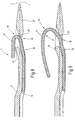
- the Indentation 26, as illustrated in FIG. 1 through a radius R starting from a center of curvature M set on the side of the thread groove 9 in Extension of the eye 18 can be found.
- the radius R is about four times the nominal needle size Nm.
- the eyelet at its end 30th is rounded.
- the ⁇ hrsteg 29 runs on the of the indentation 26 remote side in a concave base 31 out.
- the sewing machine needle is for illustration 1 in Figure 5 cut along the section line V-V shown.
- the cross section is approximately round.
- the cross section is here against the cross-section that corresponds to the nominal needle size, reduced by about 20%.
- the sewing machine needle 1 described so far works as follows:
- FIG. 6 shows the sewing machine needle 1 with a sewing thread 32 illustrates that led through the eye 18 is. It lies in the thread groove 9 and bends from it stretched through the eye 18. In the area of the concave bottom surface 31 it is hollow.
- the sewing machine needle 1 has not yet inserted into the material. It starts now move towards the sewing material and plunge into it. First, the tip 3 penetrates the material, after which by continued axial movement of the sewing machine needle 1 along its central axis 4 the conical area 27 enters the material and the stitch hole up to the eye 18 expands. The expansion takes place gradually and relatively evenly to a measure so that the sewing thread 32 can be pulled through the tap hole, making it around the ⁇ hrsteg 23. This is illustrated in Figure 7.
- the sewing material glides over the Eye 18, passing through due to the height of the thread groove the parallel region 25 of that lying in the thread groove 9 Sewing thread 32 is kept away. This can be done with high take-off speed drawn into the tap hole without too much friction between the Sewing thread 32 and the sewing material comes. Especially in the ear area is the sewing thread 32 despite the slim eye design effectively protected. This is made possible by a combination the indentation 26 with a raised or lowered thread groove in the subsequent parallel area 25.
- the sewing machine needle 1 withdrawn, with the sewing thread 32 initially takes the state illustrated in Figure 8. He solves extends from the eye bridge 23 and then, as illustrated in FIG. 9, a loop 33.
- the eye bridge 29 prevents thanks to its lateral offset against ⁇ hrsteg 23 Exit of the sewing thread 32 in the direction of the thread groove. Rather, the sewing thread 32 is removed from the eye bridge 29 Eye 18 pushed out so that the desired loop sure forms. This noose will continue in the course of the sewing process by a gripper (not shown). The exact formation of this sling enables a flawless sewing process.
- the sewing machine needle 1 has a slender eye 18 on that directly into a running over the shaft Thread channel merges. This is on the side of the thread groove 9 ⁇ hr provided with an indentation 26 that leads to a small Cross-section of the ear and thus to a low suture load leads during the puncturing process. In the transition area from the thread groove 9 to the eye 18, these are these Area bounding here measured from the bottom of the walls Thread channel so high that the sewing thread 32 does not expose and is thus effectively kept away from the sewing material.
Landscapes
- Engineering & Computer Science (AREA)
- Textile Engineering (AREA)
- Sewing Machines And Sewing (AREA)
Claims (14)
- Aiguille de machine à coudre (1)
avec une tige (2) qui se raccorde à une partie de serrage, s'étend au moins partiellement le long d'un axe médian (4) et se termine par une pointe (3),
avec un chas (18) qui s'ouvre transversalement à l'axe médian (4), est délimité par deux parois de chas (19, 20) mutuellement espacées et présente sur une face au moins une dépression (26) au niveau de laquelle les parois de chas (19, 20), rapporté à la direction d'ouverture du chas (18), sont au moins localement chanfreinées en direction de l'axe médian (4),
les parois de chas (19, 20) présentant en au moins un point (26) une hauteur totale qui est inférieure à la hauteur d'une zone (27) située entre la pointe (3) et le chas (18). - Aiguille de machine à coudre selon la revendication 1, caractérisée en ce que les parois de chas (19, 20), au moins dans une portion de la dépression (26) du chas (18), présentent une hauteur totale essentiellement constante, qui augmente au niveau du raccordement avec cette portion.
- Aiguille de machine à coudre selon la revendication 1, caractérisée en ce que la dépression (26) présente un rayon (R) essentiellement constant, le centre de courbure (M) de la dépression (26) étant situé de préférence sur le prolongement rectiligne du chas (18).
- Aiguille de machine à coudre selon la revendication 3, caractérisée en ce que le rayon (R) correspond environ à trois à quatre fois l'épaisseur nominale (Nm) de l'aiguille.
- Aiguille de machine à coudre selon la revendication 1, caractérisée en ce que les parois de chas (19, 20), au niveau de leur côté opposé à la dépression (26), se terminent de manière rectiligne.
- Aiguille de machine à coudre selon la revendication 1, caractérisée en ce que les parois de chas (19, 20), au niveau de leur côté voisin de la dépression (26), présentent une épaisseur de paroi plus importante que du côté éloigné de la dépression (26).
- Aiguille de machine à coudre selon la revendication 1, caractérisée en ce que la tige (2) est munie d'une gorge à fil (9) qui débouche dans le chas (18), les parois de chas (19, 20), dans la zone de raccordement entre la gorge à fil (9) et le chas (18), présentant un bord qui s'étend parallèlement au fond de la gorge à fil à cet endroit et est de préférence rectiligne.
- Aiguille de machine à coudre selon la revendication 1, caractérisée en ce que la tige (2) présente un congé (5) et, dans la région du congé (15), présente une zone (14) déportée latéralement.
- Aiguille de machine à coudre selon la revendication 1, caractérisée en ce que le chas (18) dans la direction de l'axe médian (4) est limité par des rebords (23, 29) arrondis, le rayon d'arrondi des rebords correspondant de préférence essentiellement à la moitié de l'épaisseur desdits rebords (23).
- Aiguille de machine à coudre selon la revendication 9, caractérisée en ce que les rebords (23, 29) sont décalés l'un par rapport à l'autre transversalement à l'axe médian (4) d'une distance qui représente au moins 40%, de préférence 50%, de l'épaisseur nominale (Nm) de la tige (2), et en ce que les rebords (23, 29) présentent, mesuré transversalement à l'axe médian (4), une épaisseur d'au moins 40%, de préférence 50%, de l'épaisseur nominale de l'aiguille.
- Aiguille de machine à coudre selon la revendication 9, caractérisée en ce que les rebords (23, 29) sont disposés et conformés de telle sorte qu'une droite imaginaire passant par le chas (18) et suivant les flancs des rebords (23 29) côté fil, forme angle aigu inférieur à 20° avec l'axe médian (4).
- Aiguille de machine à coudre selon la revendication 9, caractérisée en ce qu'au moins un (29) des rebords (23, 29) présente côté fil une surface de fond (31) concave.
- Aiguille de machine à coudre selon la revendication 1, caractérisée en ce que la longueur du chas (18) mesurée dans la direction de l'axe médian (4) est inférieure au double, de préférence est inférieure à 1,5 fois, l'épaisseur de l'aiguille mesurée dans la partie non amincie de la tige (2), transversalement à l'axe médian (4).
- Aiguille de machine à coudre selon la revendication 1, caractérisée en ce que la hauteur de l'aiguillé de machine (1), mesurée au niveau du chas (18), transversalement à l'axe médian (4), dans une direction passant par le chas (18), est inférieure à l'épaisseur nominale (Nm) de l'aiguille.
Applications Claiming Priority (2)
| Application Number | Priority Date | Filing Date | Title |
|---|---|---|---|
| DE19921913 | 1999-05-12 | ||
| DE19921913A DE19921913C2 (de) | 1999-05-12 | 1999-05-12 | Nähmaschinennadel mit schlankem Öhr |
Publications (3)
| Publication Number | Publication Date |
|---|---|
| EP1052323A2 EP1052323A2 (fr) | 2000-11-15 |
| EP1052323A3 EP1052323A3 (fr) | 2001-05-16 |
| EP1052323B1 true EP1052323B1 (fr) | 2003-12-10 |
Family
ID=7907842
Family Applications (1)
| Application Number | Title | Priority Date | Filing Date |
|---|---|---|---|
| EP00106097A Expired - Lifetime EP1052323B1 (fr) | 1999-05-12 | 2000-03-30 | Aiguille de machine à coudre à chas mince |
Country Status (5)
| Country | Link |
|---|---|
| US (1) | US6332417B1 (fr) |
| EP (1) | EP1052323B1 (fr) |
| JP (1) | JP3999441B2 (fr) |
| DE (2) | DE19921913C2 (fr) |
| ES (1) | ES2211403T3 (fr) |
Families Citing this family (11)
| Publication number | Priority date | Publication date | Assignee | Title |
|---|---|---|---|---|
| DE10008447C2 (de) * | 2000-02-23 | 2002-07-25 | Groz Beckert Kg | Nähnadel zum multidirektionalen Nähen |
| US7022790B2 (en) * | 2002-07-03 | 2006-04-04 | Sumitomo Bakelite Company, Ltd. | Photosensitive compositions based on polycyclic polymers |
| CN1671904B (zh) * | 2002-07-22 | 2010-06-09 | 格罗兹-贝克特公司 | 具有椭圆平化的缝纫机针 |
| JP4043319B2 (ja) * | 2002-08-23 | 2008-02-06 | オルガン針株式会社 | ミシン針 |
| JP2004141468A (ja) * | 2002-10-25 | 2004-05-20 | Organ Needle Co Ltd | ミシン針 |
| DE202004004401U1 (de) * | 2004-03-20 | 2004-05-19 | Groz-Beckert Kg | Geprägte Tuftingnadel |
| IL163209A (en) * | 2004-07-26 | 2009-08-03 | Yair Eilam | A sewing machine needle for sewing with a complex thread |
| KR100733610B1 (ko) * | 2005-05-19 | 2007-06-28 | 주식회사유풍 | 노루발 및 그를 이용한 재봉기 |
| CN103696178A (zh) * | 2013-12-19 | 2014-04-02 | 吴江市菀坪宝得利缝制设备机械厂 | 一种高度可调式缝纫机机针 |
| PL3153617T3 (pl) * | 2015-10-08 | 2018-11-30 | Groz-Beckert Kg | Igła do maszyny do szycia i sposób szycia |
| JP6876299B2 (ja) * | 2017-07-20 | 2021-05-26 | トヨタ車体株式会社 | ステッチ加工部品の製造方法及び縫い針 |
Family Cites Families (9)
| Publication number | Priority date | Publication date | Assignee | Title |
|---|---|---|---|---|
| US3322085A (en) * | 1965-09-20 | 1967-05-30 | Allied Chem | Tufting needle |
| US3469548A (en) * | 1967-06-01 | 1969-09-30 | Singer Co | Needle for sewing or the like |
| US3929082A (en) * | 1975-04-16 | 1975-12-30 | Singer Co | Needles for tufting or the like |
| US3954072A (en) * | 1975-05-28 | 1976-05-04 | The Singer Company | Needles for tufting or the like |
| JPS5519246Y2 (fr) | 1975-11-19 | 1980-05-07 | ||
| DE7923552U1 (de) * | 1979-01-25 | 1980-01-24 | Wool Research Organisation Of New Zealand Inc., Canterbury (Neuseeland) | Nadel fuer tufting-, naeh-, heftmaschinen u.dgl. |
| DE3027534A1 (de) * | 1980-07-21 | 1982-02-18 | Josef 5100 Aachen Zocher | Naehmaschinen-nadel |
| DE3636706A1 (de) | 1986-10-28 | 1988-05-05 | Singer Spezialnadelfab | Verfahren zum herstellen von kolbennadeln fuer naehmaschinen sowie eine nach diesem verfahren hergestellte kolbennadel |
| JPH02218390A (ja) * | 1989-02-20 | 1990-08-31 | Kyowa:Kk | ミシン針 |
-
1999
- 1999-05-12 DE DE19921913A patent/DE19921913C2/de not_active Expired - Fee Related
-
2000
- 2000-03-30 ES ES00106097T patent/ES2211403T3/es not_active Expired - Lifetime
- 2000-03-30 DE DE50004695T patent/DE50004695D1/de not_active Expired - Lifetime
- 2000-03-30 EP EP00106097A patent/EP1052323B1/fr not_active Expired - Lifetime
- 2000-05-10 JP JP2000137514A patent/JP3999441B2/ja not_active Expired - Fee Related
- 2000-09-12 US US09/660,415 patent/US6332417B1/en not_active Expired - Lifetime
Also Published As
| Publication number | Publication date |
|---|---|
| DE19921913C2 (de) | 2001-06-13 |
| JP2000325685A (ja) | 2000-11-28 |
| JP3999441B2 (ja) | 2007-10-31 |
| EP1052323A2 (fr) | 2000-11-15 |
| US6332417B1 (en) | 2001-12-25 |
| ES2211403T3 (es) | 2004-07-16 |
| DE50004695D1 (de) | 2004-01-22 |
| DE19921913A1 (de) | 2000-12-07 |
| EP1052323A3 (fr) | 2001-05-16 |
Similar Documents
| Publication | Publication Date | Title |
|---|---|---|
| EP0927309B1 (fr) | Vis avec filetage a rainurage automatique | |
| EP1052323B1 (fr) | Aiguille de machine à coudre à chas mince | |
| DE2834738C2 (de) | Nadel für Tuftingmaschinen | |
| DE4336362C1 (de) | Fadenauge für Weblitze | |
| DE3325767C1 (de) | Schiebernadel fuer maschenbildende Textilmaschinen | |
| EP1028185B1 (fr) | Aiguille de transfert pour le transfert de maille | |
| EP2896732B1 (fr) | Aiguille à coudre avec double nervurage | |
| DE19921914C2 (de) | Nähmaschinennadel mit versetzten Öhrstegen | |
| EP1727931B1 (fr) | Aiguille à tufter gaufrée | |
| DE3027534A1 (de) | Naehmaschinen-nadel | |
| DE3531464A1 (de) | Naehnadel | |
| DE1585442A1 (de) | Zweiteilige Nadel zum Durchwirken von Textilgebilden | |
| EP1127973B1 (fr) | Aiguille de couture pour couture multidirectionnelle | |
| DE102010021273A1 (de) | Endoskopische Nähmaschine | |
| DE102009004033B4 (de) | Nähmaschinennadel | |
| DE7306932U (de) | Gabelnadel | |
| EP1069226B1 (fr) | Aiguille de machine à coudre avec formation améliorée des boucles | |
| DE3002345C2 (de) | Nadel für Tuftingmaschinen | |
| DE19517602C1 (de) | Spitzennadel | |
| EP1887117B1 (fr) | Aiguille à clapet pour machine textile à former des mailles | |
| EP0924023B1 (fr) | Procédé pour installer une terminaison pour un évidement d'un élément | |
| DE19519671C2 (de) | Schiebernadel für Kettenwirk-, insbesondere Nähwirkmaschinen | |
| DE4407606C1 (de) | Breithalter für eine Strickmaschine | |
| EP1921189B1 (fr) | Aiguille pour machine à tricoter | |
| DE2038478A1 (de) | Filznadel |
Legal Events
| Date | Code | Title | Description |
|---|---|---|---|
| PUAI | Public reference made under article 153(3) epc to a published international application that has entered the european phase |
Free format text: ORIGINAL CODE: 0009012 |
|
| AK | Designated contracting states |
Kind code of ref document: A2 Designated state(s): CH DE ES FR GB IT LI |
|
| AX | Request for extension of the european patent |
Free format text: AL;LT;LV;MK;RO;SI |
|
| PUAL | Search report despatched |
Free format text: ORIGINAL CODE: 0009013 |
|
| AK | Designated contracting states |
Kind code of ref document: A3 Designated state(s): AT BE CH CY DE DK ES FI FR GB GR IE IT LI LU MC NL PT SE |
|
| AX | Request for extension of the european patent |
Free format text: AL;LT;LV;MK;RO;SI |
|
| 17P | Request for examination filed |
Effective date: 20011016 |
|
| AKX | Designation fees paid |
Free format text: CH DE ES FR GB IT LI |
|
| 17Q | First examination report despatched |
Effective date: 20020712 |
|
| GRAH | Despatch of communication of intention to grant a patent |
Free format text: ORIGINAL CODE: EPIDOS IGRA |
|
| GRAH | Despatch of communication of intention to grant a patent |
Free format text: ORIGINAL CODE: EPIDOS IGRA |
|
| GRAA | (expected) grant |
Free format text: ORIGINAL CODE: 0009210 |
|
| AK | Designated contracting states |
Kind code of ref document: B1 Designated state(s): CH DE ES FR GB IT LI |
|
| REG | Reference to a national code |
Ref country code: GB Ref legal event code: FG4D Free format text: NOT ENGLISH |
|
| REG | Reference to a national code |
Ref country code: CH Ref legal event code: EP |
|
| GBT | Gb: translation of ep patent filed (gb section 77(6)(a)/1977) |
Effective date: 20031210 |
|
| REF | Corresponds to: |
Ref document number: 50004695 Country of ref document: DE Date of ref document: 20040122 Kind code of ref document: P |
|
| REG | Reference to a national code |
Ref country code: CH Ref legal event code: NV Representative=s name: KIRKER & CIE SA |
|
| ET | Fr: translation filed | ||
| REG | Reference to a national code |
Ref country code: ES Ref legal event code: FG2A Ref document number: 2211403 Country of ref document: ES Kind code of ref document: T3 |
|
| PLBE | No opposition filed within time limit |
Free format text: ORIGINAL CODE: 0009261 |
|
| STAA | Information on the status of an ep patent application or granted ep patent |
Free format text: STATUS: NO OPPOSITION FILED WITHIN TIME LIMIT |
|
| 26N | No opposition filed |
Effective date: 20040913 |
|
| PGFP | Annual fee paid to national office [announced via postgrant information from national office to epo] |
Ref country code: IT Payment date: 20120330 Year of fee payment: 13 |
|
| PGFP | Annual fee paid to national office [announced via postgrant information from national office to epo] |
Ref country code: ES Payment date: 20130326 Year of fee payment: 14 Ref country code: GB Payment date: 20130321 Year of fee payment: 14 Ref country code: CH Payment date: 20130322 Year of fee payment: 14 Ref country code: FR Payment date: 20130408 Year of fee payment: 14 |
|
| REG | Reference to a national code |
Ref country code: CH Ref legal event code: PL |
|
| GBPC | Gb: european patent ceased through non-payment of renewal fee |
Effective date: 20140330 |
|
| REG | Reference to a national code |
Ref country code: FR Ref legal event code: ST Effective date: 20141128 |
|
| PG25 | Lapsed in a contracting state [announced via postgrant information from national office to epo] |
Ref country code: GB Free format text: LAPSE BECAUSE OF NON-PAYMENT OF DUE FEES Effective date: 20140330 Ref country code: LI Free format text: LAPSE BECAUSE OF NON-PAYMENT OF DUE FEES Effective date: 20140331 Ref country code: CH Free format text: LAPSE BECAUSE OF NON-PAYMENT OF DUE FEES Effective date: 20140331 Ref country code: FR Free format text: LAPSE BECAUSE OF NON-PAYMENT OF DUE FEES Effective date: 20140331 |
|
| PG25 | Lapsed in a contracting state [announced via postgrant information from national office to epo] |
Ref country code: IT Free format text: LAPSE BECAUSE OF NON-PAYMENT OF DUE FEES Effective date: 20140330 |
|
| REG | Reference to a national code |
Ref country code: ES Ref legal event code: FD2A Effective date: 20150424 |
|
| PGFP | Annual fee paid to national office [announced via postgrant information from national office to epo] |
Ref country code: DE Payment date: 20150119 Year of fee payment: 16 |
|
| PG25 | Lapsed in a contracting state [announced via postgrant information from national office to epo] |
Ref country code: ES Free format text: LAPSE BECAUSE OF NON-PAYMENT OF DUE FEES Effective date: 20140331 |
|
| REG | Reference to a national code |
Ref country code: DE Ref legal event code: R119 Ref document number: 50004695 Country of ref document: DE |
|
| PG25 | Lapsed in a contracting state [announced via postgrant information from national office to epo] |
Ref country code: DE Free format text: LAPSE BECAUSE OF NON-PAYMENT OF DUE FEES Effective date: 20161001 |