EP1052335A1 - Sicherheitsleitpfosten und Verkehrswarneinrichtung - Google Patents
Sicherheitsleitpfosten und Verkehrswarneinrichtung Download PDFInfo
- Publication number
- EP1052335A1 EP1052335A1 EP00109059A EP00109059A EP1052335A1 EP 1052335 A1 EP1052335 A1 EP 1052335A1 EP 00109059 A EP00109059 A EP 00109059A EP 00109059 A EP00109059 A EP 00109059A EP 1052335 A1 EP1052335 A1 EP 1052335A1
- Authority
- EP
- European Patent Office
- Prior art keywords
- delineator
- disk
- shell
- shells
- luminous
- Prior art date
- Legal status (The legal status is an assumption and is not a legal conclusion. Google has not performed a legal analysis and makes no representation as to the accuracy of the status listed.)
- Granted
Links
- 230000007613 environmental effect Effects 0.000 claims abstract description 6
- 230000008878 coupling Effects 0.000 claims description 5
- 238000010168 coupling process Methods 0.000 claims description 5
- 238000005859 coupling reaction Methods 0.000 claims description 5
- 230000000295 complement effect Effects 0.000 claims description 3
- 238000003780 insertion Methods 0.000 claims description 2
- 230000037431 insertion Effects 0.000 claims description 2
- 239000000853 adhesive Substances 0.000 description 1
- 230000001070 adhesive effect Effects 0.000 description 1
- 239000003086 colorant Substances 0.000 description 1
- 230000000670 limiting effect Effects 0.000 description 1
- 239000000463 material Substances 0.000 description 1
- 239000002184 metal Substances 0.000 description 1
- 238000012986 modification Methods 0.000 description 1
- 230000004048 modification Effects 0.000 description 1
- 239000012778 molding material Substances 0.000 description 1
- 238000012544 monitoring process Methods 0.000 description 1
- 239000004033 plastic Substances 0.000 description 1
- 229920003023 plastic Polymers 0.000 description 1
- 239000000779 smoke Substances 0.000 description 1
Images





Classifications
-
- E—FIXED CONSTRUCTIONS
- E01—CONSTRUCTION OF ROADS, RAILWAYS, OR BRIDGES
- E01F—ADDITIONAL WORK, SUCH AS EQUIPPING ROADS OR THE CONSTRUCTION OF PLATFORMS, HELICOPTER LANDING STAGES, SIGNS, SNOW FENCES, OR THE LIKE
- E01F9/00—Arrangement of road signs or traffic signals; Arrangements for enforcing caution
- E01F9/60—Upright bodies, e.g. marker posts or bollards; Supports for road signs
- E01F9/658—Upright bodies, e.g. marker posts or bollards; Supports for road signs characterised by means for fixing
- E01F9/669—Upright bodies, e.g. marker posts or bollards; Supports for road signs characterised by means for fixing for fastening to safety barriers or the like
-
- E—FIXED CONSTRUCTIONS
- E01—CONSTRUCTION OF ROADS, RAILWAYS, OR BRIDGES
- E01F—ADDITIONAL WORK, SUCH AS EQUIPPING ROADS OR THE CONSTRUCTION OF PLATFORMS, HELICOPTER LANDING STAGES, SIGNS, SNOW FENCES, OR THE LIKE
- E01F9/00—Arrangement of road signs or traffic signals; Arrangements for enforcing caution
- E01F9/60—Upright bodies, e.g. marker posts or bollards; Supports for road signs
- E01F9/604—Upright bodies, e.g. marker posts or bollards; Supports for road signs specially adapted for particular signalling purposes, e.g. for indicating curves, road works or pedestrian crossings
- E01F9/615—Upright bodies, e.g. marker posts or bollards; Supports for road signs specially adapted for particular signalling purposes, e.g. for indicating curves, road works or pedestrian crossings illuminated
- E01F9/617—Illuminated or wired-up posts, bollards, pillars or like upstanding bodies or structures for traffic guidance, warning or control
Definitions
- the present invention relates to a safety and warning delineator.
- Delineators are known being constituted by rods which have a certain height and bear reflector panels of adapted colors and sizes prescribed by the highway code; luminous delineators for critical points are also provided which must ensure uniform lighting and avoid dazzling.
- the aim of the present invention is to provide a safety and warning delineator which combines, in the same item, the characteristics of an ordinary delineator and of a luminous delineator, is particularly adapted for critical points and in case of fog or other atmospheric events and/or in case of danger, and can be installed directly on the ground or coupled to metallic or concrete guardrails.
- an object of the present invention is to provide a safety and warning delineator whose indications can be controlled remotely according to the environmental and danger conditions that must be indicated to users.
- a further object of the present invention is to provide a structure which is simple, relatively easy to provide in practice, safe in use, effective in operation, and has a relatively low cost.
- a safety and warning delineator constituted by two vertically elongated symmetrical half-shells which can be coupled frontally to each other, characterized in that it comprises, at a lower end thereof, means for fixing to fixed supports and in that at least one reflector element and at least one luminous delineator element are arranged on the front surface of one half-shell, said luminous delineator element being provided with an antiglare light source circuitally connected to a power supply unit which controls the frequency and power of the supply according to environmental and/or danger conditions.
- the reference numeral 1 generally designates a safety and warning delineator according to the invention.
- the delineator 1 is constituted by two half-shells 2 and 3 which are substantially symmetrical, are produced by molding materials such as plastics, are peripherally provided with respective lips and complementary lips 4a and 4b (see Figure 5) for interlocking, are vertically elongated and can be coupled frontally to each other by means of screws 5.
- the half-shells 2 and 3 are vertically elongated, end in an upward region with an inclined profile 6 and with rounded corners 6a and 6b and have a cross-section (see Figure 10) shaped like right-angled trapezoids having corners 7 which are in turn rounded and have dimensions which are elongated in the direction of the altitude of the trapezoids.
- the half-shells 2 and 3 are cut, at the base, along an inclined plane which descends toward the shorter sides of the trapezoidal cross-sections and are open for interlocking insertion and fixing, by means of at least one through screw 8 of a connecting segment 9, to a fixed support:
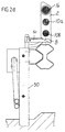
- the segment 9, as shown in Figures 1a, 1b, 2a, 2b and 3 can be the end part of a post P which is designed to be driven directly into the ground, or can be the end part of a bracket S1 for fixing to a metal guardrail 50 or ( Figure 2d) to a bracket S1 for fixing to a concrete guardrail 60.
- the first half-shell 2 On the front surface of the first half-shell 2 there is at least one reflector element, in the specific case two reflecting elements 10a, 10b arranged one above the other, whereas a reflecting element 10c is fitted in the second half-shell 3; the elevation from the ground, the dimensions and the color of the reflector elements 10a, 10b are prescribed by highway code standards.
- Each one of the elements 10a, 10b is circular or polygonal in shape and can be inserted and locked in a respective seat 11 (see Figures 7-8) provided in the surface of the half-shells; the seat 11 has a recess 12 which is shaped so as to match the element 10a, 10b for heat coupling, or optionally coupling by means of an adhesive, of the element 10.
- the seat 11 has, at the center, a complementary stud 13 with a hole 14 for an optional screw 15 for coupling the center of the refractor element 10.
- the reference numeral 16 generally designates a luminous delineator element provided with a dazzle-free (antiglare) light source 17 which is circuitally connected to a power supply designed to be remotely controlled by a monitoring network, optionally a temporary or emergency network, which is capable of driving the frequency and power of the supply according to the environmental conditions (fog, smoke, ash, snow, etcetera).
- a monitoring network optionally a temporary or emergency network, which is capable of driving the frequency and power of the supply according to the environmental conditions (fog, smoke, ash, snow, etcetera).
- the light source 17 is advantageously constituted by a circular or polygonal disk 18 covered by a plurality of very small lamps 19 of the type known as LED, which provide considerable assurances in terms of antiglare, durability and functional strength: moreover, the breakage of some of the lamps does not compromise the operation of the system, offering assurances of maximum safety.
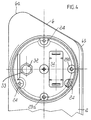
- the element 16 is provided with means for adjusting the relative orientation with respect to the half-shell which comprise a recessed seat 20 of the first half-shell 2 having a certain depth and having, at the center, a conical raised portion 21 ending with a pin 22 and in which the inlet is closed by a transparent disk 23 which can be fixed to the half-shell 2 by means of screws screwed into corresponding perforated studs 24 which are distributed around the seat 20.
- the disk 23 is centrally provided with a complementarily shaped pin 25 which can be coupled to a central hole of the disk 18 being designed to cooperate with the pin 22 in order to support the disk 18 with an adjustable orientation.
- the disk 18 is provided with two perimetric notches 26a and 26b which are mutually spaced by 90 degrees and can be engaged by mushroom-shaped heads 27 of respective adjustment bolts 28 which are screwed into respective studs 29a, 29b which are formed peripherally to the seat and are mutually spaced by 90 degrees.
- the notches 26a and 26b have a helical shape so as to allow, by rotation, easy fitting on the mushroom-shaped heads of the bolts 28.
- the bolts 28 have, on their head, a notch 30 for actuation by means of a screwdriver and have an annular recess for an annular gasket 31 of the type known by the trade-name O-Ring for forming a seal against the respective cylindrical seat: the actuation of one bolt 28 or the other allows to adjust the angle that the axis of the disk 18 forms with respect to the horizontal and vertical plane in order to arrange the disk 18 in the ideal lighting condition with respect to the direction of travel of the vehicles: it is thus possible to provide correct linearity of the light beam produced by the delineators installed in succession.
- the gasket 31 due to its particular concept, ensures, besides to a watertight seal, that the setting of the disk 18 is maintained even in the presence of vibrations caused by the passage of vehicles.
- the seat 20 On the bottom of the seat 20 there is provided a hole 32 for fixing a grommet 33 for the power supply of the light source, and the seat also accommodates a small connecting printed circuit board 34.
- the invention achieves the intended aim and objects, and in particular a safety and warning delineator is provided which combines the characteristics of an ordinary delineator and of a luminous delineator and is adapted to indicate critical points or for luminous guidance and in case of fog or other atmospheric and/or dangerous events: the delineator according to the invention can be installed directly on the ground or coupled to the metallic or concrete guardrails and its indications can be remotely controlled according to environmental conditions and dangers that must be indicated to users.
Landscapes
- Engineering & Computer Science (AREA)
- Architecture (AREA)
- Civil Engineering (AREA)
- Structural Engineering (AREA)
- Road Signs Or Road Markings (AREA)
- Illuminated Signs And Luminous Advertising (AREA)
Applications Claiming Priority (2)
| Application Number | Priority Date | Filing Date | Title |
|---|---|---|---|
| ITBO990250 | 1999-05-13 | ||
| IT1999BO000250A IT1309249B1 (it) | 1999-05-13 | 1999-05-13 | Delineatore stradale di sicurezza ed allarme |
Publications (2)
| Publication Number | Publication Date |
|---|---|
| EP1052335A1 true EP1052335A1 (de) | 2000-11-15 |
| EP1052335B1 EP1052335B1 (de) | 2006-01-04 |
Family
ID=11343979
Family Applications (1)
| Application Number | Title | Priority Date | Filing Date |
|---|---|---|---|
| EP00109059A Expired - Lifetime EP1052335B1 (de) | 1999-05-13 | 2000-04-28 | Sicherheitsleitpfosten und Verkehrswarneinrichtung |
Country Status (5)
| Country | Link |
|---|---|
| EP (1) | EP1052335B1 (de) |
| AT (1) | ATE315133T1 (de) |
| DE (1) | DE60025294D1 (de) |
| ES (1) | ES2254067T3 (de) |
| IT (1) | IT1309249B1 (de) |
Cited By (1)
| Publication number | Priority date | Publication date | Assignee | Title |
|---|---|---|---|---|
| JP2016017261A (ja) * | 2014-07-04 | 2016-02-01 | 名古屋電機工業株式会社 | 発光制御装置、発光制御方法および発光制御システム |
Families Citing this family (1)
| Publication number | Priority date | Publication date | Assignee | Title |
|---|---|---|---|---|
| IT1309249B1 (it) | 1999-05-13 | 2002-01-16 | Conchiglia Spa | Delineatore stradale di sicurezza ed allarme |
Citations (7)
| Publication number | Priority date | Publication date | Assignee | Title |
|---|---|---|---|---|
| US4354772A (en) * | 1979-09-19 | 1982-10-19 | Drexler Joannes H | Road post or reflector post |
| DE8716384U1 (de) * | 1987-12-11 | 1988-02-18 | Peters, Harry, Dipl.-Ing., 4840 Rheda-Wiedenbrück | Leitpfosten |
| DE9111812U1 (de) * | 1991-09-21 | 1991-11-14 | Sauermann, Michael, 4800 Bielefeld | Straßenbegrenzungspfähle mit Beleuchtungseinrichtung |
| US5122939A (en) * | 1991-06-07 | 1992-06-16 | David Kazdan | Safety lighting and reflector system |
| US5580156A (en) * | 1994-09-27 | 1996-12-03 | Koito Manufacturing Co., Ltd. | Marker apparatus |
| WO1998038613A1 (en) * | 1997-02-27 | 1998-09-03 | Star Headlight & Lantern Co., Inc. | Visual signaling device |
| ITBO990250A1 (it) | 1999-05-13 | 2000-11-13 | Conchiglia Spa | Delineatore stradale di sicurezza ed allarme . |
-
1999
- 1999-05-13 IT IT1999BO000250A patent/IT1309249B1/it active
-
2000
- 2000-04-28 EP EP00109059A patent/EP1052335B1/de not_active Expired - Lifetime
- 2000-04-28 AT AT00109059T patent/ATE315133T1/de not_active IP Right Cessation
- 2000-04-28 ES ES00109059T patent/ES2254067T3/es not_active Expired - Lifetime
- 2000-04-28 DE DE60025294T patent/DE60025294D1/de not_active Expired - Lifetime
Patent Citations (7)
| Publication number | Priority date | Publication date | Assignee | Title |
|---|---|---|---|---|
| US4354772A (en) * | 1979-09-19 | 1982-10-19 | Drexler Joannes H | Road post or reflector post |
| DE8716384U1 (de) * | 1987-12-11 | 1988-02-18 | Peters, Harry, Dipl.-Ing., 4840 Rheda-Wiedenbrück | Leitpfosten |
| US5122939A (en) * | 1991-06-07 | 1992-06-16 | David Kazdan | Safety lighting and reflector system |
| DE9111812U1 (de) * | 1991-09-21 | 1991-11-14 | Sauermann, Michael, 4800 Bielefeld | Straßenbegrenzungspfähle mit Beleuchtungseinrichtung |
| US5580156A (en) * | 1994-09-27 | 1996-12-03 | Koito Manufacturing Co., Ltd. | Marker apparatus |
| WO1998038613A1 (en) * | 1997-02-27 | 1998-09-03 | Star Headlight & Lantern Co., Inc. | Visual signaling device |
| ITBO990250A1 (it) | 1999-05-13 | 2000-11-13 | Conchiglia Spa | Delineatore stradale di sicurezza ed allarme . |
Cited By (1)
| Publication number | Priority date | Publication date | Assignee | Title |
|---|---|---|---|---|
| JP2016017261A (ja) * | 2014-07-04 | 2016-02-01 | 名古屋電機工業株式会社 | 発光制御装置、発光制御方法および発光制御システム |
Also Published As
| Publication number | Publication date |
|---|---|
| ES2254067T3 (es) | 2006-06-16 |
| EP1052335B1 (de) | 2006-01-04 |
| ITBO990250A0 (it) | 1999-05-13 |
| ATE315133T1 (de) | 2006-02-15 |
| IT1309249B1 (it) | 2002-01-16 |
| ITBO990250A1 (it) | 2000-11-13 |
| DE60025294D1 (de) | 2006-03-30 |
Similar Documents
| Publication | Publication Date | Title |
|---|---|---|
| KR102296474B1 (ko) | 설치 조정수단을 구비한 도로 표지병 | |
| US11391450B2 (en) | Lighting fixture | |
| KR101081154B1 (ko) | 열발산 구조를 갖춘 엘이디 가로등장치 | |
| US9874338B2 (en) | Universal mounting system for mounting a lighting fixture to a pole | |
| KR102097000B1 (ko) | 도로면으로 보조 교통신호가 조사되는 교통신호장치 | |
| EP3662200B1 (de) | Strassenbeleuchtungs- und eingrenzungssystem | |
| KR100992857B1 (ko) | 램프의 조사각도 조절용 가로등기구 | |
| EP1052335B1 (de) | Sicherheitsleitpfosten und Verkehrswarneinrichtung | |
| AU2004251849B2 (en) | Unidirectional lighting device for illuminating objects and/or for marking lanes, preferably in the airport area | |
| KR100982189B1 (ko) | 각도 조절 가능한 등기구 | |
| KR20120125071A (ko) | 가로등 암대의 연결구조 | |
| KR200196230Y1 (ko) | 가로등의 반사판 조절장치 | |
| US20230003368A1 (en) | Lighting Fixture | |
| KR100693108B1 (ko) | 조사각도 조절이 가능한 태양광 가로등 | |
| KR101732779B1 (ko) | 방향조절이 가능한 난간대를 갖는 안전 난간 | |
| KR20000016408U (ko) | 가로등의 반사판 조절장치 | |
| KR101263724B1 (ko) | 가로등 조사각 조절장치 | |
| KR101128770B1 (ko) | 각도 조절부가 구비된 가로등 | |
| KR200251754Y1 (ko) | 횡단보도 보행자 보호용 조명등 | |
| KR200377499Y1 (ko) | 횡단보도용 조명장치 | |
| KR200193134Y1 (ko) | 보행자 보호용 조명등을 부착한 신호등 철주 조립체 | |
| KR101560567B1 (ko) | 가로등 지주용 연결 고정구 | |
| KR200227077Y1 (ko) | 낙석방지책의 지주 고정장치 | |
| KR200436126Y1 (ko) | 횡단보도 투광기의 브래킷 구조 | |
| EP2803911B1 (de) | LED-Beleuchtung mit verbesserter Lichtverteilung |
Legal Events
| Date | Code | Title | Description |
|---|---|---|---|
| PUAI | Public reference made under article 153(3) epc to a published international application that has entered the european phase |
Free format text: ORIGINAL CODE: 0009012 |
|
| AK | Designated contracting states |
Kind code of ref document: A1 Designated state(s): AT BE CH CY DE DK ES FI FR GB GR IE IT LI LU MC NL PT SE |
|
| AX | Request for extension of the european patent |
Free format text: AL;LT;LV;MK;RO;SI |
|
| 17P | Request for examination filed |
Effective date: 20010502 |
|
| AKX | Designation fees paid |
Free format text: AT BE CH CY DE DK ES FI FR GB GR IE IT LI LU MC NL PT SE |
|
| 17Q | First examination report despatched |
Effective date: 20040809 |
|
| GRAP | Despatch of communication of intention to grant a patent |
Free format text: ORIGINAL CODE: EPIDOSNIGR1 |
|
| GRAS | Grant fee paid |
Free format text: ORIGINAL CODE: EPIDOSNIGR3 |
|
| GRAA | (expected) grant |
Free format text: ORIGINAL CODE: 0009210 |
|
| AK | Designated contracting states |
Kind code of ref document: B1 Designated state(s): AT BE CH CY DE DK ES FI FR GB GR IE IT LI LU MC NL PT SE |
|
| PG25 | Lapsed in a contracting state [announced via postgrant information from national office to epo] |
Ref country code: NL Free format text: LAPSE BECAUSE OF FAILURE TO SUBMIT A TRANSLATION OF THE DESCRIPTION OR TO PAY THE FEE WITHIN THE PRESCRIBED TIME-LIMIT Effective date: 20060104 Ref country code: LI Free format text: LAPSE BECAUSE OF FAILURE TO SUBMIT A TRANSLATION OF THE DESCRIPTION OR TO PAY THE FEE WITHIN THE PRESCRIBED TIME-LIMIT Effective date: 20060104 Ref country code: FI Free format text: LAPSE BECAUSE OF FAILURE TO SUBMIT A TRANSLATION OF THE DESCRIPTION OR TO PAY THE FEE WITHIN THE PRESCRIBED TIME-LIMIT Effective date: 20060104 Ref country code: CH Free format text: LAPSE BECAUSE OF FAILURE TO SUBMIT A TRANSLATION OF THE DESCRIPTION OR TO PAY THE FEE WITHIN THE PRESCRIBED TIME-LIMIT Effective date: 20060104 Ref country code: BE Free format text: LAPSE BECAUSE OF FAILURE TO SUBMIT A TRANSLATION OF THE DESCRIPTION OR TO PAY THE FEE WITHIN THE PRESCRIBED TIME-LIMIT Effective date: 20060104 Ref country code: AT Free format text: LAPSE BECAUSE OF FAILURE TO SUBMIT A TRANSLATION OF THE DESCRIPTION OR TO PAY THE FEE WITHIN THE PRESCRIBED TIME-LIMIT Effective date: 20060104 |
|
| REG | Reference to a national code |
Ref country code: GB Ref legal event code: FG4D |
|
| REG | Reference to a national code |
Ref country code: CH Ref legal event code: EP |
|
| REG | Reference to a national code |
Ref country code: IE Ref legal event code: FG4D |
|
| REF | Corresponds to: |
Ref document number: 60025294 Country of ref document: DE Date of ref document: 20060330 Kind code of ref document: P |
|
| PG25 | Lapsed in a contracting state [announced via postgrant information from national office to epo] |
Ref country code: SE Free format text: LAPSE BECAUSE OF FAILURE TO SUBMIT A TRANSLATION OF THE DESCRIPTION OR TO PAY THE FEE WITHIN THE PRESCRIBED TIME-LIMIT Effective date: 20060404 Ref country code: DK Free format text: LAPSE BECAUSE OF FAILURE TO SUBMIT A TRANSLATION OF THE DESCRIPTION OR TO PAY THE FEE WITHIN THE PRESCRIBED TIME-LIMIT Effective date: 20060404 |
|
| PG25 | Lapsed in a contracting state [announced via postgrant information from national office to epo] |
Ref country code: DE Free format text: LAPSE BECAUSE OF FAILURE TO SUBMIT A TRANSLATION OF THE DESCRIPTION OR TO PAY THE FEE WITHIN THE PRESCRIBED TIME-LIMIT Effective date: 20060405 |
|
| PG25 | Lapsed in a contracting state [announced via postgrant information from national office to epo] |
Ref country code: IE Free format text: LAPSE BECAUSE OF NON-PAYMENT OF DUE FEES Effective date: 20060428 Ref country code: GB Free format text: LAPSE BECAUSE OF NON-PAYMENT OF DUE FEES Effective date: 20060428 |
|
| PG25 | Lapsed in a contracting state [announced via postgrant information from national office to epo] |
Ref country code: MC Free format text: LAPSE BECAUSE OF NON-PAYMENT OF DUE FEES Effective date: 20060430 |
|
| PG25 | Lapsed in a contracting state [announced via postgrant information from national office to epo] |
Ref country code: PT Free format text: LAPSE BECAUSE OF FAILURE TO SUBMIT A TRANSLATION OF THE DESCRIPTION OR TO PAY THE FEE WITHIN THE PRESCRIBED TIME-LIMIT Effective date: 20060605 |
|
| REG | Reference to a national code |
Ref country code: ES Ref legal event code: FG2A Ref document number: 2254067 Country of ref document: ES Kind code of ref document: T3 |
|
| NLV1 | Nl: lapsed or annulled due to failure to fulfill the requirements of art. 29p and 29m of the patents act | ||
| REG | Reference to a national code |
Ref country code: CH Ref legal event code: PL |
|
| PLBE | No opposition filed within time limit |
Free format text: ORIGINAL CODE: 0009261 |
|
| STAA | Information on the status of an ep patent application or granted ep patent |
Free format text: STATUS: NO OPPOSITION FILED WITHIN TIME LIMIT |
|
| 26N | No opposition filed |
Effective date: 20061005 |
|
| GBPC | Gb: european patent ceased through non-payment of renewal fee |
Effective date: 20060428 |
|
| EN | Fr: translation not filed | ||
| PG25 | Lapsed in a contracting state [announced via postgrant information from national office to epo] |
Ref country code: GR Free format text: LAPSE BECAUSE OF FAILURE TO SUBMIT A TRANSLATION OF THE DESCRIPTION OR TO PAY THE FEE WITHIN THE PRESCRIBED TIME-LIMIT Effective date: 20060405 Ref country code: FR Free format text: LAPSE BECAUSE OF FAILURE TO SUBMIT A TRANSLATION OF THE DESCRIPTION OR TO PAY THE FEE WITHIN THE PRESCRIBED TIME-LIMIT Effective date: 20070223 |
|
| PG25 | Lapsed in a contracting state [announced via postgrant information from national office to epo] |
Ref country code: LU Free format text: LAPSE BECAUSE OF NON-PAYMENT OF DUE FEES Effective date: 20060428 |
|
| PG25 | Lapsed in a contracting state [announced via postgrant information from national office to epo] |
Ref country code: FR Free format text: LAPSE BECAUSE OF FAILURE TO SUBMIT A TRANSLATION OF THE DESCRIPTION OR TO PAY THE FEE WITHIN THE PRESCRIBED TIME-LIMIT Effective date: 20060430 |
|
| PG25 | Lapsed in a contracting state [announced via postgrant information from national office to epo] |
Ref country code: FR Free format text: LAPSE BECAUSE OF FAILURE TO SUBMIT A TRANSLATION OF THE DESCRIPTION OR TO PAY THE FEE WITHIN THE PRESCRIBED TIME-LIMIT Effective date: 20060104 Ref country code: CY Free format text: LAPSE BECAUSE OF FAILURE TO SUBMIT A TRANSLATION OF THE DESCRIPTION OR TO PAY THE FEE WITHIN THE PRESCRIBED TIME-LIMIT Effective date: 20060104 |
|
| REG | Reference to a national code |
Ref country code: ES Ref legal event code: PC2A Owner name: DKC EUROPE S.R.L. Effective date: 20180620 Ref country code: ES Ref legal event code: PC2A Effective date: 20180620 |
|
| PGFP | Annual fee paid to national office [announced via postgrant information from national office to epo] |
Ref country code: ES Payment date: 20180503 Year of fee payment: 19 |
|
| PGFP | Annual fee paid to national office [announced via postgrant information from national office to epo] |
Ref country code: IT Payment date: 20190226 Year of fee payment: 20 |
|
| REG | Reference to a national code |
Ref country code: ES Ref legal event code: FD2A Effective date: 20200901 |
|
| PG25 | Lapsed in a contracting state [announced via postgrant information from national office to epo] |
Ref country code: ES Free format text: LAPSE BECAUSE OF NON-PAYMENT OF DUE FEES Effective date: 20190429 |