EP1052394A2 - Moteur multicylindre à combustion interne refroidi par un liquide avec une culasse détachable - Google Patents
Moteur multicylindre à combustion interne refroidi par un liquide avec une culasse détachable Download PDFInfo
- Publication number
- EP1052394A2 EP1052394A2 EP00108214A EP00108214A EP1052394A2 EP 1052394 A2 EP1052394 A2 EP 1052394A2 EP 00108214 A EP00108214 A EP 00108214A EP 00108214 A EP00108214 A EP 00108214A EP 1052394 A2 EP1052394 A2 EP 1052394A2
- Authority
- EP
- European Patent Office
- Prior art keywords
- cylinder head
- cylinder
- internal combustion
- crankcase
- combustion engine
- Prior art date
- Legal status (The legal status is an assumption and is not a legal conclusion. Google has not performed a legal analysis and makes no representation as to the accuracy of the status listed.)
- Granted
Links
- 238000002485 combustion reaction Methods 0.000 title claims abstract description 39
- 239000007788 liquid Substances 0.000 title 1
- 239000002826 coolant Substances 0.000 claims abstract description 63
- 238000009423 ventilation Methods 0.000 claims description 10
- 238000002347 injection Methods 0.000 claims description 7
- 239000007924 injection Substances 0.000 claims description 7
- 230000001174 ascending effect Effects 0.000 claims description 4
- 230000000630 rising effect Effects 0.000 abstract 1
- 238000010438 heat treatment Methods 0.000 description 5
- 238000001816 cooling Methods 0.000 description 2
- 238000011010 flushing procedure Methods 0.000 description 2
- 238000010521 absorption reaction Methods 0.000 description 1
- 230000002411 adverse Effects 0.000 description 1
- 238000000605 extraction Methods 0.000 description 1
- 230000017525 heat dissipation Effects 0.000 description 1
- 238000009434 installation Methods 0.000 description 1
- 239000000243 solution Substances 0.000 description 1
- 238000013022 venting Methods 0.000 description 1
Images
Classifications
-
- F—MECHANICAL ENGINEERING; LIGHTING; HEATING; WEAPONS; BLASTING
- F02—COMBUSTION ENGINES; HOT-GAS OR COMBUSTION-PRODUCT ENGINE PLANTS
- F02F—CYLINDERS, PISTONS OR CASINGS, FOR COMBUSTION ENGINES; ARRANGEMENTS OF SEALINGS IN COMBUSTION ENGINES
- F02F1/00—Cylinders; Cylinder heads
- F02F1/24—Cylinder heads
- F02F1/26—Cylinder heads having cooling means
- F02F1/36—Cylinder heads having cooling means for liquid cooling
- F02F1/40—Cylinder heads having cooling means for liquid cooling cylinder heads with means for directing, guiding, or distributing liquid stream
-
- F—MECHANICAL ENGINEERING; LIGHTING; HEATING; WEAPONS; BLASTING
- F02—COMBUSTION ENGINES; HOT-GAS OR COMBUSTION-PRODUCT ENGINE PLANTS
- F02B—INTERNAL-COMBUSTION PISTON ENGINES; COMBUSTION ENGINES IN GENERAL
- F02B75/00—Other engines
- F02B75/16—Engines characterised by number of cylinders, e.g. single-cylinder engines
- F02B75/18—Multi-cylinder engines
- F02B75/20—Multi-cylinder engines with cylinders all in one line
-
- F—MECHANICAL ENGINEERING; LIGHTING; HEATING; WEAPONS; BLASTING
- F02—COMBUSTION ENGINES; HOT-GAS OR COMBUSTION-PRODUCT ENGINE PLANTS
- F02F—CYLINDERS, PISTONS OR CASINGS, FOR COMBUSTION ENGINES; ARRANGEMENTS OF SEALINGS IN COMBUSTION ENGINES
- F02F1/00—Cylinders; Cylinder heads
- F02F1/02—Cylinders; Cylinder heads having cooling means
- F02F1/10—Cylinders; Cylinder heads having cooling means for liquid cooling
- F02F1/108—Siamese-type cylinders, i.e. cylinders cast together
-
- F—MECHANICAL ENGINEERING; LIGHTING; HEATING; WEAPONS; BLASTING
- F02—COMBUSTION ENGINES; HOT-GAS OR COMBUSTION-PRODUCT ENGINE PLANTS
- F02B—INTERNAL-COMBUSTION PISTON ENGINES; COMBUSTION ENGINES IN GENERAL
- F02B75/00—Other engines
- F02B75/16—Engines characterised by number of cylinders, e.g. single-cylinder engines
- F02B75/18—Multi-cylinder engines
- F02B2075/1804—Number of cylinders
- F02B2075/1816—Number of cylinders four
Definitions
- the invention relates to a Liquid-cooled, multi-cylinder internal combustion engine with a cylinder-crankcase detachably arranged cylinder head comprising respective coolant chambers in the crankcase and cylinder head, with the coolant chamber in the cylinder head of its outer walls, a crankcase-side base plate and a top wall spaced above it is limited, and by means of transverse walls is divided into sections each assigned to a cylinder-side combustion chamber, the gas exchange channels flowing across the cylinder head in the sections and receptacles for spark plugs and / or injection nozzles Coolant adjacent in the base plate of a long side of the cylinder head arranged openings flows towards the cylinder crankcase.
- Such an internal combustion engine shows and describes DE 196 08 576 C1, wherein the desired turbulent cross-flow is caused by the transfer of coolant from a partial area of a divided coolant chamber of the cylinder crankcase. Via a special ventilation of the cross nothing flows through the cylinder head.
- a liquid-cooled internal combustion engine is known from DE 195 08 985 C1 with a cylinder head for an inclined cylinder crankcase, whereby the coolant chamber of the cylinder head through an intermediate ceiling in superimposed Sections is divided. To vent this cylinder head with a subdivision of the coolant chamber provided in the machine longitudinal direction ventilation ducts extending over the length of the cylinder head are provided.
- the cylinder head known from DE 1 214 935 B1 shows a relative free arrangement of injection nozzle and / or spark plug on one long side. This is achieved with the liquid-cooled cylinder head in that the coolant pressed into the coolant chamber of the cylinder crankcase through openings in the base plate of this cylinder head in the Coolant space enters and via a separate, inserted dip tube to one Return line arranged on the outside of the cylinder head is discharged to a cooler is. Furthermore, a geodetic high area of the cylinder head is a vent or a steam vent is provided in the dip tube.
- DE 36 29 671 A1 describes a single cylinder head for a cylinder tube a liquid-cooled internal combustion engine known, which in one helical channel around the cylinder tube led coolant on the cylinder head side End via a riser duct built into the cylinder head to a die Single cylinder heads connecting manifold leads away. Venting measures the coolant rooms are not mentioned.
- the invention has for its object in a generic internal combustion engine the coolant flow with the inclusion of at least one partial area to design a divided coolant chamber of the cylinder crankcase in such a way that with a simple design, an effective ventilation of a cross flowed through cylinder head is achieved.
- the cylinder crankcase divided into sections Coolant chamber comprises and that one arranged in the cylinder crankcase Setting up the forwarding of the coolant flowing out of the cylinder head an ascending channel integrated in the cylinder head, one in the cylinder head Vent line connecting sections of this coolant chamber at high points is provided which in the riser duct connectable to an outer line connection culminates in an area of a geodetic peak.
- the device is in the cylinder crankcase separately trained or integrated collecting channel.
- the one with the Integrated ascending duct in the cylinder head connected collecting duct carrying coolant in the cylinder crankcase results in a cost-effective version without additional Components and advantageously increases the sound absorption on the cylinder crankcase.
- the cross-flow cylinder head can collect from a discharge side Part of a divided coolant chamber of the cylinder crankcase supplied be and / or also through a longitudinal channel arranged on the cylinder head according to a further proposal of the invention.
- a correspondingly deep training Collecting channel can be made relatively narrow, so that in advantageously only a minimal widening of the cylinder head and the Cylinder crankcase results.
- the collecting duct is above wall openings with a portion of the divided coolant chamber of the cylinder crankcase in connection.
- the collecting duct stands over the wall openings with an inlet side Part of the coolant chamber of the crankcase in connection with the advantage that this sub-area in full load operation of the internal combustion engine is rinsed.
- a Main supply through a longitudinal supply duct arranged on the cylinder head over a small number of openings of a relatively small diameter be connected to the coolant chamber sections in the cylinder head.
- collecting channel is achieved in that the Collection channel over an openly designed long side with a section of the subdivided Coolant chamber of the cylinder crankcase communicates.
- a partial area of a coolant chamber preferably subdivided by the cylinders serve the cylinder crankcase.
- All of the aforementioned configurations of the collecting duct arranged according to the invention can advantageously be combined with at least one in the cylinder head integrated ascending duct arranged in an end region.
- the cylinder head has in both end regions an integrated riser, with the advantage that for transverse or longitudinal installation the internal combustion engine each achieved an optimized radiator flow connection is. This advantageously results in largely the same flow conditions in the differently arranged cylinder heads, whereby for both types of connection the radiator supply lines each have the same cylinder head in an advantageous manner Is used.
- that of the front Front side of the internal combustion engine has an adjacent riser duct with one in the cylinder head Integrated short-circuit duct to a pump connection piece arranged on the cylinder head in connection. This is for one on the side of the internal combustion engine arranged coolant pump an externally laid, over the front the short-circuit line to be led away from the internal combustion engine and thus if necessary, shortens the overall length of the internal combustion engine.
- the invention is advantageous for a liquid-cooled internal combustion engine a uniform cylinder head for a longitudinally installed as well as for reached a transversely installed internal combustion engine, with which in the transversely flowed through cylinder head integrated ventilation line with a geodetic Peak connection in on the integrated riser for each of the predetermined a safe ventilation when filling as well as a safe Steam extraction is ensured during hot operation of the internal combustion engine.
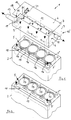
- the coolant chamber 4 in the cylinder head 3 is from the outer walls, a crankcase side Base plate 6 and a spaced above it Cover wall 7 limited and by means of transverse walls, not shown, in one cylinder side Sections 8, 8 ', 8' ', 8' '' assigned to the combustion chamber are subdivided; Sections 8 to 8 '' 'through the cylinder head 3, not shown Gas exchange channels and receptacles for spark plugs and / or injection nozzles Coolant in the bottom plate 6 of a long side of the cylinder head 3 perforations 9 arranged adjacent in the direction of the cylinder crankcase 2 flows off.
- the invention proposes that the cylinder head crankcase 2 divided into sections 5 ', 5' ' Coolant chamber 5 includes and that one arranged in the cylinder crankcase 2 Device 10 for forwarding the coolant flowing out of the cylinder head 3 to an integrated in the cylinder head 3 riser 11, one in Cylinder head 3 sections 8 to 8 '' 'of this coolant chamber 4 in high points connecting vent line 12 is provided, which in the with an outer Line connection 13 connectable riser 11 in a geodetic area Peak 14 ends.
- the device 10 can be in a cylinder crankcase 2 separately trained or integrated collection channel 15 without connection to one of the partial areas 5 ', 5' 'of the coolant chamber 5 of the cylinder crankcase 2nd
- FIG. 1 shows a preferred embodiment of the collecting duct 15, the preferably provided on the inlet side in the internal combustion engine 1 collection channel 15 through wall openings 16 with an inlet-side portion 5 'of the divided Coolant chamber 5 of the cylinder crankcase 2 is connected.
- the collecting duct 15 can be open via a designed long side with a portion 5 'or 5' 'of the divided coolant chamber 5 of the cylinder crankcase 2 are connected.
- Coolant flowing out of the cylinder head 3 can be passed on Device 10 is a partial area 5 ′ or 5 ′′ of a section divided over the cylinders 17 Coolant chamber 5 of the cylinder crankcase 2 serve the advantage the least effort.
- Supply longitudinal channel to be supplied can according to the DE 198 02 060 can be formed.
- a tap can also be provided for a vehicle heating flow.
Landscapes
- Engineering & Computer Science (AREA)
- Chemical & Material Sciences (AREA)
- Combustion & Propulsion (AREA)
- Mechanical Engineering (AREA)
- General Engineering & Computer Science (AREA)
- Cylinder Crankcases Of Internal Combustion Engines (AREA)
Applications Claiming Priority (2)
| Application Number | Priority Date | Filing Date | Title |
|---|---|---|---|
| DE19922342 | 1999-05-14 | ||
| DE19922342A DE19922342A1 (de) | 1999-05-14 | 1999-05-14 | Flüssigkeitsgekühlte, mehrzylindrige Brennkraftmaschine mit am Zylinder-Kurbelgehäuse lösbar angeordnetem Zylinderkopf |
Publications (3)
| Publication Number | Publication Date |
|---|---|
| EP1052394A2 true EP1052394A2 (fr) | 2000-11-15 |
| EP1052394A3 EP1052394A3 (fr) | 2001-02-07 |
| EP1052394B1 EP1052394B1 (fr) | 2004-07-21 |
Family
ID=7908132
Family Applications (1)
| Application Number | Title | Priority Date | Filing Date |
|---|---|---|---|
| EP00108214A Expired - Lifetime EP1052394B1 (fr) | 1999-05-14 | 2000-04-14 | Moteur multicylindre à combustion interne refroidi par un liquide avec une culasse détachable |
Country Status (3)
| Country | Link |
|---|---|
| EP (1) | EP1052394B1 (fr) |
| DE (2) | DE19922342A1 (fr) |
| ES (1) | ES2222868T3 (fr) |
Cited By (7)
| Publication number | Priority date | Publication date | Assignee | Title |
|---|---|---|---|---|
| EP1522709A3 (fr) * | 2003-10-10 | 2005-05-04 | Aichi Kikai Kogyo Kabushiki Kaisha | Conduit de refroidissement pour des moteurs à combustion interne |
| WO2009007143A1 (fr) * | 2007-07-06 | 2009-01-15 | Brp-Rotax Gmbh & Co. Kg | Système de refroidissement d'un moteur à combustion interne |
| WO2010031423A1 (fr) * | 2008-09-22 | 2010-03-25 | Fev Motorentechnik Gmbh | Dispositif de refroidissement, circuit de refroidissement et procédé de refroidissement pour un moteur à combustion interne |
| EP2392813A1 (fr) * | 2010-06-03 | 2011-12-07 | Peugeot Citroën Automobiles SA | Culasse, noyau pour la fabrication de cette culasse, procédé de fabrication de cette culasse, et véhicule |
| AT514793A1 (de) * | 2013-09-16 | 2015-03-15 | Avl List Gmbh | Kühlsystem für eine Brennkraftmaschine |
| EP3379063A1 (fr) * | 2017-03-22 | 2018-09-26 | Liebherr-Machines Bulle SA | Moteur à combustion interne à refroidissement par liquide |
| DE102020114716A1 (de) | 2020-06-03 | 2021-12-09 | Bayerische Motoren Werke Aktiengesellschaft | Zylinderkurbelgehäuse mit zumindest einem Steigkanal und Verbrennungskraftmaschine mit einem Zylinderkurbelgehäuse |
Families Citing this family (3)
| Publication number | Priority date | Publication date | Assignee | Title |
|---|---|---|---|---|
| DE102007027719B4 (de) * | 2007-06-15 | 2015-05-13 | Audi Ag | Brennkraftmaschine mit einem Heizungskreislauf und einem Kühlkreislauf |
| DE102009023530A1 (de) * | 2009-05-30 | 2010-12-02 | Bayerische Motoren Werke Aktiengesellschaft | Flüssigkeitsgekühlte Brennkraftmaschine |
| DE102010023812A1 (de) | 2010-06-15 | 2011-12-15 | Audi Ag | Mehrzylinder-Brennkraftmaschine mit getrennter Zylinderkurbelgehäuse-/Zylinderkopfkühlung |
Citations (7)
| Publication number | Priority date | Publication date | Assignee | Title |
|---|---|---|---|---|
| DE1214935B (de) | 1960-11-25 | 1966-04-21 | Maschf Augsburg Nuernberg Ag | Aus einem Stueck gegossener Zylinderkopf schnellaufender, fluessigkeitsgekuehlter Hochleistungs-Dieselmotoren |
| DE2928298A1 (de) | 1979-07-13 | 1981-01-22 | Audi Nsu Auto Union Ag | Fluessigkeitsgekuehlte brennkraftmaschine |
| DE8621654U1 (de) | 1986-08-12 | 1986-09-25 | Dr.Ing.H.C. F. Porsche Ag, 7000 Stuttgart | Zylinderkopf für eine flüssigkeitsgekühlte Brennkraftmaschine |
| DE3629671A1 (de) | 1986-09-01 | 1988-03-10 | Kloeckner Humboldt Deutz Ag | Brennkraftmaschine mit fluessigkeitsgekuehlter zylinderlaufbuechse |
| JPH0533646A (ja) | 1991-07-29 | 1993-02-09 | Mazda Motor Corp | エンジンの冷却構造 |
| DE19508985C1 (de) | 1995-03-13 | 1996-07-25 | Daimler Benz Ag | Zylinderkopf für eine flüssigkeitsgekühlte Brennkraftmaschine |
| DE19608576C1 (de) | 1996-03-06 | 1997-06-19 | Daimler Benz Ag | Flüssigkeitsgekühlter Zylinderkopf für eine mehrzylindrige Brennkraftmaschine |
Family Cites Families (4)
| Publication number | Priority date | Publication date | Assignee | Title |
|---|---|---|---|---|
| DE1301628B (de) * | 1964-08-27 | 1969-08-21 | Kloeckner Humboldt Deutz Ag | Zylinderkopf fuer wassergekuehlte Hubkolbenbrennkraftmaschinen |
| DE1937146A1 (de) * | 1969-07-22 | 1971-02-04 | Daimler Benz Ag | Kuehlwasserfuehrung bei Hubkolbenbrennkraftmaschinen |
| IT7453689U1 (it) * | 1974-12-19 | 1976-06-19 | Fiat Spa | Perfezionamento nel raffreddamento dei cilindri per motori a combustione interna a ciclo diesel |
| GB9012364D0 (en) * | 1990-06-02 | 1990-07-25 | Jaguar Cars | Engine cooling systems |
-
1999
- 1999-05-14 DE DE19922342A patent/DE19922342A1/de not_active Withdrawn
-
2000
- 2000-04-14 DE DE50007104T patent/DE50007104D1/de not_active Expired - Lifetime
- 2000-04-14 ES ES00108214T patent/ES2222868T3/es not_active Expired - Lifetime
- 2000-04-14 EP EP00108214A patent/EP1052394B1/fr not_active Expired - Lifetime
Patent Citations (7)
| Publication number | Priority date | Publication date | Assignee | Title |
|---|---|---|---|---|
| DE1214935B (de) | 1960-11-25 | 1966-04-21 | Maschf Augsburg Nuernberg Ag | Aus einem Stueck gegossener Zylinderkopf schnellaufender, fluessigkeitsgekuehlter Hochleistungs-Dieselmotoren |
| DE2928298A1 (de) | 1979-07-13 | 1981-01-22 | Audi Nsu Auto Union Ag | Fluessigkeitsgekuehlte brennkraftmaschine |
| DE8621654U1 (de) | 1986-08-12 | 1986-09-25 | Dr.Ing.H.C. F. Porsche Ag, 7000 Stuttgart | Zylinderkopf für eine flüssigkeitsgekühlte Brennkraftmaschine |
| DE3629671A1 (de) | 1986-09-01 | 1988-03-10 | Kloeckner Humboldt Deutz Ag | Brennkraftmaschine mit fluessigkeitsgekuehlter zylinderlaufbuechse |
| JPH0533646A (ja) | 1991-07-29 | 1993-02-09 | Mazda Motor Corp | エンジンの冷却構造 |
| DE19508985C1 (de) | 1995-03-13 | 1996-07-25 | Daimler Benz Ag | Zylinderkopf für eine flüssigkeitsgekühlte Brennkraftmaschine |
| DE19608576C1 (de) | 1996-03-06 | 1997-06-19 | Daimler Benz Ag | Flüssigkeitsgekühlter Zylinderkopf für eine mehrzylindrige Brennkraftmaschine |
Cited By (17)
| Publication number | Priority date | Publication date | Assignee | Title |
|---|---|---|---|---|
| EP1522709A3 (fr) * | 2003-10-10 | 2005-05-04 | Aichi Kikai Kogyo Kabushiki Kaisha | Conduit de refroidissement pour des moteurs à combustion interne |
| US7930999B2 (en) | 2003-10-10 | 2011-04-26 | Nissan Motor Co., Ltd. | Cooling water passage structure of internal combustion engines |
| WO2009007143A1 (fr) * | 2007-07-06 | 2009-01-15 | Brp-Rotax Gmbh & Co. Kg | Système de refroidissement d'un moteur à combustion interne |
| US7845316B2 (en) | 2007-07-06 | 2010-12-07 | Brp-Powertrain Gmbh & Co Kg | Internal combustion engine cooling system |
| CN101688464B (zh) * | 2007-07-06 | 2012-05-23 | Brp罗泰克斯有限两合公司 | 内燃发动机冷却系统 |
| WO2010031423A1 (fr) * | 2008-09-22 | 2010-03-25 | Fev Motorentechnik Gmbh | Dispositif de refroidissement, circuit de refroidissement et procédé de refroidissement pour un moteur à combustion interne |
| EP2392813A1 (fr) * | 2010-06-03 | 2011-12-07 | Peugeot Citroën Automobiles SA | Culasse, noyau pour la fabrication de cette culasse, procédé de fabrication de cette culasse, et véhicule |
| FR2960916A1 (fr) * | 2010-06-03 | 2011-12-09 | Peugeot Citroen Automobiles Sa | Culasse, noyau pour la fabrication de cette culasse, procede de fabrication de cette culasse, et vehicule |
| AT514793A1 (de) * | 2013-09-16 | 2015-03-15 | Avl List Gmbh | Kühlsystem für eine Brennkraftmaschine |
| AT514793B1 (de) * | 2013-09-16 | 2015-06-15 | Avl List Gmbh | Kühlsystem für eine Brennkraftmaschine |
| EP3379063A1 (fr) * | 2017-03-22 | 2018-09-26 | Liebherr-Machines Bulle SA | Moteur à combustion interne à refroidissement par liquide |
| CH713618A1 (de) * | 2017-03-22 | 2018-09-28 | Liebherr Machines Bulle Sa | Flüssigkeitsgekühlter Verbrennungsmotor. |
| US10662857B2 (en) | 2017-03-22 | 2020-05-26 | Liebherr Machines Bulle Sa | Liquid-cooled internal combustion engine |
| US11248514B2 (en) | 2017-03-22 | 2022-02-15 | Liebherr Machines Bulle Sa | Liquid-cooled internal combustion engine |
| DE102020114716A1 (de) | 2020-06-03 | 2021-12-09 | Bayerische Motoren Werke Aktiengesellschaft | Zylinderkurbelgehäuse mit zumindest einem Steigkanal und Verbrennungskraftmaschine mit einem Zylinderkurbelgehäuse |
| WO2021244809A1 (fr) | 2020-06-03 | 2021-12-09 | Bayerische Motoren Werke Aktiengesellschaft | Carter de cylindre comportant au moins un conduit de colonne montante et moteur à combustion interne comprenant un carter de cylindre |
| US11939893B2 (en) | 2020-06-03 | 2024-03-26 | Bayerische Motoren Werke Aktiengesellschaft | Cylinder crankcase having at least one riser duct and internal combustion engine comprising a cylinder crankcase |
Also Published As
| Publication number | Publication date |
|---|---|
| ES2222868T3 (es) | 2005-02-16 |
| EP1052394A3 (fr) | 2001-02-07 |
| DE19922342A1 (de) | 2000-11-16 |
| DE50007104D1 (de) | 2004-08-26 |
| EP1052394B1 (fr) | 2004-07-21 |
Similar Documents
| Publication | Publication Date | Title |
|---|---|---|
| DE60003883T2 (de) | Kühlsystem für ruckgeführtes Abgas und Öl | |
| DE112010001720B4 (de) | Kühlmittelkanalanordnung für einen Zylinderkopf einer Brennkraftmaschine | |
| DE60214279T2 (de) | Wassergekühlte Brennkraftmaschine | |
| EP0784150B1 (fr) | Bloc à cylindres d'un moteur à combustion interne multicylindre | |
| AT5301U1 (de) | Zylinderkopf für mehrere zylinder | |
| DE2950905A1 (de) | Kuehleinrichtung sowie zylinderkopf fuer verbrennungsmotor | |
| DE19654451C1 (de) | Flüssigkeitsgekühlte Mehrzylinder-Brennkraftmaschine | |
| DE10344834B4 (de) | Motorkühlsystem | |
| DE102004032653B4 (de) | Zylinderkopfstruktur eines Motors | |
| EP1052394A2 (fr) | Moteur multicylindre à combustion interne refroidi par un liquide avec une culasse détachable | |
| DE102008047185A1 (de) | Kühlmittelströmungsweganordnung eines Zylinderkopfes einer Brennkraftmaschine und Verfahren zu dessen Kühlung | |
| DE4342800A1 (de) | Hubkolbenbrennkraftmaschine | |
| DE10117090B4 (de) | Wassergekühlte, mehrzylindrige Brennkraftmaschine | |
| DE69105633T2 (de) | Kühlungsanlage für Brennkraftmaschinen. | |
| DE112004002081B4 (de) | Brennkraftmaschine | |
| DE10222078A1 (de) | Mehrzylindermotor | |
| DE19701543B4 (de) | Kühlanordnung in einem Motorblock | |
| DE2739605C3 (de) | Ansaugkasten für Brennkraftmaschinen | |
| DE4001140C1 (en) | Cylinder block for liquid cooled IC engine - has coolant channels in internal angle of V=shaped block | |
| EP0933510B1 (fr) | Moteur à combustion interne | |
| DE4322030A1 (de) | Brennkraftmaschine mit zwei Zylinderreihen | |
| DE10060682A1 (de) | Zylinderkopf für eine Brennkraftmaschine | |
| EP1103704A2 (fr) | Moteur à combustion refroidi par liquide avec les bancs-cylindres rangés en V | |
| EP0999353B1 (fr) | Carter de machine en fonte pour des moteurs à refroidissement forcée avec système de lubrification, particulièrement avec des cylindres en ligne | |
| DE10161553A1 (de) | Zylinderblock für eine flüssigkeitsgekühlte Brennkraftmaschine |
Legal Events
| Date | Code | Title | Description |
|---|---|---|---|
| PUAI | Public reference made under article 153(3) epc to a published international application that has entered the european phase |
Free format text: ORIGINAL CODE: 0009012 |
|
| AK | Designated contracting states |
Kind code of ref document: A2 Designated state(s): DE ES FR GB IT |
|
| AX | Request for extension of the european patent |
Free format text: AL;LT;LV;MK;RO;SI |
|
| PUAL | Search report despatched |
Free format text: ORIGINAL CODE: 0009013 |
|
| AK | Designated contracting states |
Kind code of ref document: A3 Designated state(s): AT BE CH CY DE DK ES FI FR GB GR IE IT LI LU MC NL PT SE |
|
| AX | Request for extension of the european patent |
Free format text: AL;LT;LV;MK;RO;SI |
|
| RIC1 | Information provided on ipc code assigned before grant |
Free format text: 7F 02F 1/40 A, 7F 02F 1/10 B, 7F 02B 75/20 B |
|
| 17P | Request for examination filed |
Effective date: 20010222 |
|
| AKX | Designation fees paid |
Free format text: DE ES FR GB IT |
|
| GRAP | Despatch of communication of intention to grant a patent |
Free format text: ORIGINAL CODE: EPIDOSNIGR1 |
|
| GRAS | Grant fee paid |
Free format text: ORIGINAL CODE: EPIDOSNIGR3 |
|
| GRAA | (expected) grant |
Free format text: ORIGINAL CODE: 0009210 |
|
| AK | Designated contracting states |
Kind code of ref document: B1 Designated state(s): DE ES FR GB IT |
|
| REG | Reference to a national code |
Ref country code: GB Ref legal event code: FG4D Free format text: NOT ENGLISH |
|
| GBT | Gb: translation of ep patent filed (gb section 77(6)(a)/1977) |
Effective date: 20040721 |
|
| REF | Corresponds to: |
Ref document number: 50007104 Country of ref document: DE Date of ref document: 20040826 Kind code of ref document: P |
|
| ET | Fr: translation filed | ||
| REG | Reference to a national code |
Ref country code: ES Ref legal event code: FG2A Ref document number: 2222868 Country of ref document: ES Kind code of ref document: T3 |
|
| PLBE | No opposition filed within time limit |
Free format text: ORIGINAL CODE: 0009261 |
|
| STAA | Information on the status of an ep patent application or granted ep patent |
Free format text: STATUS: NO OPPOSITION FILED WITHIN TIME LIMIT |
|
| 26N | No opposition filed |
Effective date: 20050422 |
|
| REG | Reference to a national code |
Ref country code: FR Ref legal event code: PLFP Year of fee payment: 17 |
|
| REG | Reference to a national code |
Ref country code: FR Ref legal event code: PLFP Year of fee payment: 18 |
|
| REG | Reference to a national code |
Ref country code: FR Ref legal event code: PLFP Year of fee payment: 19 |
|
| PGFP | Annual fee paid to national office [announced via postgrant information from national office to epo] |
Ref country code: ES Payment date: 20190520 Year of fee payment: 20 Ref country code: DE Payment date: 20190410 Year of fee payment: 20 Ref country code: IT Payment date: 20190419 Year of fee payment: 20 |
|
| PGFP | Annual fee paid to national office [announced via postgrant information from national office to epo] |
Ref country code: FR Payment date: 20190423 Year of fee payment: 20 |
|
| PGFP | Annual fee paid to national office [announced via postgrant information from national office to epo] |
Ref country code: GB Payment date: 20190424 Year of fee payment: 20 |
|
| REG | Reference to a national code |
Ref country code: DE Ref legal event code: R071 Ref document number: 50007104 Country of ref document: DE |
|
| REG | Reference to a national code |
Ref country code: GB Ref legal event code: PE20 Expiry date: 20200413 |
|
| PG25 | Lapsed in a contracting state [announced via postgrant information from national office to epo] |
Ref country code: GB Free format text: LAPSE BECAUSE OF EXPIRATION OF PROTECTION Effective date: 20200413 |
|
| REG | Reference to a national code |
Ref country code: ES Ref legal event code: FD2A Effective date: 20220128 |
|
| PG25 | Lapsed in a contracting state [announced via postgrant information from national office to epo] |
Ref country code: ES Free format text: LAPSE BECAUSE OF EXPIRATION OF PROTECTION Effective date: 20200415 |
|
| P01 | Opt-out of the competence of the unified patent court (upc) registered |
Effective date: 20230502 |