EP1052418A2 - Kugelgelenk - Google Patents
Kugelgelenk Download PDFInfo
- Publication number
- EP1052418A2 EP1052418A2 EP00109885A EP00109885A EP1052418A2 EP 1052418 A2 EP1052418 A2 EP 1052418A2 EP 00109885 A EP00109885 A EP 00109885A EP 00109885 A EP00109885 A EP 00109885A EP 1052418 A2 EP1052418 A2 EP 1052418A2
- Authority
- EP
- European Patent Office
- Prior art keywords
- ball joint
- retaining ring
- joint according
- ball
- sealing bellows
- Prior art date
- Legal status (The legal status is an assumption and is not a legal conclusion. Google has not performed a legal analysis and makes no representation as to the accuracy of the status listed.)
- Granted
Links
Images


Classifications
-
- F—MECHANICAL ENGINEERING; LIGHTING; HEATING; WEAPONS; BLASTING
- F16—ENGINEERING ELEMENTS AND UNITS; GENERAL MEASURES FOR PRODUCING AND MAINTAINING EFFECTIVE FUNCTIONING OF MACHINES OR INSTALLATIONS; THERMAL INSULATION IN GENERAL
- F16C—SHAFTS; FLEXIBLE SHAFTS; ELEMENTS OR CRANKSHAFT MECHANISMS; ROTARY BODIES OTHER THAN GEARING ELEMENTS; BEARINGS
- F16C11/00—Pivots; Pivotal connections
- F16C11/04—Pivotal connections
- F16C11/06—Ball-joints; Other joints having more than one degree of angular freedom, i.e. universal joints
- F16C11/0666—Sealing means between the socket and the inner member shaft
- F16C11/0671—Sealing means between the socket and the inner member shaft allowing operative relative movement of joint parts due to flexing of the sealing means
Definitions
- the invention relates to a ball joint according to the preamble of claim 1.
- Ball joints of this type are used, for example, for wheel suspensions of motor vehicles used.
- the basic structure is largely identical.
- a generic ball joint can be found in DE 36 32 265 C1. To the relative to seal mutually movable ball joint components from the environment a bellows is inserted between the housing and the ball stud. This is for Joint lubrication filled with grease. The sealing bellows is with its pin-side Edge area only partially in an L-shaped retaining ring seen in cross section on the Ball stud set.
- a retaining ring is known from SUI-PS 465 971, which is stuck is arranged on the ball stud and slidably receives the sealing bellows edge.
- the script shows a ball joint, which consists of a housing and an in the housing rotatably and tiltably mounted ball pin is on its shaft fixed retaining ring is arranged. Seen in cross section an L-shaped shape having retaining ring thus has an axial jacket and an approximately perpendicular thereto running radial collar.
- a sealing bellows used to seal the joint between the Ball joint housing and the retaining ring firmly attached to the ball pin a sealing bellows used.
- a retaining ring is used to generate a pressure force of the sealing bellows edge against the latter. Nevertheless, according to the Disclosure of said document the sealing bellows edge area sliding in the retaining ring be included.
- the invention is based on the technical problem of creating a ball joint, that with few individual parts an optimal sealing function of the relative to each other allows movable ball joint components to the environment and thereby simple and is inexpensive to manufacture.
- the radial collar of the retaining ring it is proposed on the radial collar of the retaining ring to form a ring collar in one piece, which in the edge region of the sealing bellows intervenes.
- a retaining ring according to the invention that is stuck on the ball stud is arranged, it becomes possible to both the sealing bellows edge area to fix in position on the housing as well as on the retaining ring, i.e. on the pin side.
- additional machine elements for fixing the sealing bellows edge area such as For example, clamping rings can be saved in whole or in part.
- the ball joint can so that overall production is easier and cheaper.
- Embodiment of the invention proposed the ring collar and / or the radial collar through to divide slots distributed over their circumference into individual segments so that at Place the retaining ring on the ball stud an elastic preload in the retaining ring is generated and this fits tightly on the ball stud.
- the amount of preload is measured according to the elasticity of the material used for the retaining ring.
- the radial collar designed to be elastically deformable.
- the elastic deformability can continue be improved that the radial collar at least a narrow section with a has reduced cross-section, which thus forms a hinge joint.
- the retaining ring preferably in the region of the radial collar reinforcing inserts to form.
- the retaining ring made of plastic, for example, can already during of its manufacturing process are provided with the inserts mentioned. Overall will this also improves the elasticity of the retaining ring.
- the assembly of a ball joint according to the invention can be carried out as follows: First, the housing and the ball pin are assembled in themselves known way. A bearing shell can be made between the housing and the joint ball Plastic can be provided. Then the sealing bellows on the housing, for example by means of conventional clamping means, such as one or more clamping rings. Then the retaining ring on the connecting side of the ball stud Ball pin pushed. The collar of the retaining ring is in the for Edge area of the sealing bellows introduced groove-shaped recess. Then the pin of the ball joint is in the prepared holder of the Motor vehicle component used and from the underside of the motor vehicle component locked by a screw connection. During the screwing of the ball pin this pulls increasingly into the motor vehicle component.
- the Invention also a sealing lip on the radially outer region of the sealing bellows edge region be molded on. This sealing lip creates a wiping effect.
- the spacer sleeve is supported accordingly with its side facing away from the retaining ring on the underside of the joint ball.
- the retaining ring thus merges into the spacer sleeve above its axial jacket.
- the Transition area between the axial jacket and spacer sleeve can also be a Cross section seen wedge-shaped portion that forms a sliding surface.
- the pin-side sealing bellows edge area slides during the Assembly process over the sliding surface of the connection area on the ball stud pushed on retaining ring and initially loosely moves into the designated holder of the Retaining ring. While tightening the ball stud in the previously described The radial collar of the retaining ring is elastically deformed and thus the Sealing bellows edge area increasingly pressed in the centripetal direction against the retaining ring. Due to the wedge-shaped cross-section of the sliding surface above the axial jacket Sealing bellows edge area in an approximately U-shaped annular groove of the retaining ring and is thus optimally fixed in its position.
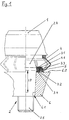
- FIGs 1 to 3 each show ball joints according to the invention in partial section differently designed retaining rings, while in FIG enlarged view of the sealing bellows edge area is shown, the execution of which Ball joint shown in Figure 1 corresponds.
- the ball joints shown in the figures each have a housing 1 in which a Ball pin 2 is rotatable and tiltable. Storage can be done in a manner known per se Way over a bearing shell made of plastic or in another way.
- the Ball pin itself consists of a ball 2.2 mounted in the housing, the is not shown for simplicity in the figures and one on the joint ball subsequent shaft 2.1.
- the part of the ball pin designated overall as shaft 2.1 2 in turn has a conical chamfer 2.3 below the joint ball 2.2
- Between the joint ball 2.2 and the conical section 2.3 of the ball pin 2 is a Transitional area 2.4 available.
- the conical section 2.3 is included Connection area 2.5 on.
- a sealing bellows 4 is fixed on the one hand on the housing 1 and on the other hand in one Retaining ring 3 inserted.
- the retaining ring has an adjoining the shaft 2.1 Axial jacket 3.1 and a radial collar 3.2 running approximately at right angles thereto.
- the Radial collar 3.2 is in the execution according to the illustration in Figure 1 or in Figure 4 at least partially reduced in its cross section, so that it is a hinge joint 3.4 forms.
- a reinforcing insert 5 is molded in the radial collar as well as on the one adjoining the radial collar Ring collar 3.3 of the retaining ring 3, a reinforcing insert 5 is molded.
- the ring band 3.3 engages in a complementarily designed recess 4.2 of the edge area 4.1 of the Sealing bellows 4 a.
- the ball pin is with its conical section 2.3 in a designated Receiving opening 6.1 of a motor vehicle component 6 used. This section penetrates the motor vehicle component completely, so that below the above Motor vehicle component 6 of the connection area 2.5 emerges, which by means of a Screw connection the fixing of the ball joint on the motor vehicle component enables.
- FIGS. 1 and 4 the preassembled state of the retaining ring 3 is still schematic drawn. This was due to the non-hatched radial collar 3.2 and ring collar 3.3 or the non-hatched sealing lip 4.3.
- the ball pin 2 in the receiving opening 6.1 of the motor vehicle component 6 is drawn.
- the radial collar 3.2 and the ring collar 3.3 of the retaining ring 3 deformed such that they rest against the retaining ring Area of the edge area 4.1 of the sealing bellows 4 against the axial jacket 3.1 of the Press retaining rings 3. This creates a static, very effective sealing connection created.
- the axial jacket 3.1 of the Retaining rings 3 additionally equipped with a sawtooth-like contour. This participates a complementarily shaped contour of the edge area 4.1 of the sealing bellows together.
- the thus created larger surface improves the sealing effect of the Overall system significantly compared to the previously described solution.
- the collar 3.3 engages in one complementary recording 4.2 of the sealing bellows edge area 4.1.
- no reinforcing inserts 5 are provided. The sealing effect and The sealing bellows edge area is held here exclusively by the Material elasticity of the retaining ring 3 reached.
- FIG. 3 A special embodiment of a ball joint according to the invention is shown in the Representation of Figure 3.
- the retaining ring 3 has a sliding surface 8.
- This in Cross-section wedge-shaped sliding surface 8 enables simplified assembly of the Bellow edge area 4.1. So the ball joint is already in the beginning described manner connected to the bellows and only then is the Underside, that is, from the connection area 2.5 of the ball pin 2, the retaining ring 3 on the Ball stud pushed on.
- the retaining ring 3 engages in the receiving opening of the Sealing bellows 4 and the sealing bellows edge area 4.1 slide over the sliding surface 8 away and becomes during the locking of the ball pin 2 on the motor vehicle component 6 pressed into the retaining ring receiving area due to its inherent elasticity.
Landscapes
- Engineering & Computer Science (AREA)
- General Engineering & Computer Science (AREA)
- Mechanical Engineering (AREA)
- Pivots And Pivotal Connections (AREA)
Abstract
Description
- 1
- Gehäuse
- 2
- Kugelzapfen
- 2.1
- Schaft
- 2.2
- Gelenkkugel
- 2.3
- konischer Abschnitt
- 2.4
- Übergangsbereich
- 2.5
- Anschlußbereich
- 3
- Haltering
- 3.1
- Axialmantel
- 3.2
- Radialbund
- 3.3
- Ringbund
- 3.4
- Scharniergelenk
- 4
- Dichtungsbalg
- 4.1
- Randbereich
- 4.2
- Ausnehmung
- 4.3
- Dichtlippe
- 5
- Verstärkungseinlage
- 6
- Kraftfahrzeugbauteil
- 6.1
- Aufnahmeöffnung
- 6.2
- Oberfläche
- 7
- Abstandshülse
- 8
- Gleitfläche
Claims (14)
- Kugelgelenk bestehend aus:einem Gehäuse (1),einem in dem Gehäuse drehbar und kippbar gelagerten Kugelzapfen (2), auf dessen Schaft (2.1) ein festsitzender Haltering (3) angeordnet ist, wobei der Haltering (3) einen an dem Schaft (2.1) anliegenden Axialmantel (3.1) und einen etwa rechtwinklig dazu verlaufenden Radialbund (3.2) aufweist, sowieeinem Dichtungsbalg (4), der einerseits an dem Gehäuse (1) anliegt und andererseits in den Haltering (3) eingesetzt ist,
dadurch gekennzeichnet, daß
ein mit dem Radialbund (3.2) einstückig ausgeführter Ringbund (3.3) des Halteringes (3) in den Randbereich (4.1) des Dichtungsbalges (4) eingreift. - Kugelgelenk nach Anspruch 1,
dadurch gekennzeichnet, daß
der Dichtungsbalg (4) festsitzend in dem Haltering (3) aufgenommen ist. - Kugelgelenk nach Anspruch 1 oder 2,
dadurch gekennzeichnet, daß
in den verstärkt ausgeführten Randbereich (4.1) des Dichtungsbalges (4) eine zu dem Ringbund (3.3) komplementäre, nutförmige Ausnehmung (4.2) eingebracht ist. - Kugelgelenk nach einem der vorstehend genannten Ansprüche,
dadurch gekennzeichnet, daß
der Ringbund (3.3) und / oder der Radialbund (3.2) durch über den Umfang verteilte Schlitze in einzelne Segmente unterteilt ist. - Kugelgelenk nach einem der vorstehend genannten Ansprüche,
dadurch gekennzeichnet, daß
mindestens ein Teil des Radialbundes (3.2) elastisch verformbar ist. - Kugelgelenk nach Anspruch 5,
dadurch gekennzeichnet, daß
der Radialbund (3.2) mindestens einen schmalen Abschnitt verringerten Querschnitts aufweist, der ein Scharniergelenk (3.4) bildet. - Kugelgelenk nach einem der vorstehend genannten Ansprüche,
dadurch gekennzeichnet, daß
in den Haltering (3) eine Verstärkungseinlage (5) eingeformt ist. - Kugelgelenk nach einem der Ansprüche 3 bis 7,
dadurch gekennzeichnet, daß
der während des Einbaus des Kugelgelenkes in ein Kraftfahrzeugbauteil (6) unter elastischer Verformung in die Ausnehmung (4.2) einrückende Ringbund (3.3) zumindest einen Teil des Randbereiches (4.1) des Dichtungsbalges (4) gegen den Axialmantel (3.1) des Halteringes (3) drückt. - Kugelgelenk nach einem der vorstehend genannten Ansprüche,
dadurch gekennzeichnet, daß
an der freien äußeren Oberfläche des Randbereiches (4.1) des Dichtungsbalges (4) eine Dichtlippe (4.3) angeformt ist. - Kugelgelenk nach einem der vorstehend genannten Ansprüche,
dadurch gekennzeichnet, daß
der Kugelzapfen (2) aus einem Schaft (2.1) und einer daran angeformten Gelenkkugel (2.2) besteht, wobei der Schaft (2.1) einen konischen Abschnitt (2.3) aufweist, der zumindest teilweise in eine Aufnahmeöffnung (6.1) eines Kraftfahrzeugbauteiles (6) eingesetzt ist. - Kugelgelenk nach Anspruch 10,
dadurch gekennzeichnet, daß
sich der Radialbund (3.2) an einer zugeordneten Oberfläche (6.2) des Kraftfahrzeugbauteiles (6) abstützt. - Kugelgelenk nach einem der vorstehend genannten Ansprüche,
dadurch gekennzeichnet, daß
der Haltering (3) oberhalb des Axialmantels (3.1) in eine Abstandshülse (7) übergeht. - Kugelgelenk nach einem der Ansprüche 1 bis 12,
dadurch gekennzeichnet, daß
der Haltering (3) oberhalb des Axialmantels (3.1) in eine Abstandshülse (7) übergeht, wobei der Übergangsbereich zwischen Axialmantel (3.1) und Abstandshülse (7) ein im Querschnitt gesehen keilförmiger Abschnitt ist, der eine Gleitfläche (8) bildet. - Kugelgelenk nach einem der Ansprüche 12 oder 13,
dadurch gekennzeichnet, daß
die Abstandshülse (7) zumindest bereichsweise geschlitzt ist.
Applications Claiming Priority (2)
| Application Number | Priority Date | Filing Date | Title |
|---|---|---|---|
| DE1999121952 DE19921952B4 (de) | 1999-05-12 | 1999-05-12 | Kugelgelenk |
| DE19921952 | 1999-05-12 |
Publications (3)
| Publication Number | Publication Date |
|---|---|
| EP1052418A2 true EP1052418A2 (de) | 2000-11-15 |
| EP1052418A3 EP1052418A3 (de) | 2001-05-02 |
| EP1052418B1 EP1052418B1 (de) | 2005-10-26 |
Family
ID=7907867
Family Applications (1)
| Application Number | Title | Priority Date | Filing Date |
|---|---|---|---|
| EP20000109885 Expired - Lifetime EP1052418B1 (de) | 1999-05-12 | 2000-05-10 | Kugelgelenk |
Country Status (3)
| Country | Link |
|---|---|
| EP (1) | EP1052418B1 (de) |
| DE (1) | DE19921952B4 (de) |
| ES (1) | ES2250047T3 (de) |
Cited By (7)
| Publication number | Priority date | Publication date | Assignee | Title |
|---|---|---|---|---|
| WO2003036108A1 (de) * | 2001-10-17 | 2003-05-01 | ZF Lemförder Metallwaren AG | Kugelgelenk für kraftfahrzeuge |
| DE10239266A1 (de) * | 2002-08-22 | 2004-03-04 | ZF Lemförder Metallwaren AG | Kugelgelenk mit Dichtungsbalg |
| US7237978B2 (en) | 2004-07-22 | 2007-07-03 | ZF Lemförder Metallwaren AG | Joint sealing bellows with sealing ring and assembly/installation method |
| DE102009031290A1 (de) * | 2009-06-30 | 2011-01-05 | Trw Automotive Gmbh | Dichtungsbalg für ein Kugelgelenk |
| WO2013143804A1 (de) * | 2012-03-30 | 2013-10-03 | Zf Friedrichshafen Ag | Kugelgelenk für ein kraftfahrzeug |
| US8684621B2 (en) | 2009-06-30 | 2014-04-01 | Trw Automotive Gmbh | Ball joint |
| US8714861B2 (en) | 2008-03-18 | 2014-05-06 | Trw Automotive Gmbh | Sealing assembly of a ball joint and ball joint |
Families Citing this family (3)
| Publication number | Priority date | Publication date | Assignee | Title |
|---|---|---|---|---|
| DE20120096U1 (de) * | 2001-12-10 | 2002-03-21 | Sachsenring Fahrzeugtechnik GmbH, 08058 Zwickau | Abdichtung für ein Kugelgelenk |
| DE102008043248A1 (de) * | 2008-10-29 | 2010-05-06 | Zf Friedrichshafen Ag | Flanschring |
| JP2012097855A (ja) * | 2010-11-04 | 2012-05-24 | Nok Corp | ボールジョイント用ダストカバー |
Family Cites Families (8)
| Publication number | Priority date | Publication date | Assignee | Title |
|---|---|---|---|---|
| US2921809A (en) * | 1954-03-26 | 1960-01-19 | O & S Bearing & Mfg Co | Ball joint seal |
| US3248955A (en) * | 1962-06-29 | 1966-05-03 | Trw Inc | Pressure relief boot seal |
| DE1266074B (de) * | 1962-06-29 | 1968-04-11 | Thompson Ramo Wooldridge Inc | Dichtungsbalg fuer Kugelgelenke od. dgl. |
| US3389927A (en) * | 1965-09-21 | 1968-06-25 | Trw Inc | Joint assembly |
| DE1575431B1 (de) * | 1966-08-02 | 1970-09-24 | Ehrenreich & Cie A | Kugelgelenk,insbesondere zur Verwendung bei Kraftfahrzeugen,mit balgartiger Dichtung am Austritt des Gelenkzapfens aus dem Gelenkge |
| DE1575437B1 (de) * | 1966-10-08 | 1971-04-22 | Ehrenreich & Cie A | Kugelgelenk, insbesondere zur Verwen dung bei Kraftfahrzeugen |
| DE3632265C1 (en) * | 1986-09-23 | 1988-04-07 | Trw Ehrenreich Gmbh | Sealing bellows |
| DE3705847A1 (de) * | 1987-02-24 | 1988-09-01 | Lemfoerder Metallwaren Ag | Kugelgelenk fuer kraftfahrzeuge (befestigung der dichtungsmanschette) |
-
1999
- 1999-05-12 DE DE1999121952 patent/DE19921952B4/de not_active Expired - Fee Related
-
2000
- 2000-05-10 ES ES00109885T patent/ES2250047T3/es not_active Expired - Lifetime
- 2000-05-10 EP EP20000109885 patent/EP1052418B1/de not_active Expired - Lifetime
Cited By (12)
| Publication number | Priority date | Publication date | Assignee | Title |
|---|---|---|---|---|
| WO2003036108A1 (de) * | 2001-10-17 | 2003-05-01 | ZF Lemförder Metallwaren AG | Kugelgelenk für kraftfahrzeuge |
| US6913409B2 (en) | 2001-10-17 | 2005-07-05 | ZF Lemförder Metallwaren AG | Ball joint for motor vehicles |
| DE10239266A1 (de) * | 2002-08-22 | 2004-03-04 | ZF Lemförder Metallwaren AG | Kugelgelenk mit Dichtungsbalg |
| DE10239266B4 (de) * | 2002-08-22 | 2005-02-24 | ZF Lemförder Metallwaren AG | Kugelgelenk mit Dichtungsbalg |
| US7244074B2 (en) | 2002-08-22 | 2007-07-17 | ZF Lemförder Metallwaren AG | Ball and socket joint with sealing bellows |
| CN100347458C (zh) * | 2002-08-22 | 2007-11-07 | Zf雷姆伏尔德金属制品股份公司 | 具有密封箱的球形万向节 |
| US7237978B2 (en) | 2004-07-22 | 2007-07-03 | ZF Lemförder Metallwaren AG | Joint sealing bellows with sealing ring and assembly/installation method |
| US8714861B2 (en) | 2008-03-18 | 2014-05-06 | Trw Automotive Gmbh | Sealing assembly of a ball joint and ball joint |
| DE102008014695B4 (de) | 2008-03-18 | 2023-08-03 | THK RHYTHM AUTOMOTIVE GmbH | Dichtungsbaugruppe eines Kugelgelenks sowie Kugelgelenk |
| DE102009031290A1 (de) * | 2009-06-30 | 2011-01-05 | Trw Automotive Gmbh | Dichtungsbalg für ein Kugelgelenk |
| US8684621B2 (en) | 2009-06-30 | 2014-04-01 | Trw Automotive Gmbh | Ball joint |
| WO2013143804A1 (de) * | 2012-03-30 | 2013-10-03 | Zf Friedrichshafen Ag | Kugelgelenk für ein kraftfahrzeug |
Also Published As
| Publication number | Publication date |
|---|---|
| EP1052418B1 (de) | 2005-10-26 |
| DE19921952A1 (de) | 2000-11-30 |
| DE19921952B4 (de) | 2006-01-26 |
| EP1052418A3 (de) | 2001-05-02 |
| ES2250047T3 (es) | 2006-04-16 |
Similar Documents
| Publication | Publication Date | Title |
|---|---|---|
| DE19823781C2 (de) | Lagerschale | |
| EP0274584B1 (de) | Vorrichtung zum Abdichten der Lagerbüchse eines Kreuzgelenkes | |
| DE3873347T2 (de) | Von der seite montierbare klemme fuer ein selbsteinstellendes lager. | |
| EP0481212B1 (de) | Kugelgelenk | |
| DE3843331C2 (de) | ||
| EP3692269B1 (de) | Winkelkupplung | |
| EP2619466B1 (de) | Verfahren zum herstellen eines kugelhülsengelenks | |
| DD237535A5 (de) | Elastisches gelenk, kupplung oder dergleichen | |
| DE3639962A1 (de) | Kugelgelenk | |
| EP3615831B1 (de) | Scheibenbremse für ein nutzfahrzeug | |
| EP1132642B1 (de) | Gummilager | |
| EP1339557A1 (de) | Hülsengelenk | |
| EP1052418B1 (de) | Kugelgelenk | |
| DE10239266B4 (de) | Kugelgelenk mit Dichtungsbalg | |
| EP2210019A2 (de) | Gelenk- und/oder lageranordnung | |
| DE102016207957B4 (de) | Dichtungsanordnung | |
| EP0924441A1 (de) | Kugelgelenk und Verfahren zu seiner Vorspannung | |
| EP1035337B1 (de) | Kugelgelenk | |
| DE4212346B4 (de) | Kugelgelenk | |
| DE202010012045U1 (de) | Fahrradpedal | |
| DE19953616A1 (de) | Radialringlagersatz für Kugelgelenkverbindungen | |
| DE8808443U1 (de) | Kugelgelenk | |
| EP1080312B1 (de) | Kugelgelenk | |
| EP1138968A1 (de) | Labyrinthdichtung für eine Gelenkkreuzwelle | |
| DE102017209890A1 (de) | Kugelgelenk für einen Zweipunktlenker sowie Zweipunktlenker mit einem solchen Kugelgelenk |
Legal Events
| Date | Code | Title | Description |
|---|---|---|---|
| PUAI | Public reference made under article 153(3) epc to a published international application that has entered the european phase |
Free format text: ORIGINAL CODE: 0009012 |
|
| AK | Designated contracting states |
Kind code of ref document: A2 Designated state(s): ES FR GB IT SE |
|
| AX | Request for extension of the european patent |
Free format text: AL;LT;LV;MK;RO;SI |
|
| PUAL | Search report despatched |
Free format text: ORIGINAL CODE: 0009013 |
|
| AK | Designated contracting states |
Kind code of ref document: A3 Designated state(s): AT BE CH CY DE DK ES FI FR GB GR IE IT LI LU MC NL PT SE |
|
| AX | Request for extension of the european patent |
Free format text: AL;LT;LV;MK;RO;SI |
|
| 17P | Request for examination filed |
Effective date: 20010607 |
|
| AKX | Designation fees paid |
Free format text: ES FR GB IT SE |
|
| REG | Reference to a national code |
Ref country code: DE Ref legal event code: 8566 |
|
| 17Q | First examination report despatched |
Effective date: 20040525 |
|
| GRAP | Despatch of communication of intention to grant a patent |
Free format text: ORIGINAL CODE: EPIDOSNIGR1 |
|
| GRAS | Grant fee paid |
Free format text: ORIGINAL CODE: EPIDOSNIGR3 |
|
| GRAA | (expected) grant |
Free format text: ORIGINAL CODE: 0009210 |
|
| AK | Designated contracting states |
Kind code of ref document: B1 Designated state(s): ES FR GB IT SE |
|
| REG | Reference to a national code |
Ref country code: GB Ref legal event code: FG4D Free format text: NOT ENGLISH |
|
| GBT | Gb: translation of ep patent filed (gb section 77(6)(a)/1977) |
Effective date: 20051202 |
|
| REG | Reference to a national code |
Ref country code: SE Ref legal event code: TRGR |
|
| REG | Reference to a national code |
Ref country code: ES Ref legal event code: FG2A Ref document number: 2250047 Country of ref document: ES Kind code of ref document: T3 |
|
| ET | Fr: translation filed | ||
| PLBE | No opposition filed within time limit |
Free format text: ORIGINAL CODE: 0009261 |
|
| STAA | Information on the status of an ep patent application or granted ep patent |
Free format text: STATUS: NO OPPOSITION FILED WITHIN TIME LIMIT |
|
| 26N | No opposition filed |
Effective date: 20060727 |
|
| PGFP | Annual fee paid to national office [announced via postgrant information from national office to epo] |
Ref country code: ES Payment date: 20090605 Year of fee payment: 10 |
|
| PGFP | Annual fee paid to national office [announced via postgrant information from national office to epo] |
Ref country code: IT Payment date: 20090518 Year of fee payment: 10 Ref country code: FR Payment date: 20090515 Year of fee payment: 10 Ref country code: SE Payment date: 20090512 Year of fee payment: 10 |
|
| PGFP | Annual fee paid to national office [announced via postgrant information from national office to epo] |
Ref country code: GB Payment date: 20090506 Year of fee payment: 10 |
|
| GBPC | Gb: european patent ceased through non-payment of renewal fee |
Effective date: 20100510 |
|
| EUG | Se: european patent has lapsed | ||
| REG | Reference to a national code |
Ref country code: FR Ref legal event code: ST Effective date: 20110131 |
|
| PG25 | Lapsed in a contracting state [announced via postgrant information from national office to epo] |
Ref country code: SE Free format text: LAPSE BECAUSE OF NON-PAYMENT OF DUE FEES Effective date: 20100511 Ref country code: IT Free format text: LAPSE BECAUSE OF NON-PAYMENT OF DUE FEES Effective date: 20100510 |
|
| PG25 | Lapsed in a contracting state [announced via postgrant information from national office to epo] |
Ref country code: FR Free format text: LAPSE BECAUSE OF NON-PAYMENT OF DUE FEES Effective date: 20100531 |
|
| REG | Reference to a national code |
Ref country code: ES Ref legal event code: FD2A Effective date: 20110715 |
|
| PG25 | Lapsed in a contracting state [announced via postgrant information from national office to epo] |
Ref country code: ES Free format text: LAPSE BECAUSE OF NON-PAYMENT OF DUE FEES Effective date: 20110705 Ref country code: GB Free format text: LAPSE BECAUSE OF NON-PAYMENT OF DUE FEES Effective date: 20100510 |
|
| PG25 | Lapsed in a contracting state [announced via postgrant information from national office to epo] |
Ref country code: ES Free format text: LAPSE BECAUSE OF NON-PAYMENT OF DUE FEES Effective date: 20100511 |