EP1052438A2 - Bürstendichtungssegment mit Dämpfung der Borsten - Google Patents
Bürstendichtungssegment mit Dämpfung der Borsten Download PDFInfo
- Publication number
- EP1052438A2 EP1052438A2 EP00304027A EP00304027A EP1052438A2 EP 1052438 A2 EP1052438 A2 EP 1052438A2 EP 00304027 A EP00304027 A EP 00304027A EP 00304027 A EP00304027 A EP 00304027A EP 1052438 A2 EP1052438 A2 EP 1052438A2
- Authority
- EP
- European Patent Office
- Prior art keywords
- brush
- bristles
- seal
- damper
- generally
- Prior art date
- Legal status (The legal status is an assumption and is not a legal conclusion. Google has not performed a legal analysis and makes no representation as to the accuracy of the status listed.)
- Withdrawn
Links
- 238000013016 damping Methods 0.000 title 1
- 238000010276 construction Methods 0.000 description 17
- 229910000531 Co alloy Inorganic materials 0.000 description 3
- 238000011144 upstream manufacturing Methods 0.000 description 3
- 239000000446 fuel Substances 0.000 description 2
- 238000010926 purge Methods 0.000 description 2
- 241000904500 Oxyspora paniculata Species 0.000 description 1
- -1 but not limited to Inorganic materials 0.000 description 1
- 238000004519 manufacturing process Methods 0.000 description 1
- 239000002184 metal Substances 0.000 description 1
- 229910052751 metal Inorganic materials 0.000 description 1
- 229910001092 metal group alloy Inorganic materials 0.000 description 1
- 230000002028 premature Effects 0.000 description 1
- 239000010935 stainless steel Substances 0.000 description 1
- 229910001220 stainless steel Inorganic materials 0.000 description 1
- 230000001052 transient effect Effects 0.000 description 1
- 238000003466 welding Methods 0.000 description 1
Images


Classifications
-
- F—MECHANICAL ENGINEERING; LIGHTING; HEATING; WEAPONS; BLASTING
- F16—ENGINEERING ELEMENTS AND UNITS; GENERAL MEASURES FOR PRODUCING AND MAINTAINING EFFECTIVE FUNCTIONING OF MACHINES OR INSTALLATIONS; THERMAL INSULATION IN GENERAL
- F16J—PISTONS; CYLINDERS; SEALINGS
- F16J15/00—Sealings
- F16J15/16—Sealings between relatively-moving surfaces
- F16J15/32—Sealings between relatively-moving surfaces with elastic sealings, e.g. O-rings
- F16J15/3284—Sealings between relatively-moving surfaces with elastic sealings, e.g. O-rings characterised by their structure; Selection of materials
- F16J15/3288—Filamentary structures, e.g. brush seals
Definitions
- the present invention relates generally to seals, and more particularly to a brush seal segment.
- Rotary machines include, without limitation, turbines for steam turbines and compressors and turbines for gas turbines.
- a steam turbine has a steam path which typically includes, in serial-flow relationship, a steam inlet, a turbine, and a steam outlet.
- a gas turbine has a gas path which typically includes, in serial-flow relationship, an air intake (or inlet), a compressor, a combustor, a turbine, and a gas outlet (or exhaust nozzle). Gas or steam leakage, either out of the gas or steam path or into the gas or steam path, from an area of higher pressure to an area of lower pressure, is generally undesirable.
- gas-path leakage in the turbine or compressor area of a gas turbine, between the rotor of the turbine or compressor and the circumferentially surrounding turbine or compressor casing will lower the efficiency of the gas turbine leading to increased fuel costs.
- steam-path leakage in the turbine area of a steam turbine, between the rotor of the turbine and the circumferentially surrounding casing will lower the efficiency of the steam turbine leading to increased fuel costs.
- Annular brush seals have been proposed for use between a rotor and a surrounding casing in gas and steam turbines.
- the annular brush seal is made up of circumferentially-arrayed brush seal segments.
- Each brush seal segment is attached to the casing and includes a back (i.e., downstream) plate, a front (i.e., upstream) plate, and bristles which are positioned between the back and front plates with the free end of generally each bristle extending beyond the edges of the back and front plates.
- the bristles typically are canted at an angle of generally forty-five degrees in the direction of rotation of the rotor, and the free ends of the bristles are close to (and may even touch) the rotor.
- the front plate (and in some designs also portions of the back plate), near the free ends of the bristles, is spaced apart from the bristles to allow room for the bristles to flex and recover during transient encounters of the free ends of the bristles with the rotor.
- the upstream gas flow is turbulent, some of the flow can swirl between the front plate and the bristles causing bristle flutter (i.e., instability) which quickly wears the bristles leading to premature brush seal failure.
- a brush seal segment in a first expression of a first embodiment of the invention, includes a back plate, a front plate, bristles, and damper plates.
- the bristles are positioned between the back and damper plates, and the damper plates are positioned between the bristles and the front plate.
- the free end of generally each bristle extends beyond the edges of the back, damper, and front plates.
- the damper plates near their edges are in contact with some of the bristles.
- the damper plates each have at least one through hole.
- a brush seal segment in a second expression of a first embodiment of the invention, includes a brush-seal holder having a shape of generally an annular segment of a circular ring.
- the holder has an annular back plate and an annular front plate each generally coaxially aligned with the longitudinal axis of the ring and each having an inner circumferential edge generally facing the axis.
- the brush seal segment also includes bristles and further includes damper plates each having a radially-innermost edge.
- the bristles are positioned between the back and damper plates, and the damper plates are positioned between the bristles and the front plate.
- the free end of generally each bristle extends beyond the edges of the back, damper, and front plates.
- the damper plates near their edges are in contact with some of the bristles.
- the damper plates each have at least one through hole.
- a brush seal segment in a first expression of a second embodiment of the invention, includes a back plate, a front plate, bristles, and at least one wire screen.
- the bristles are positioned between the back plate and the at-least-one wire screen, and the at-least-one wire screen is positioned between the bristles and the front plate.
- the free end of generally each bristle extends beyond the edge of the at-least-one wire screen and beyond the edges of the back and front plates.
- the at-least-one wire screen near its edge is in contact with some of the bristles.
- a brush seal segment in a second expression of a second embodiment of the invention, includes a brush-seal holder having a shape of generally an annular segment of a circular ring.
- the holder has an annular back plate and an annular front plate each generally coaxially aligned with the longitudinal axis of the ring and each having an inner circumferential edge generally facing the axis.
- the brush seal segment also includes bristles and further includes at least one wire screen having a radially-innermost edge.
- the bristles are positioned between the back plate and the at-least-one wire screen, and the at-least-one wire screen is positioned between the bristles and the front plate.
- the free end of generally each bristle extends beyond the edge of the at-least-one wire screen and beyond the edges of the back and front plates.
- the at-least-one wire screen near its edge is in contact with some of the bristles.
- the damper plates (or the at-least-one wire screen) are in contact with some of the bristles thus providing dampening to the bristles in turbulent flow.
- the at-least-one through hole in each of the damper plates (or the openings in the at-least-one wire screen) allow a subflow to pass therethrough and purge the space between the damper plates (or the at-least-one wire screen) and the bristles of turbulent flow otherwise entering that space near the free ends of the bristles such that the free ends of the bristles remain damped since they experience a more stable flow resulting in less bristle flutter and hence increased brush-seal wear.
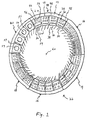
- Figure 1 schematically shows a first embodiment of a brush seal segment 10 of the present invention together with five other similar brush seal segments 12, 14, 16, 18, and 20 all circumferentially arrayed to define an annular brush seal 22.
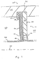
- Figure 2 shows one of the brush seal segments 10 installed in an embodiment of a gas turbine assembly 24 (only a portion of which is shown in Figure 2), such gas turbine assembly 24 having a rotor 26 and a casing 28 radially spaced apart from and circumferentially surrounding the rotor 26, such brush seal segment 10 disposed in the annular gap between the rotor 26 and the casing 28, and such brush seal segment 10 attached to the casing 28.
- the brush seal segment 10 could be disposed in any other rotary machine including, without limitation, a steam turbine.
- a brush seal segment 10 includes a brush-seal back plate 30 having an edge 32, a brush-seal front plate 34 having an edge 36, a plurality of brush-seal bristles 38 each having a free end 40, and a multiplicity of brush-seal damper plates 42, 44, 46, and 48 each having an edge 50 and each having a thickness less than that of the front plate 34.
- the bristles 38 are disposed between the back and damper plates 30 and 42-48, and the damper plates 42-48 are disposed between the bristles 38 and the front plate 34, with the free end 40 of generally each bristle 38 extending beyond the edges 32, 50, and 36 of the back, damper, and front plates 30, 42-48, and 34.
- the damper plates 42-48 proximate their edges 50 are in contact with some of the bristles 38.
- the damper plates 42-48 each have at least one through hole 52.
- the damper plates 42-48 at their edges 50 are in contact with some of the bristles 38.
- the damper plates 42-48 are in contact with generally all of the front-most ones of the bristles 38 (i.e., those bristles 38 closest to the front plate 34).
- the damper plates 42-48 overlap a portion of the front-most ones of the bristles 38, wherein the damper plates 42-48 contact generally the entire overlapped portion of the front-most ones of the bristles 38.
- the damper plates 42-48 are manually-flexible damper plates 42-48, and in another example, the front plate 34 is a manually-rigid front plate 34.
- damper plates 42-48 each can be flexed by hand by an adult person of average strength.
- manufactured is meant that the front plate 34 cannot be flexed by hand by an adult person of average strength.
- the at-least-one through hole 52 is an array of through holes 52
- the damper plates 42-48 include a first damper plate 42.
- the through holes 52 of the first damper plate 42 include a first subset of generally identical holes 54 disposed at a generally identical first distance from the edge 50 of the first damper plate 42.
- the through holes 52 of the first damper plate 42 also include a second subset of generally identical holes 56 disposed at a generally identical second distance from the edge 50 of the first damper plate 42.
- the first distance is less than the second distance.
- the second subset of holes 56 has a fewer number of holes than does the first subset of holes 54, and the holes 54 of the first subset have a smaller total area than the holes 56 of the second subset.
- the damper plates 42-48 of the brush seal segment 10 generally lie in a plane, and the through holes 52 are aligned generally perpendicular to the plane.
- the five other similar brush seal segments 12-20 are shown in Figure 1 with damper plates having different shaped holes, but, in many applications (not shown), the other brush seal segments 12-20 are identical to the brush seal segment 10.
- the brush seal segments 10-20 are identical to brush seal segment 20 which has its damper plates 57 each having a single through hole 59 which simplifies manufacture.
- the through holes 52 can have any shape including, without limitation, round, oval, rectangular, and/or square. It is further noted that, in an array of through holes, the through holes of any damper plate need not be aligned in circumferential rows and/or radial columns.
- a brush seal segment 10 contains many more bristles 38 than are shown in Figure 1. It is also noted that some front plates have a portion (not shown) which extends towards the edge 50 of the damper plates 42-48 and which is spaced apart from the damper plates 42-48. Typically, as seen in Figure 2, the front plate 34 extends the least (of the front, damper, and back plates) towards the free ends 40 of the bristles 38, and the back plate 30 extends the most (of the front, damper, and back plates) towards the free ends 40 of the bristles 38. In one construction, the damper plates 42-48 have a generally rectangular shape, consist essentially of a cobalt-based alloy, and are generally five-thousandths of an inch thick.
- a brush seal segment 10 includes a brush-seal holder 58 having a shape of generally an annular segment of a circular ring, wherein the ring has a longitudinal axis 60.
- the brush-seal holder 58 has an annular brush-seal back plate 30 and an annular brush-seal front plate 34 each generally coaxially aligned with the axis 50 and each having an inner circumferential edge 32 and 36 generally facing the axis 50.
- the brush seal segment 10 also includes a plurality of brush-seal bristles 38 each having a free end 40.
- the brush seal segment 10 further includes a multiplicity of brush-seal damper plates 42-48 each having a radially-innermost edge 36 and each having a thickness less than that of the front plate 34.
- the bristles 38 are disposed longitudinally between the back and damper plates 30 and 42-48, the damper plates 42-48 are circumferentially spaced apart, and the damper plates 42-48 are disposed longitudinally between the bristles 38 and the front plate 34, with the free end 40 of generally each bristle 38 extending beyond the edges 32, 50, and 36 of the back, damper, and front plates 30, 42-48, and 34.
- the damper plates 42-48 proximate their edges 50 are in contact with some of the bristles 38.
- the damper plates 42-48 each have an array of through holes 52.
- the damper plates 42-48 at their edges 50 are in contact with some of the bristles 38.
- the damper plates 42-48 are in contact with generally all of the front-most ones of the bristles 38 (i.e., those bristles 38 closest to the front plate 34).
- the damper plates 42-48 overlap a portion of the front-most ones of the bristles 38, wherein the damper plates 42-48 contact generally the entire overlapped portion of the front-most ones of the bristles 38.
- the damper plates 42-48 are manually-flexible damper plates 42-48, and in another example, the front plate 34 is a manually-rigid front plate 34.
- the at-least-one through hole 52 is an array of through holes 52
- the damper plates 42-48 include a first damper plate 42.
- the through holes 52 of the first damper plate 42 include a first subset of generally identical holes 54 disposed at a generally identical first distance from the edge 50 of the first damper plate 42.
- the through holes 52 of the first damper plate 42 also include a second subset of generally identical holes 56 disposed at a generally identical second distance from the edge 50 of the first damper plate 42.
- the first distance is less than the second distance.
- the second subset of holes 56 has a fewer number of holes than does the first subset of holes 54, and the holes 54 of the first subset have a smaller total area than the. holes 56 of the second subset.
- the through holes 52 are aligned generally parallel to the axis 60.
- a brush seal segment 110 includes a brush-seal back plate 130 having an edge 132, a brush-seal front plate 134 having an edge 136, a plurality of brush-seal bristles 138 each having a free end 140, and at least one wire screen 142, 144, 146, and 148 having an edge 150 and having a thickness less than that of the front plate 134.
- the bristles 138 are disposed between the back plate 130 and the at-least-one wire screen 142-148, and the at-least-one wire screen 142-148 is disposed between the bristles 138 and the front plate 134, with the free end 140 of generally each bristle 138 extending beyond the edge 150 of the at-least-one wire screen 142-148 and beyond the edges 132 and 136 of the back and front plates 130 and 134.
- the at-least-one wire screen 142-148 proximate its edge 150 is in contact with some of the bristles 138. It is noted that the at-least-one wire screen 142-148 has openings 152 between the screen wires.
- the at-least-one wire screen 142-148 at its edge 150 is in contact with some of the bristles 138.
- the at-least-one wire screen 142-148 is in contact with generally all of the front-most ones of the bristles 138 (i.e., those bristles 138 closest to the front plate 134).
- the at-least-one wire screen 142-148 overlaps a portion of the front-most ones of the bristles 138, wherein the at-least-one wire screen 142-148 contacts generally the entire overlapped portion of the front-most ones of the bristles 138.
- the at-least-one wire screen 142-148 is a manually-flexible at-least-one wire screen 142-148
- the front plate 134 is a manually-rigid front plate 134.
- the at-least-one wire screen 142-148 includes adjacent first and second wire screens 142 and 144, wherein the edges 150 of the first and second wire screens 142 and 144 are generally aligned with each other.
- the at-least-one wire screen 142-148 is at least one woven-wire screen 142-148 having a first group of generally parallel wires 154 and a second group of generally parallel wires 156. The wires 156 of the second group are aligned generally perpendicular to the wires 154 of the first group, and the wires 154 of the first group are aligned at a generally forty-five degree angle with the edge 150 of the at-least-one wire screen 142-148. This minimizes wire loss should the edge 150 become worn.
- the at-least-one wire screen 142-148 typically would contain more wires 154 and 156 than those shown in Figure 3.
- the at-least-one wire screen 142-148 has a generally rectangular shape, and the wires 154 and 156 consist essentially of a cobalt-based alloy and have a diameter between generally five and ten thousandths of an inch.
- the five other similar brush seal segments 112-120 are shown in Figure 1 with wire screens having different wire arrangements, but, in many applications (not shown), the other brush seal segments 112-120 are identical to the brush seal segment 110.
- a brush seal segment 110 contains many more bristles 138 than are shown in Figure 3. It is also noted that some front plates have a portion (not shown) which extends towards the edge 150 of the at-least-one wire screen 142-148 and which is spaced apart from the at-least-one wire screen 142-148. Typically, as seen in Figure 4, the front plate 134 extends the least (of the at-least-one wire screen and the front and back plates) towards the free ends 140 of the bristles 138, and the back plate 130 extends the most (of the at-least-one wire screen and the front and back plates) towards the free ends 140 of the bristles 138.
- a brush seal segment 110 includes a brush-seal holder 158 having a shape of generally an annular segment of a circular ring, wherein the ring has a longitudinal axis 160.
- the brush-seal holder 158 has an annular brush-seal back plate 130 and an annular brush-seal front plate 134 each generally coaxially aligned with the axis 150 and each having an inner circumferential edge 132 and 136 generally facing the axis 50.
- the brush seal segment 110 also includes a plurality of brush-seal bristles 138 each having a free end 140.
- the brush seal segment 110 further includes at least one wire screen 142-148 having a radially-innermost edge 136 and having a thickness less than that of the front plate 134.
- the bristles 138 are disposed longitudinally between the back plate 130 and the at-least-one wire screen 142-148, the at-least-one wire screen 142-148 is circumferentially spaced apart, and the at-least-one wire screen 142-148 is disposed longitudinally between the bristles 138 and the front plate 134, with the free end 140 of generally each bristle 138 extending beyond the edge 150 of the at-least-one wire screen 142-148 and beyond the edges 132 and 136 of the back and front plates 130 and 134.
- the at-least-one wire screen 142-148 proximate its edge 150 is in contact with some of the bristles 138.
- the at-least-one wire screen 142-148 at its edge 150 is in contact with some of the bristles 138.
- the at-least-one wire screen 142-148 is in contact with generally all of the front-most ones of the bristles 138 (i.e., those bristles 138 closest to the front plate 134).
- the at-least-one wire screen 142-148 overlaps a portion of the front-most ones of the bristles 138, wherein the at-least-one wire screen 142-148 contacts generally the entire overlapped portion of the front-most ones of the bristles 138.
- the at-least-one wire screen 142-148 is a manually-flexible at-least-one wire screen 142-148
- the front plate 134 is a manually-rigid front plate 134.
- the at-least-one wire screen 142-148 includes adjacent first and second wire screens 142 and 144, wherein the edges 150 of the first and second wire screens 142 and 144 are generally aligned with each other.
- the at-least-one wire screen 142-148 is at least one woven-wire screen 142-148 having a first group of generally parallel wires 154 and a second group of generally parallel wires 156. The wires 156 of the second group are aligned generally perpendicular to the wires 154 of the first group, and the wires 154 of the first group are aligned at a generally forty-five degree angle with the edge 150 of the at-least-one wire screen 142-148.
- the bristles 38 and 138 are each canted at a generally-identical angle with respect to a corresponding radius line (not shown) extending outward (from the axis 60 and 160) to each of the bristles 38 and 138.
- the angle of the bristles 38 and 138 is generally forty-five degrees.
- the back plate 30 and 130 and the front plate 34 and 134 each are of monolithic construction and consist essentially of metal or metal alloy such as, but not limited to, stainless steel.
- the bristles 38 and 138 typically consist essentially of metal-wire or ceramic-wire bristles such as, but not limited to, cobalt-based-alloy wire bristles.
- metal-wire bristles 38 and 138 are attached to the brush-seal holder 58 and 158 by welding (such weldment omitted from the figures for clarity).
- the brush seal segment 10 and 110 has a high-pressure side 62 and 162 and a low-pressure side 64 and 164, with the radially-outward part of the brush-seal holder 58 and 158 attached to the casing 28 and 128 (such as by engagement of the brush seal segment 10 and 110 with a slot 66 and 166 in the casing 28 and 128), and with the inwardly-projecting free ends 40 and 140 (as seen in the view of Figures 2 and 4) of the bristles 38 and 138 disposed proximate (and in one application disposed as to just touch) the rotor 26 and 126.
- the back plate 30 and 130 is a downstream plate, and the front plate 34 and 134 is an upstream plate.
- Gas flow is from the high-pressure side 62 and 162 of the brush seal segment 10 and 110 to the low-pressure side 64 and 164 of the brush seal segment 10 and 110.
- the brush seal segment 10 and 110 is an annular segment of a circular ring having a longitudinal axis 60 and 160. It is herein pointed out that, for the purpose of illustration, the circular ring may be considered to be the annular brush seal 22 and 122 shown in Figures 1 and 3.
- the damper plates (or the at-least-one wire screen) are in contact with some of the bristles thus providing dampening to the bristles in turbulent flow.
- the at-least-one through hole in each of the damper plates (or the openings in the at-least-one wire screen) allow a subflow to pass therethrough and purge the space between the damper plates (or the at-least-one wire screen) and the bristles of turbulent flow otherwise entering that space near the free ends of the bristles such that the free ends of the bristles remain damped since they experience a more stable flow resulting in less bristle flutter and hence increased brush-seal wear
Landscapes
- Engineering & Computer Science (AREA)
- General Engineering & Computer Science (AREA)
- Mechanical Engineering (AREA)
- Turbine Rotor Nozzle Sealing (AREA)
- Sealing Devices (AREA)
Applications Claiming Priority (4)
| Application Number | Priority Date | Filing Date | Title |
|---|---|---|---|
| US13418599P | 1999-05-13 | 1999-05-13 | |
| US134185P | 1999-05-13 | ||
| US46095799A | 1999-12-14 | 1999-12-14 | |
| US460957 | 1999-12-14 |
Publications (2)
| Publication Number | Publication Date |
|---|---|
| EP1052438A2 true EP1052438A2 (de) | 2000-11-15 |
| EP1052438A3 EP1052438A3 (de) | 2002-02-06 |
Family
ID=26832058
Family Applications (1)
| Application Number | Title | Priority Date | Filing Date |
|---|---|---|---|
| EP00304027A Withdrawn EP1052438A3 (de) | 1999-05-13 | 2000-05-12 | Bürstendichtungssegment mit Dämpfung der Borsten |
Country Status (2)
| Country | Link |
|---|---|
| EP (1) | EP1052438A3 (de) |
| JP (1) | JP2001073708A (de) |
Cited By (9)
| Publication number | Priority date | Publication date | Assignee | Title |
|---|---|---|---|---|
| EP1239118A3 (de) * | 2001-03-05 | 2004-09-08 | General Electric Company | Flexible Textildichtung für Turbinenbrennkammern |
| US6907207B2 (en) | 2001-08-22 | 2005-06-14 | T & M Corporation | Sealing material for rotary body, usage of the same, and developing apparatus |
| WO2008127244A1 (en) * | 2007-04-16 | 2008-10-23 | Rexnord Industries Llc | Brush seal |
| CN103225519A (zh) * | 2013-04-24 | 2013-07-31 | 石伟伟 | 自调整叶片式汽封 |
| US9598970B2 (en) | 2012-04-08 | 2017-03-21 | Eagle Industry Co., Ltd. | Brush seal |
| EP2586994A3 (de) * | 2011-10-26 | 2017-05-03 | General Electric Company | Metallstatordichtung |
| US9752448B2 (en) | 2012-04-08 | 2017-09-05 | Eagle Industry Co., Ltd. | Brush seal |
| US20180142565A1 (en) * | 2016-11-21 | 2018-05-24 | Pratt & Whitney Canada Corp. | Brush seal assembly and method |
| US9995395B2 (en) | 2012-04-08 | 2018-06-12 | Eagle Industry Co., Ltd. | Brush seal |
Families Citing this family (1)
| Publication number | Priority date | Publication date | Assignee | Title |
|---|---|---|---|---|
| US20120177484A1 (en) * | 2011-01-07 | 2012-07-12 | General Electric Company | Elliptical Sealing System |
Citations (1)
| Publication number | Priority date | Publication date | Assignee | Title |
|---|---|---|---|---|
| US5400952A (en) | 1993-10-25 | 1995-03-28 | General Electric Company | Method and apparatus for damping a brush seal |
Family Cites Families (4)
| Publication number | Priority date | Publication date | Assignee | Title |
|---|---|---|---|---|
| US5568931A (en) * | 1992-08-20 | 1996-10-29 | General Electric Company | Brush seal |
| US5474306A (en) * | 1992-11-19 | 1995-12-12 | General Electric Co. | Woven seal and hybrid cloth-brush seals for turbine applications |
| DE19529655C2 (de) * | 1995-08-11 | 1999-04-22 | Mtu Muenchen Gmbh | Bürstendichtung für Turbomaschinen |
| ATE238509T1 (de) * | 1995-10-05 | 2003-05-15 | Sealol | Bürstendichtung mit einer biegsamen frontscheibe |
-
2000
- 2000-05-12 EP EP00304027A patent/EP1052438A3/de not_active Withdrawn
- 2000-05-12 JP JP2000139499A patent/JP2001073708A/ja not_active Withdrawn
Patent Citations (1)
| Publication number | Priority date | Publication date | Assignee | Title |
|---|---|---|---|---|
| US5400952A (en) | 1993-10-25 | 1995-03-28 | General Electric Company | Method and apparatus for damping a brush seal |
Cited By (10)
| Publication number | Priority date | Publication date | Assignee | Title |
|---|---|---|---|---|
| EP1239118A3 (de) * | 2001-03-05 | 2004-09-08 | General Electric Company | Flexible Textildichtung für Turbinenbrennkammern |
| US6907207B2 (en) | 2001-08-22 | 2005-06-14 | T & M Corporation | Sealing material for rotary body, usage of the same, and developing apparatus |
| WO2008127244A1 (en) * | 2007-04-16 | 2008-10-23 | Rexnord Industries Llc | Brush seal |
| EP2586994A3 (de) * | 2011-10-26 | 2017-05-03 | General Electric Company | Metallstatordichtung |
| US9598970B2 (en) | 2012-04-08 | 2017-03-21 | Eagle Industry Co., Ltd. | Brush seal |
| US9752448B2 (en) | 2012-04-08 | 2017-09-05 | Eagle Industry Co., Ltd. | Brush seal |
| US9995395B2 (en) | 2012-04-08 | 2018-06-12 | Eagle Industry Co., Ltd. | Brush seal |
| CN103225519A (zh) * | 2013-04-24 | 2013-07-31 | 石伟伟 | 自调整叶片式汽封 |
| US20180142565A1 (en) * | 2016-11-21 | 2018-05-24 | Pratt & Whitney Canada Corp. | Brush seal assembly and method |
| US10844741B2 (en) * | 2016-11-21 | 2020-11-24 | Pratt & Whitney Canada Corp. | Brush seal assembly and method |
Also Published As
| Publication number | Publication date |
|---|---|
| EP1052438A3 (de) | 2002-02-06 |
| JP2001073708A (ja) | 2001-03-21 |
Similar Documents
| Publication | Publication Date | Title |
|---|---|---|
| EP1052437B1 (de) | Bürstendichtungssegment mit Dämpfung der Borsten | |
| US6030175A (en) | Hybrid seal and rotary machine containing such hybrid seal | |
| JP5178102B2 (ja) | 単一の弾性プレート部材を使用したシャフトシール | |
| US6105966A (en) | Brush seal segment | |
| US9879555B2 (en) | Turbine combustion system transition seals | |
| US5961280A (en) | Anti-hysteresis brush seal | |
| JP4712936B2 (ja) | 封じ集成体とそれを持つ回転機械 | |
| EP2430297B1 (de) | Turbinenmotor mit strukturbefestigungssystem für übergangskanalauslass | |
| US7604242B2 (en) | Pressure balanced brush seal | |
| US8382120B2 (en) | Method and apparatus for compliant plate seals | |
| US6161836A (en) | Brush seal and rotary machine containing such brush seal | |
| US9587505B2 (en) | L brush seal for turbomachinery application | |
| US5941685A (en) | Brush seal for use on bumpy rotating surfaces | |
| US9322287B2 (en) | Brush seal for turbine | |
| US20090315272A1 (en) | Brush seal device | |
| CN102918308B (zh) | 轴封机构、及具备该机构的旋转机械 | |
| EP1052438A2 (de) | Bürstendichtungssegment mit Dämpfung der Borsten | |
| JPH11201293A (ja) | 回転機械用のラビリンス/ブラシ併合シール | |
| EP1510655B1 (de) | Unterstützung einer Bürstendichtung | |
| US5961125A (en) | Brush seal for use on rough rotating surfaces | |
| US20130154199A1 (en) | Leaf seal | |
| GB2267319A (en) | Sealing components in turbine engines. | |
| EP1108926B1 (de) | Rotationsmaschine mit einer Bürstendichtung | |
| EP1403584B1 (de) | Turbinenfederklammerdichtung | |
| US11702991B2 (en) | Turbomachine sealing arrangement having a heat shield |
Legal Events
| Date | Code | Title | Description |
|---|---|---|---|
| PUAI | Public reference made under article 153(3) epc to a published international application that has entered the european phase |
Free format text: ORIGINAL CODE: 0009012 |
|
| AK | Designated contracting states |
Kind code of ref document: A2 Designated state(s): DE FR GB Kind code of ref document: A2 Designated state(s): AT BE CH CY DE DK ES FI FR GB GR IE IT LI LU MC NL PT SE |
|
| AX | Request for extension of the european patent |
Free format text: AL;LT;LV;MK;RO;SI |
|
| PUAL | Search report despatched |
Free format text: ORIGINAL CODE: 0009013 |
|
| AK | Designated contracting states |
Kind code of ref document: A3 Designated state(s): AT BE CH CY DE DK ES FI FR GB GR IE IT LI LU MC NL PT SE |
|
| AX | Request for extension of the european patent |
Free format text: AL;LT;LV;MK;RO;SI |
|
| 17P | Request for examination filed |
Effective date: 20020806 |
|
| AKX | Designation fees paid |
Free format text: DE FR GB |
|
| 17Q | First examination report despatched |
Effective date: 20020927 |
|
| STAA | Information on the status of an ep patent application or granted ep patent |
Free format text: STATUS: THE APPLICATION IS DEEMED TO BE WITHDRAWN |
|
| 18D | Application deemed to be withdrawn |
Effective date: 20030208 |