EP1052760A2 - Système d'un CAN-bus avec des sous-réseaux déconnectables automatiquement pendant des pannes - Google Patents
Système d'un CAN-bus avec des sous-réseaux déconnectables automatiquement pendant des pannes Download PDFInfo
- Publication number
- EP1052760A2 EP1052760A2 EP00250141A EP00250141A EP1052760A2 EP 1052760 A2 EP1052760 A2 EP 1052760A2 EP 00250141 A EP00250141 A EP 00250141A EP 00250141 A EP00250141 A EP 00250141A EP 1052760 A2 EP1052760 A2 EP 1052760A2
- Authority
- EP
- European Patent Office
- Prior art keywords
- network
- subnetworks
- monitoring device
- bus system
- sub
- Prior art date
- Legal status (The legal status is an assumption and is not a legal conclusion. Google has not performed a legal analysis and makes no representation as to the accuracy of the status listed.)
- Withdrawn
Links
Images
Classifications
-
- H—ELECTRICITY
- H04—ELECTRIC COMMUNICATION TECHNIQUE
- H04L—TRANSMISSION OF DIGITAL INFORMATION, e.g. TELEGRAPHIC COMMUNICATION
- H04L12/00—Data switching networks
- H04L12/28—Data switching networks characterised by path configuration, e.g. LAN [Local Area Networks] or WAN [Wide Area Networks]
- H04L12/40—Bus networks
- H04L12/40006—Architecture of a communication node
-
- H—ELECTRICITY
- H04—ELECTRIC COMMUNICATION TECHNIQUE
- H04L—TRANSMISSION OF DIGITAL INFORMATION, e.g. TELEGRAPHIC COMMUNICATION
- H04L12/00—Data switching networks
- H04L12/28—Data switching networks characterised by path configuration, e.g. LAN [Local Area Networks] or WAN [Wide Area Networks]
- H04L12/46—Interconnection of networks
-
- H—ELECTRICITY
- H04—ELECTRIC COMMUNICATION TECHNIQUE
- H04L—TRANSMISSION OF DIGITAL INFORMATION, e.g. TELEGRAPHIC COMMUNICATION
- H04L69/00—Network arrangements, protocols or services independent of the application payload and not provided for in the other groups of this subclass
- H04L69/40—Network arrangements, protocols or services independent of the application payload and not provided for in the other groups of this subclass for recovering from a failure of a protocol instance or entity, e.g. service redundancy protocols, protocol state redundancy or protocol service redirection
-
- H—ELECTRICITY
- H04—ELECTRIC COMMUNICATION TECHNIQUE
- H04L—TRANSMISSION OF DIGITAL INFORMATION, e.g. TELEGRAPHIC COMMUNICATION
- H04L12/00—Data switching networks
- H04L12/28—Data switching networks characterised by path configuration, e.g. LAN [Local Area Networks] or WAN [Wide Area Networks]
- H04L12/40—Bus networks
- H04L2012/40208—Bus networks characterized by the use of a particular bus standard
- H04L2012/40215—Controller Area Network CAN
-
- H—ELECTRICITY
- H04—ELECTRIC COMMUNICATION TECHNIQUE
- H04L—TRANSMISSION OF DIGITAL INFORMATION, e.g. TELEGRAPHIC COMMUNICATION
- H04L12/00—Data switching networks
- H04L12/28—Data switching networks characterised by path configuration, e.g. LAN [Local Area Networks] or WAN [Wide Area Networks]
- H04L12/40—Bus networks
- H04L2012/40267—Bus for use in transportation systems
- H04L2012/40273—Bus for use in transportation systems the transportation system being a vehicle
Definitions
- the invention relates to a CAN bus system for a motor vehicle with one in several Subnetwork structured CAN network.
- CAN bus system controller area network
- the CAN bus system comprises a bus line connecting several CAN nodes, which consists of two parallel lines CAN-Low and CAN-High is formed.
- the CAN bus system is generally relatively insensitive to interference on one of the two lines CAN-Low or CAN-High, the interference in Form of an interruption, a short circuit to ground or a short circuit against supply voltage can occur.
- faults occur on both lines, so data traffic is no longer possible because of the access procedure of the CAN bus system requires that the CAN low and CAN high connections all CAN nodes are galvanically connected to each other. Such Faults can be caused in particular by an accident.
- US Pat. No. 5,818,673 is a power distribution system for a motor vehicle known that a variety of power distribution sections for power supply electrical loads.
- the power supply sections are each via electrical lines with electricity from an alternator and a battery supply device supplies and conduct the electricity via electrical branch lines to the electrical loads.
- the power supply sections are equipped with a variety of current detectors to detect the Stroms in the electrical lines and branch lines, with several switches to interrupt the connection between the electrical lines and Branch lines on the one hand and the electrical loads on the other hand and with one Control unit for controlling the switch provided, the control unit with connected to the current detectors and when an abnormal current value occurs in one of the electrical lines or branch lines Disconnects the line from the rest of the power distribution system.
- This well known System can cause malfunction of all electrical components in the event prevent a fault caused by an accident.
- the system is however relatively complex and correspondingly expensive.
- the object of the present invention is to provide a CAN bus system to create the type mentioned, which in the event of a fault, in particular in the case a short circuit caused by an accident, at least partially functional remains, this task being accomplished in a relatively inexpensive manner shall be.
- each subnet has a switch by which it can be disconnected from the rest of the CAN network a common monitoring device is assigned to the subnets communication, which is connected to all subnetworks via a transceiver monitored on the subnets and if a fault occurs in one the subnetworks the subnetwork which has the fault by means of this subnetwork disconnected assigned switch from the rest of the CAN network.
- the solution according to the invention is characterized in that a generic CAN bus system supplemented with just a few additional components and is therefore improved in a comparatively cost-effective manner in that that when a malfunction occurs, an automatic separation of the from the malfunction affected power supply and thus the functionality of the rest CAN network remains intact. It is also advantageous that in normal operation of the CAN bus systems according to the invention require no additional computing power becomes.
- the monitoring device of the CAN bus system according to the invention can preferably have a bus controller in the form of a microcontroller.
- the monitoring device if a malfunction occurs, switch off the subnets one after the other and one or more test messages each via the rest of the CAN network sends, the continuation of the shutdown process is ended and that Subnet currently switched off remains disconnected as soon as the monitoring device determines that the test message or test messages are correct have been sent and received.
- An alternative embodiment of the CAN bus system according to the invention is characterized in that the monitoring device when a Fault switches off all subnets and tests the subnets one after the other, after the test of all subnetworks have been completed, the switches of those subnetworks be closed again, in which no malfunction was found.
- switches of the subnets each have a relay and two switching contacts, one of which Switch contact in the CAN low line and the other switch contact in the CAN high line of the subnetwork is arranged, and wherein the relay via a Control line is connected to the monitoring device.
- the CAN network can preferably be divided into four subnets To be arranged.
- This configuration enables four areas of the To differentiate the motor vehicle from one another, preferably the areas at the front left, front right, rear left and rear right, so that in a unilateral rear-end collision if applicable, the areas not affected by this electrical components of the motor vehicle continue to function stay.
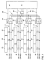
- the schematically shown CAN bus system comprises one of two in parallel Lines CAN low and CAN high formed bidirectional bus line 1, from the go off four branches 2, 3, 4 and 5.
- Each branch defines a subnet, whereby the first subnet 20 the front left area of the motor vehicle, the second Subnet 30 the front right area of the motor vehicle, the third subnet 40 the rear left area of the motor vehicle and the fourth subnet 50 is assigned to the rear right area of the motor vehicle.
- Any subnet has several connection points, so-called CAN nodes 21, 22, 23; 31, 32, 33; 41, 42, 43; 51, 52, 53 on the various vehicle lights such as the Flashing light, the low beam, the high beam, the parking light, the tail light, the Brake lights, etc. are assigned.
- each of the subnetworks 20, 30, 40, 50 has a switch 24, 34, 44 or 54, through which it can be separated from the rest of the CAN network can. In the normal state, all switches 24, 34, 44, 54 are closed.
- the Switches are designed so that bidirectional data traffic is possible when a switch is opened, both lines of the respective sub-network 20, 30, 40 or 50 are separated.
- the switches 24, 34, 44, 54 from a relay and two switch contacts, the one switch contact in the CAN low line and the other switch contact in the CAN high line of the respective subnetwork 20, 30, 40 or 50 is arranged.
- the relay of each switch is connected to a control line 25, 35, 45 or 55
- Monitoring device 6 connected to a bus controller in the form of a Has microcontroller and a transceiver 7 with the CAN low line and the CAN high line of bus line 1 is connected.
- a bus controller in the form of a Has microcontroller and a transceiver 7 with the CAN low line and the CAN high line of bus line 1 is connected.
- the bus controller monitors the communication on the CAN bus and its Subnets 20, 30, 40, 50. Is the communication disrupted, for example because of an accident in one of the subnets 20, 30, 40, 50 or in one of the CAN nodes 21, 22, 23; 31, 32, 33; 41, 42, 43; 51, 52, 53 a short to ground or is present against supply voltage, this fault is resolved by Bus controller of the monitoring device 6 detects and the relevant subnet automatically disconnected from the rest of the CAN network using the assigned switch. The shutdown is preferably carried out in such a way that the monitoring device 6 the subnets one after the other when a fault is detected 20, 30, 40, 50 switches off and sends test messages via the rest of the CAN network. If these test messages can be sent and received correctly, then the subnet currently disconnected is the faulty one. This subnet remains then disconnected from the rest of the CAN network, while data traffic over the intact rest of the CAN network can continue to run.
- a faulty subnet can also be switched off in this way take place that the monitoring device 6 all upon detection of a fault Subnets 20, 30, 40, 50 switches off and then the subnets one after the other tests, the switches after completion of the test of all subnets 20, 30, 40, 50 those subnets are closed again, in which no fault is found has been.
Landscapes
- Engineering & Computer Science (AREA)
- Computer Networks & Wireless Communication (AREA)
- Signal Processing (AREA)
- Small-Scale Networks (AREA)
- Computer Security & Cryptography (AREA)
Applications Claiming Priority (2)
| Application Number | Priority Date | Filing Date | Title |
|---|---|---|---|
| DE19922408 | 1999-05-14 | ||
| DE19922408A DE19922408B4 (de) | 1999-05-14 | 1999-05-14 | Bus-System mit bei Störungen automatisch abschaltbaren Teilnetzen |
Publications (2)
| Publication Number | Publication Date |
|---|---|
| EP1052760A2 true EP1052760A2 (fr) | 2000-11-15 |
| EP1052760A3 EP1052760A3 (fr) | 2001-04-11 |
Family
ID=7908171
Family Applications (1)
| Application Number | Title | Priority Date | Filing Date |
|---|---|---|---|
| EP00250141A Withdrawn EP1052760A3 (fr) | 1999-05-14 | 2000-05-11 | Système d'un CAN-bus avec des sous-réseaux déconnectables automatiquement pendant des pannes |
Country Status (2)
| Country | Link |
|---|---|
| EP (1) | EP1052760A3 (fr) |
| DE (1) | DE19922408B4 (fr) |
Cited By (8)
| Publication number | Priority date | Publication date | Assignee | Title |
|---|---|---|---|---|
| EP1109348A3 (fr) * | 1999-12-16 | 2004-09-15 | TRW Automotive Electronics & Components GmbH & Co. KG | Unité de découplage pour système de bus |
| EP1482676A2 (fr) | 2003-05-28 | 2004-12-01 | KNORR-BREMSE SYSTEME FÜR NUTZFAHRZEUGE GmbH | Système d'un CAN-bus |
| US7242109B2 (en) | 2000-11-30 | 2007-07-10 | John Deere Fabriek Horst B.V. | Bus system for an agricultural vehicle |
| CN100565230C (zh) * | 2007-07-20 | 2009-12-02 | 山东省科学院自动化研究所 | Can总线断路检测电路及其方法 |
| CN102148860A (zh) * | 2011-01-25 | 2011-08-10 | 山东天海电装有限公司 | 一种汽车智能网络 |
| AT510121A1 (de) * | 2010-06-23 | 2012-01-15 | Roman Obermaisser | Sternkoppler für controller area network (can) |
| CN110213114A (zh) * | 2019-06-21 | 2019-09-06 | 深圳前海微众银行股份有限公司 | 去中心化的网络服务方法、装置、设备及可读存储介质 |
| DE102021112121A1 (de) | 2021-05-10 | 2022-11-10 | Schaeffler Technologies AG & Co. KG | Verfahren zur Datenübertragung innerhalb eines Fahrzeugkontrollsystems, Kontrollsystem und Kraftfahrzeug |
Families Citing this family (4)
| Publication number | Priority date | Publication date | Assignee | Title |
|---|---|---|---|---|
| DE102006013329B4 (de) * | 2006-03-21 | 2008-01-31 | Yazaki Europe Ltd., Hemel Hempstead | Verfahren zur Fehlererkennung eines Netzwerksystems |
| DE102012221787A1 (de) * | 2012-11-28 | 2014-05-28 | Siemens Aktiengesellschaft | Verfahren zum Prüfen der Betriebsbereitschaft und zugehörige Einheit |
| DE102012221882A1 (de) * | 2012-11-29 | 2014-06-05 | Siemens Aktiengesellschaft | Verfahren zum Prüfen der Betriebsbereitschaft, zugehörige Einheit und zugehörige Vorrichtung |
| US12298758B2 (en) * | 2023-10-20 | 2025-05-13 | Caterpillar Underground Mining Pty Ltd. | Systems and methods for operating a controller area network |
Citations (1)
| Publication number | Priority date | Publication date | Assignee | Title |
|---|---|---|---|---|
| WO1998030961A1 (fr) | 1996-12-23 | 1998-07-16 | N O B Elektronik Ab | Systeme electronique a bus |
Family Cites Families (5)
| Publication number | Priority date | Publication date | Assignee | Title |
|---|---|---|---|---|
| DE4226704A1 (de) * | 1992-08-12 | 1994-02-17 | Becker Autoradio | Verfahren zum Betreiben einer Anlage mit mehreren an ein Bus-System angeschlossenen Komponenten und Schnittstellen-Schaltungsanordnung zur Durchführung des Verfahrens |
| DE19509133C2 (de) * | 1994-04-11 | 2003-07-17 | Daimler Chrysler Ag | Anordnung zur Überwachung von Zweidraht-Busleitungen |
| DE4429953B4 (de) * | 1994-08-24 | 2012-06-06 | Wabco Gmbh | Serielles Bussystem |
| JPH09275632A (ja) * | 1996-04-04 | 1997-10-21 | Harness Sogo Gijutsu Kenkyusho:Kk | 電力分配システム |
| DE29702480U1 (de) * | 1997-02-13 | 1998-07-02 | Diehl Stiftung & Co., 90478 Nürnberg | Bus-Verknüpfungsmodul |
-
1999
- 1999-05-14 DE DE19922408A patent/DE19922408B4/de not_active Expired - Lifetime
-
2000
- 2000-05-11 EP EP00250141A patent/EP1052760A3/fr not_active Withdrawn
Patent Citations (1)
| Publication number | Priority date | Publication date | Assignee | Title |
|---|---|---|---|---|
| WO1998030961A1 (fr) | 1996-12-23 | 1998-07-16 | N O B Elektronik Ab | Systeme electronique a bus |
Cited By (11)
| Publication number | Priority date | Publication date | Assignee | Title |
|---|---|---|---|---|
| EP1109348A3 (fr) * | 1999-12-16 | 2004-09-15 | TRW Automotive Electronics & Components GmbH & Co. KG | Unité de découplage pour système de bus |
| US6996649B2 (en) | 1999-12-16 | 2006-02-07 | Trw Automotive Electronics & Components Gmbh & Co.Kg | Decoupling unit for bus systems that blocks abnormal dominant signals from passing between connected bus systems |
| US7242109B2 (en) | 2000-11-30 | 2007-07-10 | John Deere Fabriek Horst B.V. | Bus system for an agricultural vehicle |
| EP1482676A2 (fr) | 2003-05-28 | 2004-12-01 | KNORR-BREMSE SYSTEME FÜR NUTZFAHRZEUGE GmbH | Système d'un CAN-bus |
| EP1482676A3 (fr) * | 2003-05-28 | 2006-05-10 | KNORR-BREMSE SYSTEME FÜR NUTZFAHRZEUGE GmbH | Système d'un CAN-bus |
| CN100565230C (zh) * | 2007-07-20 | 2009-12-02 | 山东省科学院自动化研究所 | Can总线断路检测电路及其方法 |
| AT510121A1 (de) * | 2010-06-23 | 2012-01-15 | Roman Obermaisser | Sternkoppler für controller area network (can) |
| CN102148860A (zh) * | 2011-01-25 | 2011-08-10 | 山东天海电装有限公司 | 一种汽车智能网络 |
| CN110213114A (zh) * | 2019-06-21 | 2019-09-06 | 深圳前海微众银行股份有限公司 | 去中心化的网络服务方法、装置、设备及可读存储介质 |
| CN110213114B (zh) * | 2019-06-21 | 2024-04-09 | 深圳前海微众银行股份有限公司 | 去中心化的网络服务方法、装置、设备及可读存储介质 |
| DE102021112121A1 (de) | 2021-05-10 | 2022-11-10 | Schaeffler Technologies AG & Co. KG | Verfahren zur Datenübertragung innerhalb eines Fahrzeugkontrollsystems, Kontrollsystem und Kraftfahrzeug |
Also Published As
| Publication number | Publication date |
|---|---|
| EP1052760A3 (fr) | 2001-04-11 |
| DE19922408A1 (de) | 2000-11-16 |
| DE19922408B4 (de) | 2010-05-20 |
Similar Documents
| Publication | Publication Date | Title |
|---|---|---|
| DE19854953C1 (de) | Batteriebordnetz mit Sicherheitsabschaltung | |
| DE112017002159B4 (de) | Schaltvorrichtung für ein Bordnetz, sowie Bordnetzsystem | |
| DE69726213T2 (de) | Elektrisches Energieverteilungssystem | |
| DE69228780T2 (de) | Kraftfahrzeug-Multiplexübertragungsgerät | |
| EP3022432B1 (fr) | Coupe-circuit électronique de sécurité pour véhicules à moteur | |
| EP4084249B1 (fr) | Réseau embarqué; en particulier pour un véhicule automobile | |
| DE102008010979A1 (de) | Bordnetz für ein Kraftfahrzeug | |
| DE19921451C1 (de) | Bordnetz bei Kraftfahrzeugen | |
| DE19811626A1 (de) | Stromversorgungsanlage für Fahrzeug | |
| WO2016075106A1 (fr) | Réseau d'alimentation de vehicule automobile | |
| EP3934941A1 (fr) | Réseau d'énergie pour un véhicule à moteur et procédé de fonctionnement d'un réseau d'énergie pour un véhicule à moteur | |
| EP4373714A1 (fr) | Réseau de bord et procédé pour le faire fonctionner | |
| DE4424471C2 (de) | Elektrisches Anhängeranschlußgerät für ein Zugfahrzeug | |
| EP3022433A1 (fr) | Montage de contacteur dans un circuit de bord de véhicule à moteur | |
| DE19922408B4 (de) | Bus-System mit bei Störungen automatisch abschaltbaren Teilnetzen | |
| DE102012022083B4 (de) | Elektrisches Versorgungsnetz für ein Kraftfahrzeug | |
| DE60126843T2 (de) | System und verfahren zum schutz gegen kurzschlüsse in elektrischen leistungsverteilungsarchitekturen mit zwei spannungspegeln | |
| EP4373713A1 (fr) | Dispositif de distribution de courant et véhicule automobile | |
| DE10317362B4 (de) | Fahrzeugbordnetz und Verfahren zum Betreiben eines Fahrzeugbordnetzes | |
| DE102014221281A1 (de) | Fahrzeug-Bordnetz mit hoher Verfügbarkeit | |
| WO2014023375A1 (fr) | Véhicule automobile équipé d'une alimentation à basse tension de grande sécurité | |
| DE102005036174A1 (de) | Vorrichtung und Verfahren zur Auslösung von Batterieabtrennungen in Kraftfahrzeugen | |
| DE19813964A1 (de) | Bussystem mit einer Zentraleinheit eine Mehrzahl von Steuermodulen, insbesondere für Insassenschutzsysteme in Kraftfahrzeugen | |
| DE102020120410B3 (de) | Verfahren zum Betreiben eines Bordnetzes, Bordnetz sowie Kraftfahrzeug mit einem Bordnetz | |
| DE10258899A1 (de) | Kraftfahrzeuge mit einer elektrischen Anlage |
Legal Events
| Date | Code | Title | Description |
|---|---|---|---|
| PUAI | Public reference made under article 153(3) epc to a published international application that has entered the european phase |
Free format text: ORIGINAL CODE: 0009012 |
|
| AK | Designated contracting states |
Kind code of ref document: A2 Designated state(s): AT BE CH CY DE DK ES FI FR GB GR IE IT LI LU MC NL PT SE |
|
| AX | Request for extension of the european patent |
Free format text: AL;LT;LV;MK;RO;SI |
|
| PUAL | Search report despatched |
Free format text: ORIGINAL CODE: 0009013 |
|
| RIC1 | Information provided on ipc code assigned before grant |
Free format text: 7H 02J 13/00 A, 7H 04L 12/28 B, 7B 60R 16/02 B, 7G 06F 13/40 B |
|
| AK | Designated contracting states |
Kind code of ref document: A3 Designated state(s): AT BE CH CY DE DK ES FI FR GB GR IE IT LI LU MC NL PT SE |
|
| AX | Request for extension of the european patent |
Free format text: AL;LT;LV;MK;RO;SI |
|
| 17P | Request for examination filed |
Effective date: 20011011 |
|
| AKX | Designation fees paid |
Free format text: AT BE CH CY DE DK ES FI FR GB GR IE IT LI LU MC NL PT SE |
|
| 17Q | First examination report despatched |
Effective date: 20071213 |
|
| GRAP | Despatch of communication of intention to grant a patent |
Free format text: ORIGINAL CODE: EPIDOSNIGR1 |
|
| STAA | Information on the status of an ep patent application or granted ep patent |
Free format text: STATUS: THE APPLICATION IS DEEMED TO BE WITHDRAWN |
|
| 18D | Application deemed to be withdrawn |
Effective date: 20100213 |