EP1052767A2 - Moteur à commutation électrique - Google Patents
Moteur à commutation électrique Download PDFInfo
- Publication number
- EP1052767A2 EP1052767A2 EP00109534A EP00109534A EP1052767A2 EP 1052767 A2 EP1052767 A2 EP 1052767A2 EP 00109534 A EP00109534 A EP 00109534A EP 00109534 A EP00109534 A EP 00109534A EP 1052767 A2 EP1052767 A2 EP 1052767A2
- Authority
- EP
- European Patent Office
- Prior art keywords
- phase
- motor
- positioning
- excitation windings
- excitation
- Prior art date
- Legal status (The legal status is an assumption and is not a legal conclusion. Google has not performed a legal analysis and makes no representation as to the accuracy of the status listed.)
- Withdrawn
Links
Images

Classifications
-
- H—ELECTRICITY
- H02—GENERATION; CONVERSION OR DISTRIBUTION OF ELECTRIC POWER
- H02P—CONTROL OR REGULATION OF ELECTRIC MOTORS, ELECTRIC GENERATORS OR DYNAMO-ELECTRIC CONVERTERS; CONTROLLING TRANSFORMERS, REACTORS OR CHOKE COILS
- H02P6/00—Arrangements for controlling synchronous motors or other dynamo-electric motors using electronic commutation dependent on the rotor position; Electronic commutators therefor
- H02P6/20—Arrangements for starting
- H02P6/22—Arrangements for starting in a selected direction of rotation
Definitions
- the invention relates to an electronically commutatable motor, the field windings via semiconductor output stages from an electronic control unit can be energized by means of pulse-modulated control signals and thereby in Stator of the motor generate a rotating field that the permanent magnet rotor of the Motor rotated, at the start of the motor in one Start phase first the position of the rotor to the stator by simultaneous energization two excitation windings positioned and after positioning by switching to other excitation windings in the direction of rotation in Rotational movement is offset.
- the position between the rotor and the stator by evaluating voltages induced in the field windings recognized.
- there are no evaluable voltages when the engine is at a standstill are induced is a position detection when the motor is at a standstill not possible.
- the Motor not ensured, especially not in the desired direction of rotation.
- an electronically commutatable motor can also be started in the correct direction of rotation without position sensors, if in the start phase due to different energization of the field windings first established a certain position between the rotor and stator and only then begins with the usual energization. In doing so at the beginning two excitation windings fully energized at the same time and afterwards takes place to generate the rotating field with the desired direction of rotation required current supply.
- this object is achieved in the starting phase assigned to two neighboring poles during a positioning phase excitation windings wound in the same direction are energized, whereby the Pulse width ratio increases continuously with increasing time, and that the acceleration phase with an increased pulse width ratio connects in which the excitation winding leading in the direction of rotation switched off and the excitation winding wound in the opposite direction is switched on.
- the positioning phase is selected with 1000 to 1500 ms, and that the Acceleration phase with about 10 ms is selected, also a faster one Start-up is guaranteed.
- the effort in the control unit can be kept small by the fact that the start phase with positioning phase and acceleration phase as software is stored in a microcomputer of the control unit.
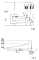
- FIG. 1 The construction of a 2-leg, 4-pulse engine is shown in Fig. 1. This is to generate a rotating field in the stator for the arrow indicated direction of rotation a control unit STE-PWM required, as Fig. 2 shows.
- the stator has eight poles, between which one is not wound Intermediate pole is arranged.
- the winding direction changes from Partial winding to partial winding and the partial windings of an excitation winding are distributed on poles, between which a pole not occupied by them is arranged.
- the field windings L1 and L3 or L2 and L4 capture the same poles, but opposite each other on each pole Have winding senses.
- the field windings L1 to L4 are switched on and off via semiconductor output stages T1 to T4, that is to say connected to and disconnected from the DC supply voltage U batt .
- the control takes place via pulse-width-modulated control signals and when the engine is started in a start phase consisting of position phase Tp and subsequent acceleration phase Tb, which extends over a predetermined or predeterminable time, such as the time diagram according to FIG. 3 shows.
- the position phase Tp can be, for example, 1200 ms and the acceleration phase Tb can be, for example, 10 ms.
- the pulse width ratio PWV continuously on e.g. 63% increases.
- This position phase Tp is sufficient, the motor in the direction of rotation gently in a predetermined position to bring from which he with the subsequent acceleration phase Tb in the speed is accelerated.
- the pulse width ratio to e.g. 75% increased. So that the start in the desired direction of rotation is continued, the excitation winding L1 switched off in the acceleration phase Tb and the excitation winding L3 when the excitation winding L2 is switched on.
- the excitation windings become L1 to L4 by the control unit STE-PWM in a known manner in successive Control phases determine what leads to the engine running continuously.
- the start phase with the position phase Tp and the acceleration phase Tb are stored as software in a microcomputer of the STE-PWM control unit, like the tax phases of the endurance run.
Landscapes
- Engineering & Computer Science (AREA)
- Power Engineering (AREA)
- Control Of Motors That Do Not Use Commutators (AREA)
Applications Claiming Priority (2)
| Application Number | Priority Date | Filing Date | Title |
|---|---|---|---|
| DE19921849 | 1999-05-11 | ||
| DE1999121849 DE19921849A1 (de) | 1999-05-11 | 1999-05-11 | Elektronisch kommutierbarer Motor |
Publications (2)
| Publication Number | Publication Date |
|---|---|
| EP1052767A2 true EP1052767A2 (fr) | 2000-11-15 |
| EP1052767A3 EP1052767A3 (fr) | 2002-11-20 |
Family
ID=7907799
Family Applications (1)
| Application Number | Title | Priority Date | Filing Date |
|---|---|---|---|
| EP00109534A Withdrawn EP1052767A3 (fr) | 1999-05-11 | 2000-05-04 | Moteur à commutation électrique |
Country Status (2)
| Country | Link |
|---|---|
| EP (1) | EP1052767A3 (fr) |
| DE (1) | DE19921849A1 (fr) |
Families Citing this family (1)
| Publication number | Priority date | Publication date | Assignee | Title |
|---|---|---|---|---|
| DE10116814A1 (de) * | 2001-04-04 | 2002-11-07 | Bosch Gmbh Robert | Verfahren zur Ableitung des Polradlagewinkels |
Family Cites Families (6)
| Publication number | Priority date | Publication date | Assignee | Title |
|---|---|---|---|---|
| FR2590423B1 (fr) * | 1985-11-21 | 1993-09-03 | Valeo | Procede et dispositif pour assurer le demarrage d'un moteur electrique a commutation electronique |
| BR8901539A (pt) * | 1989-03-27 | 1990-10-30 | Brasil Compressores Sa | Processo e circuito eletronico para controle de motor de corrente continua sem escovas |
| US5327053A (en) * | 1992-08-12 | 1994-07-05 | Seagate Technology, Inc. | Apparatus and method for detecting rotor position in a sensorless and brushless DC motor |
| US5466999A (en) * | 1994-08-15 | 1995-11-14 | Maxtor Corporation | Spindle motor start control process and apparatus |
| US5744921A (en) * | 1996-05-02 | 1998-04-28 | Siemens Electric Limited | Control circuit for five-phase brushless DC motor |
| IT1291608B1 (it) * | 1997-04-18 | 1999-01-11 | Sisme Immobiliare S P A | Disposizione a motore sincrono monofase a magneti permanenti |
-
1999
- 1999-05-11 DE DE1999121849 patent/DE19921849A1/de not_active Ceased
-
2000
- 2000-05-04 EP EP00109534A patent/EP1052767A3/fr not_active Withdrawn
Also Published As
| Publication number | Publication date |
|---|---|
| DE19921849A1 (de) | 2000-11-23 |
| EP1052767A3 (fr) | 2002-11-20 |
Similar Documents
| Publication | Publication Date | Title |
|---|---|---|
| EP1154555B1 (fr) | Système de commutation électronique pour un moteur à courant continu sans balai | |
| DE3884137T2 (de) | Bürstenloser Motor. | |
| DE69017152T2 (de) | Regelung eines bürstenlosen Motors mit mehreren Phasen und ohne Positionssensoren für den Rotor, unter Verwendung eines Systems der digitalen Filterung. | |
| EP1076408B1 (fr) | Procédé de démarrage d'un moteur à courant continu sans balais | |
| DE4009258C2 (de) | Verfahren und elektronische Regelschaltung zum Anlassen eines bürstenlosen Gleitstrommotors | |
| DE2837187C2 (fr) | ||
| EP1499008B1 (fr) | Méthode et système de commande pour la commutation électronique d'un moteur DC sans balais | |
| EP1382110B1 (fr) | Procede et dispositif pour determiner la position du rotor d'un moteur electrique comportant plusieurs phases de moteur | |
| DE3819062C3 (de) | Verfahren zur Steuerung von bürstenlosen Elektromotoren sowie Steuerschaltung hierfür | |
| EP1071200B1 (fr) | Moteur électroniquement commutable | |
| DE3819064C3 (de) | Verfahren zur Steuerung von bürstenlosen Elektromotoren sowie Steuerschaltung hierfür | |
| EP1232561B1 (fr) | Procede de demarrage d'un moteur a courant continu sans detecteur ni balai | |
| EP2567456B1 (fr) | Procédé et dispositif de commande pour faire fonctionner un moteur à courant continu triphasé sans balai | |
| DE102016222015A1 (de) | Elektrischer Antrieb und Verfahren zum Betrieb eines Elektromotors | |
| DE4404889A1 (de) | Elektrisches Antriebssystem für ein gleichstrombetriebenes Fahrzeug sowie Verfahren zum Steuern eines gleichstrombetriebenen Antriebs-Elektromotors | |
| EP1052767A2 (fr) | Moteur à commutation électrique | |
| DE4404926A1 (de) | Elektrisches Antriebssystem für ein gleichstrombetriebenes Fahrzeug sowie Verfahren zum Steuern eines gleichstrombetriebenen Antriebs-Elektromotors | |
| BE1029061B1 (de) | Verfahren zum Ansteuern eines mindestens zweiphasigen bürstenlosen Motors | |
| DE4122109A1 (de) | Verfahren und schaltungsanordnung zur anlaufsteuerung eines elektronisch kommutierten gleichstrommotors | |
| DE69502693T2 (de) | Steuerungsverfahren für einen elektrischen, bürstenlosen Gleichstrommotor | |
| EP0685927B1 (fr) | Méthode de freinage pour un moteur synchrone tournant inversement actionné par un réseau à cc | |
| EP0246522B1 (fr) | Commande de vitesse | |
| DE3119276A1 (de) | "verfahren und vorrichtung zum betreiben eines synchronmotors der bauart mit einem permanentmagnetrotor" | |
| DE69509143T2 (de) | Reluktanz-Schrittsynchronmotor | |
| DE19953265A1 (de) | Verfahren zum Anfahren eines Gleichstrommotors |
Legal Events
| Date | Code | Title | Description |
|---|---|---|---|
| PUAI | Public reference made under article 153(3) epc to a published international application that has entered the european phase |
Free format text: ORIGINAL CODE: 0009012 |
|
| AK | Designated contracting states |
Kind code of ref document: A2 Designated state(s): AT BE CH CY DE DK ES FI FR GB GR IE IT LI LU MC NL PT SE |
|
| AX | Request for extension of the european patent |
Free format text: AL;LT;LV;MK;RO;SI |
|
| PUAL | Search report despatched |
Free format text: ORIGINAL CODE: 0009013 |
|
| AK | Designated contracting states |
Kind code of ref document: A3 Designated state(s): AT BE CH CY DE DK ES FI FR GB GR IE IT LI LU MC NL PT SE |
|
| AX | Request for extension of the european patent |
Free format text: AL;LT;LV;MK;RO;SI |
|
| RIC1 | Information provided on ipc code assigned before grant |
Free format text: 7H 02P 6/22 A, 7H 02P 6/20 B |
|
| 17P | Request for examination filed |
Effective date: 20030520 |
|
| AKX | Designation fees paid |
Designated state(s): DE ES FR GB IT SE |
|
| STAA | Information on the status of an ep patent application or granted ep patent |
Free format text: STATUS: THE APPLICATION IS DEEMED TO BE WITHDRAWN |
|
| 18D | Application deemed to be withdrawn |
Effective date: 20031202 |