EP1052809A1 - Réseau de communication - Google Patents
Réseau de communication Download PDFInfo
- Publication number
- EP1052809A1 EP1052809A1 EP99303671A EP99303671A EP1052809A1 EP 1052809 A1 EP1052809 A1 EP 1052809A1 EP 99303671 A EP99303671 A EP 99303671A EP 99303671 A EP99303671 A EP 99303671A EP 1052809 A1 EP1052809 A1 EP 1052809A1
- Authority
- EP
- European Patent Office
- Prior art keywords
- packet
- value
- packets
- phase
- node
- Prior art date
- Legal status (The legal status is an assumption and is not a legal conclusion. Google has not performed a legal analysis and makes no representation as to the accuracy of the status listed.)
- Withdrawn
Links
Images


Classifications
-
- H—ELECTRICITY
- H04—ELECTRIC COMMUNICATION TECHNIQUE
- H04L—TRANSMISSION OF DIGITAL INFORMATION, e.g. TELEGRAPHIC COMMUNICATION
- H04L47/00—Traffic control in data switching networks
- H04L47/10—Flow control; Congestion control
- H04L47/28—Flow control; Congestion control in relation to timing considerations
- H04L47/286—Time to live
-
- H—ELECTRICITY
- H04—ELECTRIC COMMUNICATION TECHNIQUE
- H04L—TRANSMISSION OF DIGITAL INFORMATION, e.g. TELEGRAPHIC COMMUNICATION
- H04L12/00—Data switching networks
- H04L12/28—Data switching networks characterised by path configuration, e.g. LAN [Local Area Networks] or WAN [Wide Area Networks]
- H04L12/42—Loop networks
- H04L12/427—Loop networks with decentralised control
- H04L12/433—Loop networks with decentralised control with asynchronous transmission, e.g. token ring, register insertion
-
- H—ELECTRICITY
- H04—ELECTRIC COMMUNICATION TECHNIQUE
- H04L—TRANSMISSION OF DIGITAL INFORMATION, e.g. TELEGRAPHIC COMMUNICATION
- H04L47/00—Traffic control in data switching networks
- H04L47/10—Flow control; Congestion control
-
- H—ELECTRICITY
- H04—ELECTRIC COMMUNICATION TECHNIQUE
- H04L—TRANSMISSION OF DIGITAL INFORMATION, e.g. TELEGRAPHIC COMMUNICATION
- H04L47/00—Traffic control in data switching networks
- H04L47/10—Flow control; Congestion control
- H04L47/13—Flow control; Congestion control in a LAN segment, e.g. ring or bus
-
- H—ELECTRICITY
- H04—ELECTRIC COMMUNICATION TECHNIQUE
- H04L—TRANSMISSION OF DIGITAL INFORMATION, e.g. TELEGRAPHIC COMMUNICATION
- H04L47/00—Traffic control in data switching networks
- H04L47/10—Flow control; Congestion control
- H04L47/32—Flow control; Congestion control by discarding or delaying data units, e.g. packets or frames
Definitions
- the present invention relates to a communications network and, in particular, to a mechanism for the removal of expired packets from such a network.
- TTL time-to-live
- a method of removing expired packets from a communications network characterised by comparing a phase value received with the packet with a phase value previously received via the network from a master node, and discarding the packet when the difference between the phase values exceeds a predetermined amount.
- a method of operating a communications network including:
- the invention provides a new time-to-live mechanism that does not require modification of a header field and that does not require complex synchronisation or processing.
- the invention is therefore particularly suitable for use with high-speed packets.
- Packets are created with a phase field value, such as the PH field described in the examples below.
- the phase field value indicates the current time "phase”.
- a control packet output by a master node may travel around the network to inform each node of a new phase value.
- the phase value at each node is thus regularly updated.
- the updating of the phase value may be by incrementing the value by 1 (modulo 3).
- a node determines that the phase value carried with a packet received at the node differs from the last phase value received from the master node by more than a predetermined amount, then the packet is treated as time-expired and is purged from the network.
- the method includes transmitting at least some of the packets via one or more transit nodes on a continuous-flow transmission path.
- a continuous-flow transmission path is one which transmits packets in a steady, continuous fashion without using queues or other variable delays.
- the packets are optical packets and the continuous-flow transmission path is a continuous optical path.
- part or all of the continuous-flow transmission path may be in the electrical domain.
- the intention also encompasses network nodes adapted to implement the method of the first aspect.
- a communications network 1 comprises concentric outer and inner rings 2.1, 2.2.
- the rings carry optical packets.
- a number of nodes 3a to 3g are connected to the rings.
- each of the nodes 3a to 3g is an internet protocol router.
- one of the routers, for example 3a outputs an optical packet addressed to another of the routers, for example 3d, onto one of the dual concentric rings.
- the optical packet output by node 3a carries the network address of node 3d in an address field in the packet header.
- the packet passes around the ring.
- the packet address is compared with the address of the respective node if the packet is not addressed to a given intermediate node, then the packet passes on to the next node, and so on.
- the address is read and the packet is recognised as being intended for receipt at that node.
- the packet in the case of a unicast transmission is removed from the network at that node. It may then, for example, be converted to the electrical domain for onwards transmission to a customer terminal on an electronic network connected to the respective node.
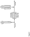
- Figure 2 shows the flow of received and transmitted data packets at one of the nodes on one of the fibre rings.
- An incoming data packet is (i) sent to host receive queue (if it has reached its destination) or (ii) is passed over for onward transmission.
- a multicast packet may both be sent to the host receive queue and also be forwarded for onward transmission.
- Packets for onward transmission are treated according to their priority: a low-priority packet is passed to a transit queue.
- An express high-priority, packet is passed immediately to the outgoing path without queuing. When capacity on the ring allows, a packet from one of the transmit queues may be passed to the outgoing path. Multiple transmit queues may be used to manage prioritisation of outgoing traffic from the node.
- the optical fibre rings and the nodes are configured to provide a continuous optical path for express packets.
- the path may be a continuous optical transmission path.
- the continuous optical transmission path may contain a substantially fixed delay as in Figure 3.
- the path may contain storage elements such as FIFO (first-in first-out) buffer.
- FIFO first-in first-out
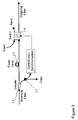
- Figure 3 shows the node architecture developed by the inventors and term the "copy eject and insert” (CEI) architecture.
- An incoming fibre from one of the optical rings passes to a coupler 3.1. From the coupler 3.1, one optical path passes through a further length of fibre 3.3 providing a fixed delay to an optical crossbar switch 3.4.
- An outgoing fibre connected in the fibre ring passes from one of the output ports of the crossbar switch.
- the other output from the coupler 3.1 is split again, for example, using a further coupler 3.2.
- One branch of the output from this further coupler is used to provide a copy of the optical packet on the incoming fibre. This copy may be passed, for example, to the post receive queue.
- the other branch of the output of the further coupler passes to control circuits.
- control circuits may, for example, read a header carried with the optical packet, and carry out associated logic operations.
- a control output is generated by the control circuits and passes to the crossbar switch. If the control circuits determine that the packet is addressed to the respective node, then the crossbar switch is set to the cross state in order to eject the packet (in the case of a unicast transmission).
- a further function carried out by the control circuits is to determine whether the time-to-live (TTL) of a packet has expired. If the time-to-live is determined to have expired, then again a control signal is sent to the switch to cause such a packet to be ejected from the onwards transmission path.
- TTL time-to-live
- a control signal is sent to the switch to cause such a packet to be ejected from the onwards transmission path.
- a value is written in a phase field "PH" in the packet header.
- One of the nodes functions as a master node.
- the master node outputs multicast express control packets that travel around each ring to inform each node of the current phase value.
- the phase value is regularly updated, at a rate of at least once per round-trip time for express packet travel around the ring.
- the updating of the phase value is carried out by the master node incrementing the value by 1 (modulo 3).
- Each ring periodically receives and stores the current phase value as indicated by one of the multicast express control packets from the master node.
- the control logic in the node determines whether the value in the PH field of the received express packet is such that: (current_phase-PH)mod3 ⁇ 1,
- the packet is expired and should be purged from the ring. This may be the case, for example, because the packet is addressed to a node which is currently malfunctioning or because there is an error in the address of the packet.
- an express packet that has completed one full revolution of the ring may over-run by between approximately 0 and 1 revolutions before being purged, with an average over-run distance of about 0.5 revolutions.
- the time-to-live mechanism operates independently on each of the two fibre rings, and there are independent master nodes for each of the two rings.
- a suitable election mechanism is as follows: When a node detects that the sequence of current_phase control packets has been interrupted, it may transmit a multicast express control packet which signals a 'bid' to become the master node. The node may bid only if it has detected no other recent contending bids. If the node detects a current_phase control packet or a contending bid before receiving back its own bid packet, then its own bid is void; in that case the node must wait a random time before it may submit a further bid subject to the rules above.
- a node If however a node receives back its own bid without being pre-empted, then it assumes it is duly 'elected' to serve as the master node; it purges all further counter bids and begins to transmit the sequence of current_phase control packets. If a master node detects a current_phase control packet of which it is not the source, then it must cease acting as the master.
- the phase field mechanism is used to determine the identity of time expired express packets and a separate mechanism is used for other low-priority packets.
- Such low-priority packets are, as indicated above, identified by a specific value in the PH field.
- Figure 4 shows the format of one of the optical packets including the PH field in the optical MAC header.
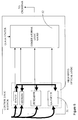
- Figure 5 shows the control logic subsystem in more detail. It includes optical logic stages 51 and combinatorial electronic logic gates 52.
- the four optical blocks (synch, address recognition PH reader and Unicast/Multicast) each have copies of the optical packet to the input.
- the output from the synchronisation block is an optical path to each of the other three optical blocks.
- the synch block may be based on one of the self-synchronisation techniques we have described in our patent EP-B-687370 (eg. using pulses separated by 1.5 bit periods input to an optical AND gate).
- the address recognition block may be based on the technique we have described before in that patent. Addresses are coded using specially selected binary words, and recognised by inputting address and target word to an optical AND gate.
- the output from the AND gate is converted to give an output from the block that is an electrical binary signal that says packet ADDRESSEE matches/does not match local address.
- the PH may be two optical AND gates, each having the optical packet as one input and a synch pulse as the other input - this synch pulse timed to overlap with one of the PH bits.
- the output from PH reader block is two parallel electrical binary signals - each denoting one of the PH bits.
- the UNI/MULTI reader may be one optical AND gate, having the optical packet as one input and a synch pulse as the other input - this synch pulse timed to overlap with the UM bit.
- the output from UNI/MULTI reader block is one electrical binary signal - denoting unicast/multicast.
- This part performs the logic which is set out in - the table below describing the action of the node for various types of packet (e.g. multicast low-priority transit packet, etc).
- the output from this electronic logic is a binary electrical signal to set the 2x2 cross bar optical switch configuration.
- the optical stage is ultrafast - e.g. using four-wave mixing in semiconductor optical amplifier, or TOAD device, etc. to implement the optical AND gate. Since the electronic logic required is simple it is possible to construct suitable fast circuit using hard-wired combinatorial logic.
Landscapes
- Engineering & Computer Science (AREA)
- Computer Networks & Wireless Communication (AREA)
- Signal Processing (AREA)
- Data Exchanges In Wide-Area Networks (AREA)
Priority Applications (10)
| Application Number | Priority Date | Filing Date | Title |
|---|---|---|---|
| EP99303671A EP1052809A1 (fr) | 1999-05-11 | 1999-05-11 | Réseau de communication |
| CNB008073422A CN1178432C (zh) | 1999-05-11 | 2000-05-05 | 通信系统和在通信系统中操作节点的方法 |
| EP00927505A EP1177658B1 (fr) | 1999-05-11 | 2000-05-05 | Reseau de communications |
| AT00927505T ATE343884T1 (de) | 1999-05-11 | 2000-05-05 | Kommunikationsnetzwerk |
| DE60031519T DE60031519T2 (de) | 1999-05-11 | 2000-05-05 | Kommunikationsnetzwerk |
| CNB008073163A CN1165135C (zh) | 1999-05-11 | 2000-05-05 | 通信网络、其操作方法、节点、和从通信网络中去除期满分组的方法 |
| CA002371037A CA2371037C (fr) | 1999-05-11 | 2000-05-05 | Noeud et methode pour la suppression de paquets expires dans un reseau de communication |
| PCT/GB2000/001716 WO2000069127A1 (fr) | 1999-05-11 | 2000-05-05 | Reseau de communications |
| AU45905/00A AU761768B2 (en) | 1999-05-11 | 2000-05-05 | Communications network |
| US09/959,280 US7561522B1 (en) | 1999-05-11 | 2000-05-05 | Communications network having mechanism for removal of time-expired packets from the network |
Applications Claiming Priority (1)
| Application Number | Priority Date | Filing Date | Title |
|---|---|---|---|
| EP99303671A EP1052809A1 (fr) | 1999-05-11 | 1999-05-11 | Réseau de communication |
Publications (1)
| Publication Number | Publication Date |
|---|---|
| EP1052809A1 true EP1052809A1 (fr) | 2000-11-15 |
Family
ID=8241378
Family Applications (1)
| Application Number | Title | Priority Date | Filing Date |
|---|---|---|---|
| EP99303671A Withdrawn EP1052809A1 (fr) | 1999-05-11 | 1999-05-11 | Réseau de communication |
Country Status (1)
| Country | Link |
|---|---|
| EP (1) | EP1052809A1 (fr) |
Cited By (2)
| Publication number | Priority date | Publication date | Assignee | Title |
|---|---|---|---|---|
| EP1320226A3 (fr) * | 2001-12-13 | 2004-03-31 | NTT DoCoMo, Inc. | Routeur, dispositif terminal, système de communication et procédé de routage |
| US8125895B2 (en) * | 2004-07-14 | 2012-02-28 | Fujitsu Limited | Network looping detecting apparatus |
Citations (2)
| Publication number | Priority date | Publication date | Assignee | Title |
|---|---|---|---|---|
| US4682326A (en) * | 1985-11-27 | 1987-07-21 | General Electric Company | Method and apparatus for maintaining a dynamic logical ring in a token passing lan |
| US5041963A (en) * | 1988-12-29 | 1991-08-20 | Intel Corporation | Local area network with an active star topology comprising ring controllers having ring monitor logic function |
-
1999
- 1999-05-11 EP EP99303671A patent/EP1052809A1/fr not_active Withdrawn
Patent Citations (2)
| Publication number | Priority date | Publication date | Assignee | Title |
|---|---|---|---|---|
| US4682326A (en) * | 1985-11-27 | 1987-07-21 | General Electric Company | Method and apparatus for maintaining a dynamic logical ring in a token passing lan |
| US5041963A (en) * | 1988-12-29 | 1991-08-20 | Intel Corporation | Local area network with an active star topology comprising ring controllers having ring monitor logic function |
Cited By (3)
| Publication number | Priority date | Publication date | Assignee | Title |
|---|---|---|---|---|
| EP1320226A3 (fr) * | 2001-12-13 | 2004-03-31 | NTT DoCoMo, Inc. | Routeur, dispositif terminal, système de communication et procédé de routage |
| US7408879B2 (en) | 2001-12-13 | 2008-08-05 | Ntt Docomo, Inc. | Router, terminal apparatus, communication system and routing method |
| US8125895B2 (en) * | 2004-07-14 | 2012-02-28 | Fujitsu Limited | Network looping detecting apparatus |
Similar Documents
| Publication | Publication Date | Title |
|---|---|---|
| JP2942875B2 (ja) | ディジタル通信システム | |
| US6553030B2 (en) | Technique for forwarding multi-cast data packets | |
| CN102132535B (zh) | 在通信网中传输数据分组的方法和交换装置 | |
| US7260102B2 (en) | Traffic switching using multi-dimensional packet classification | |
| US8787397B2 (en) | High speed ring/bus | |
| US4761780A (en) | Enhanced efficiency Batcher-Banyan packet switch | |
| US20020085565A1 (en) | Technique for time division multiplex forwarding of data streams | |
| US20020085567A1 (en) | Metro switch and method for transporting data configured according to multiple different formats | |
| EP1177658B1 (fr) | Reseau de communications | |
| US20020167950A1 (en) | Fast data path protocol for network switching | |
| US7760625B2 (en) | Exchange node and exchange node control method | |
| WO2002054688A1 (fr) | Technique de qualite de service pour un reseau de communication de donnees | |
| US20020085507A1 (en) | Address learning technique in a data communication network | |
| CN110460548B (zh) | 基于多平面的时间触发以太网交换机及调度分组交换方法 | |
| US7376138B1 (en) | Optical communications network | |
| US6976096B1 (en) | Method and apparatus for controlling the admission of data into a network element | |
| US20020085545A1 (en) | Non-blocking virtual switch architecture | |
| US6337860B1 (en) | Redundancy termination | |
| EP1340344B1 (fr) | Gestion du temps d'attente dans un reseau | |
| EP1052808A1 (fr) | Réseau de communication utilisant classes de priorité | |
| US7206310B1 (en) | Method and apparatus for replicating packet data with a network element | |
| EP1686734A1 (fr) | Procédé et dispositif pour transmettre un signal optique dans un réseau optique par rafales utilisant le temps d'arrivée | |
| EP1052807A1 (fr) | Réseau de communications utilisant classes de priorité | |
| US7006515B1 (en) | Isochronous queue and buffer management | |
| US7321558B2 (en) | Method and apparatus in a computer network |
Legal Events
| Date | Code | Title | Description |
|---|---|---|---|
| PUAI | Public reference made under article 153(3) epc to a published international application that has entered the european phase |
Free format text: ORIGINAL CODE: 0009012 |
|
| AK | Designated contracting states |
Kind code of ref document: A1 Designated state(s): AT BE CH CY DE DK ES FI FR GB GR IE IT LI LU MC NL PT SE |
|
| AX | Request for extension of the european patent |
Free format text: AL;LT;LV;MK;RO;SI |
|
| STAA | Information on the status of an ep patent application or granted ep patent |
Free format text: STATUS: THE APPLICATION IS DEEMED TO BE WITHDRAWN |
|
| 18D | Application deemed to be withdrawn |
Effective date: 20000912 |