EP1052822A1 - Démodulateur numérique programmable pour modulations OFDM - Google Patents
Démodulateur numérique programmable pour modulations OFDM Download PDFInfo
- Publication number
- EP1052822A1 EP1052822A1 EP00201577A EP00201577A EP1052822A1 EP 1052822 A1 EP1052822 A1 EP 1052822A1 EP 00201577 A EP00201577 A EP 00201577A EP 00201577 A EP00201577 A EP 00201577A EP 1052822 A1 EP1052822 A1 EP 1052822A1
- Authority
- EP
- European Patent Office
- Prior art keywords
- module
- frequency
- data
- demodulator
- processing
- Prior art date
- Legal status (The legal status is an assumption and is not a legal conclusion. Google has not performed a legal analysis and makes no representation as to the accuracy of the status listed.)
- Granted
Links
Images

Classifications
-
- H—ELECTRICITY
- H04—ELECTRIC COMMUNICATION TECHNIQUE
- H04L—TRANSMISSION OF DIGITAL INFORMATION, e.g. TELEGRAPHIC COMMUNICATION
- H04L27/00—Modulated-carrier systems
- H04L27/26—Systems using multi-frequency codes
- H04L27/2601—Multicarrier modulation systems
- H04L27/2647—Arrangements specific to the receiver only
-
- H—ELECTRICITY
- H04—ELECTRIC COMMUNICATION TECHNIQUE
- H04L—TRANSMISSION OF DIGITAL INFORMATION, e.g. TELEGRAPHIC COMMUNICATION
- H04L27/00—Modulated-carrier systems
Definitions
- the invention relates to a transmission system comprising at least one transmitter and a receiver, said receiver comprising a digital data demodulator.
- the invention also relates to a receiver and a demodulator intended for use in such a system.
- the invention has important applications in the field of digital modulations.
- the draft DVB-T standard (from English Digital Video Broadcasting for Terrestrial) defined by ETSI and relating to the broadcasting of digital television programs by links hertziennes describes an example of such a transmission system.
- this project provides the use of multicarrier modulations, which allow the best use of the characteristics of the transmission channel.
- the multi-carrier transmission technique consists in multiplexing in frequency N carriers which are modulated by points of a constellation (for example points of a constellation MAQ).
- N carriers which are modulated by points of a constellation (for example points of a constellation MAQ).
- Each symbol transmitted (called the FDM symbol in English "Frequency Division Multiplexing ”) therefore corresponds to a block of N points, each point of the block modulating one of the N carriers.
- the sampling frequency of the transmitted signal is therefore much higher than the frequency of FDM symbols.
- the level of demodulator certain demodulation functions are performed at a frequency of the order of frequency of sampling of data received, while others are carried out at a frequency of the order of the symbol frequency.
- a static communication model to manage data exchanges inside such a demodulator.
- Use a template static communication consists in carrying out specific functions, at times determined, by running programs that repeat themselves at the same frequency, so that ability to provide data at a regular rate.
- This type of communication model is advantageous because it ensures that all data is transmitted correctly and therefore that the functions are executed correctly.
- the object of the invention is to propose a demodulator which provides a solution to this problem.
- the invention therefore consists in separating the architecture of the demodulator into two parts communicating through an interface.
- one of these parts (the first module) is dedicated to the processing of functions which must take place at a frequency on the order of the sampling frequency.
- the other part (the second module) is dedicated to the processing of functions which must be performed at a frequency of the order of the symbol frequency.
- the operating programs of the first module have a repetition frequency of the order of the sampling frequency. Consequently, instructions relating to the processing of the different carriers are only stored a number minimum of times. The memory size required for storing said programs is therefore reduced to a minimum size.
- the invention also has the advantage of providing an architecture which can be used for transmission systems which use single carrier modulations, for example for cable or satellite transmission systems.
- the frequency sampling frequency and symbol frequency are of the same order of magnitude so that the problem mentioned above does not arise.
- only one of the modules is used (the first module).
- the operating programs of this module have a frequency of repetition of the order of the symbol frequency.
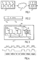
- FIG. 1 an example of a digital transmission system has been represented according to the invention between a transmitter 1 and a receiver 2 via a transmission medium 3.
- the transmitter 1 includes a data source 11, a source encoder 12, a channel encoder 13, and a digital modulator 14.
- the receiver 2 includes a digital demodulator 21, a channel decoder 22, and a source decoder 23.
- the transmission medium 3 can be different natures, for example, it can be a cable network, a satellite channel or a radio channel.
- the modulation used is chosen according to the transmission medium for take into account the characteristics of the transmission medium. In particular, we use single carrier modulations for cable and satellite transmissions, and multicarrier modulations for radio transmissions because the technique of multicarrier modulation offers good protection against the selectivity of radio channels, multi-path propagation and interference between radio channels.
- the multicarrier modulations used are OFDM modulations (from the English "Orthogonal Frequency Division Multiplexing").
- the OFDM technique consists in multiplexing in frequency N orthogonal carriers which are modulated by points of a constellation (for example points of an MAQ constellation). Each transmitted symbol (called OFDM symbol) therefore corresponds to a block of N points, each point of the block modulating one of the N orthogonal carriers.
- FIG. 2 we have shown the structure of an example OFDM symbol such that defined in the draft DVB-T standard.
- Each symbol is composed of a guard interval Tg suM of a useful part Tu.
- the guard interval Tg is used to eliminate the interference between the symbols.
- the nature of a carrier (useful carrier, carrier of data or carrier of control information) is determined by its location in I OFDM symbol.
- the carriers of control information are mainly used for the channel synchronization and estimation. Some of the treatments to be performed on these carriers therefore take place at a frequency of the order of the symbol frequency. However the processing to be carried out on the carriers of useful data is all carried out at a frequency of the order of the sampling frequency.
- FIG. 3 there is shown a block diagram of the architecture of a digital demodulator 21 according to the invention.
- These calculation units PU i communicate with each other via an interconnection network INT.
- the digital receiver described here is a programmable receiver which can be programmed to be used for different types of modulation. That implies in particular that the symbol frequency is not known a priori.
- the architecture used is a static architecture, periodic moments of communication (t0, t1, ...) are provided for transfer data (D0, D1, ...) from one calculation unit to another (see Figure 4), regardless of the value of the symbol frequency. It may therefore happen that no data is only available when a communication must take place (for example at time t2).
- a validity indicator Iv is therefore associated with each communication interval to inform the unit of calculation which expects a data whether or not there is a data in this time interval Communication. For example at time t2, as no data is available the validity indicator has a zero value.
- the PU K calculation unit comprises a second module 32 and an interface module 34.
- the second module 32 is capable of processing second demodulation functions according to one or more programs 36 which are repeated at a second frequency.
- An exemplary embodiment of an interface module 34 is shown in detail in FIG. 5. It includes selection means 40 for selecting data to be transmitted, a FIFO memory 42 for storing the data to be transmitted to the second module 32, a FIFO memory 44 for storing results provided by the second module, and transmission means 46 for transmitting to the first module 30 the results stored in memory 44.
- This interface module 34 is controlled by PGM programs K, j in particular by a PGM K, 1 writing program and by a PGM K, 2 reading program.
- the data received by the calculation unit PU K are either symbols containing N carriers, or any data which must be transmitted as such to the second module 32.
- the selection means 40 are used when the data received is a symbol, for select, in this symbol, the carriers to be transmitted to the second module 32 (only the carriers of control information must be transmitted).
- the selection means 40 are controlled by the writing program PGM K, 1 . They include a counter 50 and a table 52.
- the counter 50 numbers, in their order of appearance, the carriers contained in the symbol.
- Table 52 contains for each carrier number a transfer identifier It which indicates whether or not the corresponding carrier must be transmitted to the second module 32, that is to say whether it must be copied into the FIFO memory 42.
- FIFO memory 42 contains on the one hand the data to be transmitted to the second module 32, and on the other hand for each data item a function identifier If indicating the function source and / or destination function of the data. This If function identifier allows the second module 32 of knowing where to store the corresponding data for its processing ulterior.
- the second module 32 performs one or more functions which provide results. These results are stored in FIFO memory 44, with a function identifier If which indicates the source function and / or the destination function of the result. This identifier of If function makes it possible to manage, with the transmission means 46, the instant of communication to which a result must be transmitted to the first module 30.
- the transmission means 46 are controlled by the reading program PGM K, 2 .
- the program PGM K, 2 includes instructions which indicate the type of communication which must take place at the time of communication considered. Each type of communication corresponds to the transmission of a result of a certain type. The type of a result is indicated by the function identifier If associated with it.
- the transmission means 46 consist of a correspondence table which indicates the correspondence between a type of communication and the type or types of results to be transmitted. For example, there can be two different types of communications C 1 and C 2 , a communication of type C 1 corresponding to the transmission of a result whose function identifier If is equal to Z1 or to Z2, and a communication of type C 2 corresponding to the transmission of a result whose function identifier is equal to Z3.
- the reading program PGM K, 2 consults the correspondence table to determine whether the function identifier of the output result of the FIFO memory 44 corresponds to the type of communication. In this case the output result from the FIFO memory is transferred to the first module, with a validity identifier Iv equal to one. And the reading program goes to the next datum. Otherwise, the output result is not transferred (which means that it remains in the FIFO memory) and the validity indicator Iv associated with the current communication instant is set to zero.
- This mechanism makes it possible to guarantee that the results are transmitted in instants of communication that are correct in relation to the needs of the first module 30.
- FIG. 7 shows an example of a demodulator according to the invention for single-carrier modulations.
- This demodulator comprises a first module 30, a second module 32 and an interface module 34.
- the first module 30 essentially comprises a calculation unit PU 10 which transposes the received signal into baseband, a calculation unit PU 20 which performs the processing operations relating to synchronization, a PU 30 calculation unit which performs filtering operations for the recovery of symbols, and a PU 40 decoding unit.
- the interface module 34 and the second module 32 are grouped together in a calculation unit PU 7 .
- the PU 7 calculation unit is not used. All of the demodulation functions are processed by the first module 30.
- the programs which manage the operation of the calculation units PU 10 , PU 20 , PU 30 and PU 40 are repeated at a frequency of the order of the symbol frequency.
- a programmable digital demodulator has been described, usable for different types of modulations.
- the invention is not limited to this example. She is in particular applicable to an OFDM demodulator working at a predetermined symbol frequency, and in which communications (including the communication times at which the data must be transmitted) are easier to manage than in the example which has been described. It's clear that in this case the interface module can be simplified compared to that which has been described.
Landscapes
- Engineering & Computer Science (AREA)
- Computer Networks & Wireless Communication (AREA)
- Signal Processing (AREA)
- Digital Transmission Methods That Use Modulated Carrier Waves (AREA)
- Communication Control (AREA)
- Circuits Of Receivers In General (AREA)
Abstract
Description
- un premier module dédié au traitement de premières fonctions de démodulation conformément à au moins un premier programme qui se répète à une première fréquence,
- un second module susceptible d'être dédié au traitement de secondes fonctions de démodulation conformément à au moins un second programme qui se répète à une seconde fréquence,
- et un module d'interface pour échanger des données entre lesdits modules.
- la figure 1 représente un exemple de système de transmission selon l'invention,
- la figure 2 représente la structure d'un symbole FDM,
- la figure 3 est un schéma de l'architecture d'un démodulateur numérique selon l'invention,
- la figure 4 est un schéma explicatif de la gestion des communications internes dans un démodulateur tel que représenté sur la figure 3,
- la figure 5 est un schéma d'un exemple de module d'interface d'un démodulateur selon l'invention,
- la figure 6 est un schéma d'un démodulateur OFDM selon l'invention
- la figure 7 est un schéma d'un démodulateur selon l'invention pour les modulations monoporteuses utilisées dans les systèmes de diffusion de programmes numériques par câble ou par satellite définis par les projets de normes DVB.
- l'unité PU3 transmet des symboles à l'unité PU7,
- l'unité PU7 transmet à l'unité PU2 des résultats relatifs à la synchronisation,
- l'unité PU7 transmet à l'unité PU4 des résultats relatifs à la correction de canal.
Claims (10)
- Système de transmission comportant au moins un émetteur et un récepteur, ledit récepteur comportant un démodulateur numérique de données, caractérisé en ce que ledit démodulateur comporte:un premier module (30) dédié au traitement de premières fonctions de démodulation conformément à au moins un premier programme (PGMi) qui se répète à une première fréquence,un second module (32) susceptible d'être dédié au traitement de secondes fonctions de démodulation conformément à au moins un second programme (36) qui se répète à une seconde fréquence,et un module d'interface (34) pour échanger des données entre lesdits modules.
- Système de transmission selon la revendication 1, caractérisé en ce que le module d'interface comporte des moyens de sélection (40) pour sélectionner les données à transmettre au second module.
- Système de transmission selon la revendication 1, caractérisé en ce que ledit module d'interface comporte au moins une mémoire (42, 44) de type FIFO.
- Système de transmission selon la revendication 2, dans lequel les données reçues sont formatées en blocs, chaque bloc contenant des données utiles et des informations de contrôle, caractérisé en ce que les moyens de sélection sélectionnent au moins certaines informations de contrôle, et en ce que ladite seconde fréquence est de l'ordre de la fréquence desdits blocs.
- Récepteur comportant un démodulateur numérique de données, caractérisé en ce que ledit démodulateur comporte:un premier module (30) dédié au traitement de premières fonctions de démodulation conformément à au moins un premier programme (PGMi,j) qui se répète à une première fréquence,un second module (32) susceptible d'être dédié au traitement de secondes fonctions de démodulation conformément à au moins un second programme (PGMK,j) qui se répète à une seconde fréquence,et un module d'interface (34) pour échanger des données entre lesdits modules.
- Récepteur selon la revendication 5, caractérisé en ce que le module d'interface comporte des moyens de sélection (40) pour sélectionner les données à transmettre au second module.
- Récepteur selon la revendication 6, destiné à recevoir des données formatées en blocs, chaque bloc contenant des données utiles et des informations de contrôle, caractérisé en ce que les moyens de sélection sélectionnent au moins certaines informations de contrôle, et en ce que ladite seconde fréquence est de l'ordre de la fréquence desdits blocs.
- Démodulateur numérique de données caractérisé en ce qu'il comporte:un premier module (30) dédié au traitement de premières fonctions de démodulation conformément à au moins un premier programme (PGMi,j) qui se répète à une première fréquence,un second module (32) susceptible d'être dédié au traitement de secondes fonctions de démodulation conformément à au moins un second programme (PGMK,j) qui se répète à une seconde fréquence,et un module d'interface (34) pour échanger des données entre lesdits modules.
- Démodulateur selon la revendication 8, caractérisé en ce que le module d'interface comporte des moyens de sélection (40) pour sélectionner les données à transmettre au second module.
- Démodulateur selon la revendication 9, destiné à recevoir des données formatées en blocs, chaque bloc contenant des données utiles et des informations de contrôle, caractérisé en ce que les moyens de sélection sélectionnent au moins certaines informations de contrôle, et en ce que ladite seconde fréquence est de l'ordre de la fréquence desdits blocs.
Applications Claiming Priority (2)
| Application Number | Priority Date | Filing Date | Title |
|---|---|---|---|
| FR9906018 | 1999-05-11 | ||
| FR9906018 | 1999-05-11 |
Publications (2)
| Publication Number | Publication Date |
|---|---|
| EP1052822A1 true EP1052822A1 (fr) | 2000-11-15 |
| EP1052822B1 EP1052822B1 (fr) | 2009-11-11 |
Family
ID=9545484
Family Applications (1)
| Application Number | Title | Priority Date | Filing Date |
|---|---|---|---|
| EP00201577A Expired - Lifetime EP1052822B1 (fr) | 1999-05-11 | 2000-05-02 | Démodulateur numérique programmable pour modulations OFDM |
Country Status (4)
| Country | Link |
|---|---|
| US (1) | US6754281B1 (fr) |
| EP (1) | EP1052822B1 (fr) |
| JP (1) | JP2000341245A (fr) |
| DE (1) | DE60043275D1 (fr) |
Families Citing this family (5)
| Publication number | Priority date | Publication date | Assignee | Title |
|---|---|---|---|---|
| AU2002251852A1 (en) * | 2001-02-02 | 2002-08-19 | Rosum Corporation | Services based on position location using broadcast digital television signals |
| US8754807B2 (en) | 2001-02-02 | 2014-06-17 | Trueposition, Inc. | Time, frequency, and location determination for femtocells |
| US20020184653A1 (en) | 2001-02-02 | 2002-12-05 | Pierce Matthew D. | Services based on position location using broadcast digital television signals |
| US20050251844A1 (en) * | 2001-02-02 | 2005-11-10 | Massimiliano Martone | Blind correlation for high precision ranging of coded OFDM signals |
| US8583845B2 (en) * | 2008-08-07 | 2013-11-12 | Nec Corporation | Multi-processor system and controlling method thereof |
Citations (2)
| Publication number | Priority date | Publication date | Assignee | Title |
|---|---|---|---|---|
| EP0340978A2 (fr) * | 1988-05-02 | 1989-11-08 | International Standard Electric Corporation | Appareil de modulation-démodulation |
| EP0353890A2 (fr) * | 1988-08-02 | 1990-02-07 | International Business Machines Corporation | Serveurs centraux de télécommunication avec traitement d'information |
Family Cites Families (8)
| Publication number | Priority date | Publication date | Assignee | Title |
|---|---|---|---|---|
| US4709344A (en) * | 1985-10-02 | 1987-11-24 | Motorola, Inc. | Programmable multifrequency digital tone receiver |
| JP2947405B2 (ja) * | 1995-02-21 | 1999-09-13 | 日本ビクター株式会社 | 周波数分割多重信号受信装置 |
| JP2713252B2 (ja) * | 1995-07-21 | 1998-02-16 | 株式会社日立製作所 | パケット位相同期回路 |
| CN1102304C (zh) * | 1996-07-08 | 2003-02-26 | 株式会社建伍 | Am数据多重调制波信号解调装置 |
| JP3289610B2 (ja) * | 1996-07-31 | 2002-06-10 | 日本ビクター株式会社 | Ofdm復調装置及びその方法 |
| US5995483A (en) * | 1996-08-22 | 1999-11-30 | Tellabs Operations, Inc. | Apparatus and method for upstream clock synchronization in a multi-point OFDM/DMT digital communication system |
| US6549242B1 (en) * | 1997-04-04 | 2003-04-15 | Harris Corporation | Combining adjacent TV channels for transmission by a common antenna |
| JP3156635B2 (ja) * | 1997-05-30 | 2001-04-16 | 日本ビクター株式会社 | 直交周波数分割多重信号伝送方法並びに直交周波数分割多重信号送信装置及びそれに用いるidft演算装置 |
-
2000
- 2000-05-02 DE DE60043275T patent/DE60043275D1/de not_active Expired - Lifetime
- 2000-05-02 EP EP00201577A patent/EP1052822B1/fr not_active Expired - Lifetime
- 2000-05-08 JP JP2000134365A patent/JP2000341245A/ja active Pending
- 2000-05-10 US US09/568,287 patent/US6754281B1/en not_active Expired - Lifetime
Patent Citations (2)
| Publication number | Priority date | Publication date | Assignee | Title |
|---|---|---|---|---|
| EP0340978A2 (fr) * | 1988-05-02 | 1989-11-08 | International Standard Electric Corporation | Appareil de modulation-démodulation |
| EP0353890A2 (fr) * | 1988-08-02 | 1990-02-07 | International Business Machines Corporation | Serveurs centraux de télécommunication avec traitement d'information |
Also Published As
| Publication number | Publication date |
|---|---|
| JP2000341245A (ja) | 2000-12-08 |
| DE60043275D1 (de) | 2009-12-24 |
| EP1052822B1 (fr) | 2009-11-11 |
| US6754281B1 (en) | 2004-06-22 |
Similar Documents
| Publication | Publication Date | Title |
|---|---|---|
| FR2658016A1 (fr) | Procede de diffusion de donnees numeriques, notamment pour la radiodiffusion a haut debit vers des mobiles, a entrelacement temps-frequence et demodulation coherente, et recepteur correspondant. | |
| FR2758031A1 (fr) | Procede et dispositif de synchronisation de trames destines a etre utilises dans un systeme de communication numerique exploitant un procede de multiplexage par repartition de frequence orthogonale | |
| FR2732178A1 (fr) | Systeme de transmission numerique muni d'un recepteur a egaliseurs cascades | |
| EP2039095B1 (fr) | Procédés d'émission et de réception d'un signal multiporteuse de type OFDM OQAM et pilotes correspondants | |
| EP0709980A1 (fr) | Sychronisation de fréquence pour système MDFO | |
| EP3391605B1 (fr) | Précompensation d'interférence induite par une modulation ofdm/oqam à une cadence supérieure à nyquist | |
| EP1941547A1 (fr) | Procédé de transmission d'un signal multiporteuse conçu pour limiter l'interférence, signal, dispositif d'émission, procédé et dispositif de réception, et programmes d'ordinateur correspondants | |
| WO2014053757A1 (fr) | Procede de transmission d'un signal multiporteuse, dispositif de transmission et programme d'ordinateur correspondants | |
| WO2008007019A2 (fr) | Procedes d'emission et de reception d'un signal multiporteuse a modulation oqam, et preamble particulier | |
| EP1052822B1 (fr) | Démodulateur numérique programmable pour modulations OFDM | |
| FR2885470A1 (fr) | Procede de codage d'un signal multiporteuse de type ofdm/oqam utilisant des symboles a valeurs complexes, signal, dispositifs et programmes d'ordinateur correspondants | |
| EP2039102B1 (fr) | Procédés de réception et d'émission d'un signal multiporteuse comprenant un préambule comprenant des éléments de données, dispositifs et produits programme d'ordinateur correspondants | |
| FR3026907A1 (fr) | Procede d'emission d'un signal multi-porteuses, procede de reception, dispositifs, et programmes d'ordinateurs associes | |
| EP2039094A2 (fr) | Procedes d'emission et de reception d'un signal multiporteuse comprenant des pilotes isoles, dispositifs et produits programme d'ordinateur correspondants | |
| EP3292668B1 (fr) | Réduction du rapport puissance crête à puissance moyenne d'un signal multiporteuse | |
| FR2903833A1 (fr) | Procedes d'emission et de reception d'un signal multiporteuse mettant en oeuvre une estimation de canal, dispositifs et produits programme d'ordinateur correspondants. | |
| FR2885471A1 (fr) | Procede de decodage iteratif d'un signal ofdm/oqam utilisant des symboles a valeurs complexes, dispositif et programme d'ordinateur correspondants | |
| EP1733577B8 (fr) | Signal de radiotelephonie cellulaire permettant une synchronisation au niveau d'une trame d'un canal supplementaire par numerotation des symboles | |
| WO1999013623A1 (fr) | Procede d'estimation d'un decalage de phase parasite lors de la reception d'un signal multiporteur, et recepteur correspondant | |
| WO2024261050A1 (fr) | Procédé et dispositif de transmission d'une trame de données en ofdm | |
| EP0731588A1 (fr) | Modulateur en phase multi-résolution, pour systèmes multiporteuses | |
| FR3150378A1 (fr) | Procédé et dispositif de réception d’au moins un mot binaire transmis sur un ensemble de sous-porteuses OFDM | |
| WO2024261049A1 (fr) | Procédé et dispositif d'égalisation d'un canal de transmission dans un système de communication | |
| FR3157748A1 (fr) | Procédés, dispositifs et programmes de modulation adaptative et de démodulation d’une trame de données. | |
| WO2025132969A1 (fr) | Procédés, dispositifs et programmes de démodulation d'une trame de données |
Legal Events
| Date | Code | Title | Description |
|---|---|---|---|
| PUAI | Public reference made under article 153(3) epc to a published international application that has entered the european phase |
Free format text: ORIGINAL CODE: 0009012 |
|
| AK | Designated contracting states |
Kind code of ref document: A1 Designated state(s): DE ES FR GB IT |
|
| AX | Request for extension of the european patent |
Free format text: AL;LT;LV;MK;RO;SI |
|
| 17P | Request for examination filed |
Effective date: 20010515 |
|
| AKX | Designation fees paid |
Free format text: DE ES FR GB IT |
|
| 17Q | First examination report despatched |
Effective date: 20041108 |
|
| RAP1 | Party data changed (applicant data changed or rights of an application transferred) |
Owner name: NXP B.V. |
|
| GRAP | Despatch of communication of intention to grant a patent |
Free format text: ORIGINAL CODE: EPIDOSNIGR1 |
|
| GRAS | Grant fee paid |
Free format text: ORIGINAL CODE: EPIDOSNIGR3 |
|
| GRAA | (expected) grant |
Free format text: ORIGINAL CODE: 0009210 |
|
| AK | Designated contracting states |
Kind code of ref document: B1 Designated state(s): DE ES FR GB IT |
|
| REG | Reference to a national code |
Ref country code: GB Ref legal event code: FG4D Free format text: NOT ENGLISH |
|
| REF | Corresponds to: |
Ref document number: 60043275 Country of ref document: DE Date of ref document: 20091224 Kind code of ref document: P |
|
| PG25 | Lapsed in a contracting state [announced via postgrant information from national office to epo] |
Ref country code: ES Free format text: LAPSE BECAUSE OF FAILURE TO SUBMIT A TRANSLATION OF THE DESCRIPTION OR TO PAY THE FEE WITHIN THE PRESCRIBED TIME-LIMIT Effective date: 20100222 |
|
| PGFP | Annual fee paid to national office [announced via postgrant information from national office to epo] |
Ref country code: GB Payment date: 20100329 Year of fee payment: 11 |
|
| PGFP | Annual fee paid to national office [announced via postgrant information from national office to epo] |
Ref country code: FR Payment date: 20100525 Year of fee payment: 11 |
|
| PLBE | No opposition filed within time limit |
Free format text: ORIGINAL CODE: 0009261 |
|
| STAA | Information on the status of an ep patent application or granted ep patent |
Free format text: STATUS: NO OPPOSITION FILED WITHIN TIME LIMIT |
|
| 26N | No opposition filed |
Effective date: 20100812 |
|
| PG25 | Lapsed in a contracting state [announced via postgrant information from national office to epo] |
Ref country code: IT Free format text: LAPSE BECAUSE OF FAILURE TO SUBMIT A TRANSLATION OF THE DESCRIPTION OR TO PAY THE FEE WITHIN THE PRESCRIBED TIME-LIMIT Effective date: 20091111 |
|
| REG | Reference to a national code |
Ref country code: DE Ref legal event code: R082 Ref document number: 60043275 Country of ref document: DE Representative=s name: EPPING HERMANN FISCHER, PATENTANWALTSGESELLSCH, DE |
|
| GBPC | Gb: european patent ceased through non-payment of renewal fee |
Effective date: 20110502 |
|
| REG | Reference to a national code |
Ref country code: FR Ref legal event code: ST Effective date: 20120131 |
|
| PG25 | Lapsed in a contracting state [announced via postgrant information from national office to epo] |
Ref country code: FR Free format text: LAPSE BECAUSE OF NON-PAYMENT OF DUE FEES Effective date: 20110531 |
|
| REG | Reference to a national code |
Ref country code: FR Ref legal event code: TP Owner name: TRIDENT MICROSYSTEMS (FAR EAST) LTD., KY Effective date: 20120418 |
|
| PG25 | Lapsed in a contracting state [announced via postgrant information from national office to epo] |
Ref country code: GB Free format text: LAPSE BECAUSE OF NON-PAYMENT OF DUE FEES Effective date: 20110502 |
|
| REG | Reference to a national code |
Ref country code: DE Ref legal event code: R084 Ref document number: 60043275 Country of ref document: DE Effective date: 20110427 |
|
| REG | Reference to a national code |
Ref country code: DE Ref legal event code: R082 Ref document number: 60043275 Country of ref document: DE Representative=s name: EPPING HERMANN FISCHER, PATENTANWALTSGESELLSCH, DE |
|
| REG | Reference to a national code |
Ref country code: DE Ref legal event code: R081 Ref document number: 60043275 Country of ref document: DE Owner name: ENTROPIC COMMUNICATIONS, INC., US Free format text: FORMER OWNER: TRIDENT MICROSYSTEMS (FAR EAST) LTD., GRAND CAYMAN, KY Effective date: 20121023 Ref country code: DE Ref legal event code: R082 Ref document number: 60043275 Country of ref document: DE Representative=s name: EPPING HERMANN FISCHER, PATENTANWALTSGESELLSCH, DE Effective date: 20121023 Ref country code: DE Ref legal event code: R082 Ref document number: 60043275 Country of ref document: DE Representative=s name: EPPING HERMANN FISCHER, PATENTANWALTSGESELLSCH, DE Effective date: 20111017 Ref country code: DE Ref legal event code: R081 Ref document number: 60043275 Country of ref document: DE Owner name: ENTROPIC COMMUNICATIONS, INC., SAN DIEGO, US Free format text: FORMER OWNER: TRIDENT MICROSYSTEMS (FAR EAST) LTD., GRAND CAYMAN, KY Effective date: 20121023 |
|
| PGFP | Annual fee paid to national office [announced via postgrant information from national office to epo] |
Ref country code: DE Payment date: 20130530 Year of fee payment: 14 |
|
| REG | Reference to a national code |
Ref country code: DE Ref legal event code: R119 Ref document number: 60043275 Country of ref document: DE |
|
| REG | Reference to a national code |
Ref country code: DE Ref legal event code: R119 Ref document number: 60043275 Country of ref document: DE Effective date: 20141202 |
|
| PG25 | Lapsed in a contracting state [announced via postgrant information from national office to epo] |
Ref country code: DE Free format text: LAPSE BECAUSE OF NON-PAYMENT OF DUE FEES Effective date: 20141202 |