EP1052848A1 - Bildaufnahmegerät - Google Patents
Bildaufnahmegerät Download PDFInfo
- Publication number
- EP1052848A1 EP1052848A1 EP00109172A EP00109172A EP1052848A1 EP 1052848 A1 EP1052848 A1 EP 1052848A1 EP 00109172 A EP00109172 A EP 00109172A EP 00109172 A EP00109172 A EP 00109172A EP 1052848 A1 EP1052848 A1 EP 1052848A1
- Authority
- EP
- European Patent Office
- Prior art keywords
- brightness
- range
- subject
- image
- distribution
- Prior art date
- Legal status (The legal status is an assumption and is not a legal conclusion. Google has not performed a legal analysis and makes no representation as to the accuracy of the status listed.)
- Granted
Links
- 238000006243 chemical reaction Methods 0.000 claims description 25
- 238000010586 diagram Methods 0.000 description 15
- 238000012986 modification Methods 0.000 description 2
- 230000004048 modification Effects 0.000 description 2
- 230000003247 decreasing effect Effects 0.000 description 1
- 239000011159 matrix material Substances 0.000 description 1
Images


Classifications
-
- H—ELECTRICITY
- H04—ELECTRIC COMMUNICATION TECHNIQUE
- H04N—PICTORIAL COMMUNICATION, e.g. TELEVISION
- H04N25/00—Circuitry of solid-state image sensors [SSIS]; Control thereof
- H04N25/50—Control of the SSIS exposure
- H04N25/57—Control of the dynamic range
- H04N25/571—Control of the dynamic range involving a non-linear response
- H04N25/573—Control of the dynamic range involving a non-linear response the logarithmic type
-
- H—ELECTRICITY
- H04—ELECTRIC COMMUNICATION TECHNIQUE
- H04N—PICTORIAL COMMUNICATION, e.g. TELEVISION
- H04N23/00—Cameras or camera modules comprising electronic image sensors; Control thereof
- H04N23/70—Circuitry for compensating brightness variation in the scene
-
- H—ELECTRICITY
- H04—ELECTRIC COMMUNICATION TECHNIQUE
- H04N—PICTORIAL COMMUNICATION, e.g. TELEVISION
- H04N23/00—Cameras or camera modules comprising electronic image sensors; Control thereof
- H04N23/70—Circuitry for compensating brightness variation in the scene
- H04N23/76—Circuitry for compensating brightness variation in the scene by influencing the image signals
Definitions
- the present invention relates to an image-sensing apparatus having a photoelectric conversion device that outputs a signal that is logarithmically proportional to the amount of incident light.
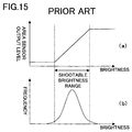
- a conventional area sensor having photosensitive devices such as photodiodes outputs a signal that is linearly proportional to the brightness of the light incident on the photosensitive devices as shown at (a) in Fig. 15.
- a subject having brightness distribution as shown at (b) in Fig. 15 is shot with such a linear-conversion-based area sensor (hereafter referred to as a "linear sensor")
- no brightness data is obtained outside the roughly two-digit brightness range (dynamic range) within which the linear sensor can effectively perform image sensing (this brightness range will hereinafter be referred to as the "shootable brightness range").
- the displayed image suffers from flat blackness in low-brightness portions thereof and saturation in high-brightness portions thereof outside the shootable brightness range. It is possible to avoid flat blackness by shifting the shootable brightness range leftward or avoid saturation by shifting it rightward. However, this requires varying the aperture value or shutter speed of a camera, or the integral time for which to allow light in, and thus spoils ease of use.
- a LOG sensor an area sensor (hereinafter referred to as a "LOG sensor") provided with a light-sensing means that outputs a photocurrent in proportion to the amount of incident light, a MOS transistor to which the photocurrent is fed, and a bias means for biasing the MOS transistor in such a way that a subthreshold current flows therethrough, so that the photocurrent is converted logarithmically.
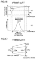
- This LOG sensor outputs a signal whose level is natural-logarithmically proportional to the amount of incident light as shown at (a) in Fig. 16, and thus offers a wide, specifically five- to six-digit, dynamic range. This permits, even in cases in which the brightness distribution tends to shift, the brightness distribution of a given subject to lie most probably within the shootable brightness range as shown at (b) in Fig. 16.
- a typical subject has a two- to three-digit brightness range, and therefore, if it is shot with a LOG sensor that offers a five- to six-digit dynamic range, the shootable brightness range is too wide relative to the actual brightness distribution of the subject, and thus a region where no brightness data is available is left in a low-brightness or high-brightness portion of the shootable brightness range.
- the range DRb of the output that corresponds to the brightness distribution of the subject is considerably narrow.
- the output device receives a signal whose level varies only within a range DRd which is merely a portion of the range covered by the eight-bit digital signal.
- An object of the present invention is to provide an image-sensing apparatus that performs signal processing in such a way as to adapt the dynamic range of an image shot with a LOG sensor to the dynamic range of an output device.
- an image-sensing apparatus is provided with: a photoelectric conversion device, having a plurality of photosensitive devices that produce electric signals in accordance with the brightness of light incident thereon, for converting logarithmically the electric signals produced by the individual photosensitive devices; a determiner for determining the brightness range of a subject; and a converter for performing level conversion on the electric signals output from the photoelectric conversion device in such a way that the brightness range of the subject as determined by the determiner is adapted to the dynamic range of an output device used to reproduce an image.
- the output level of the sensor is converted in such a way that the brightness range of the subject is adapted to the dynamic range of the output device, and thus it is possible to feed the output device with a signal that conforms to the dynamic range of the output device.
- Fig. 1 is a block diagram showing the configuration of the image-sensing apparatus of this embodiment.
- This image-sensing apparatus is of a type that employs a logarithm-conversion-based area sensor (LOG sensor) and that permits shooting of a subject in motion.
- LOG sensor logarithm-conversion-based area sensor
- the image-sensing apparatus shown in Fig. 1 has an area sensor 1 that has pixels, realized with photosensitive devices, arranged in a matrix and that produces an electric signal (hereafter referred to as the "image data") by logarithmically converting the brightness of light incident thereon, a black-level detector 2 that detects, among a plurality of pixels constituting the image data, the signal level of that pixel which shows the lowest signal level (hereafter referred to as the "black level”), a white-level detector 3 that detects, among the plurality of pixels constituting the image data, the signal level of that pixel which shows the highest signal level (hereafter referred to as the "white level”), a calculation formula determiner 4 that determines, using the black and white levels detected by the black-level and white-level detectors 2 and 3, the calculation formula to be used by a dynamic range converter 5, a dynamic range converter 5 that performs calculation on the image data output from the area sensor 1 using the calculation formula determined by the calculation formula determiner 4, and an output device 6, such
- the shootable brightness range of the area sensor 1 and the brightness distribution of the subject have a relationship as shown at (a) in Fig. 2, where the brightness that corresponds to the black level detected by the black-level detector 2 is marked PA and the brightness that corresponds to the white level detected by the white-level detector 3 is marked PB.
- These brightness values PA and PB correspond to BL and WL, respectively, at (b) in Fig. 2.
- FIG. 2 At (b) in Fig. 2 is shown the relationship between the level of the output signal from the area sensor 1 (taken along the horizontal axis) and the level of the signal fed to the output device 6 (taken along the vertical axis).
- the characteristic (A) indicated by a dotted line is the characteristic of the output device obtained when the output signal from the area sensor 1 is used intact.
- a dynamic range DR1 is obtained, with the maximum and minimum values at Ma and Mi.
- This dynamic range DR1 covers input levels ranging from Wa to Wb, which corresponds to the entire shootable brightness range of the area sensor 1.
- the output signal from the area sensor 1 lies within the range BL-WL, which lies inside the entire range covered by the characteristic (A). This makes the range DR2 of the signal fed to the output device 6 unnecessarily narrow, and makes the output image low-contrast as described earlier.
- This calculation formula (1) is given from the calculation formula determiner 4 to the dynamic range converter 5, so that the dynamic range converter 5 substitutes the signal level of the image data fed from the area sensor 1 as x in the calculation formula (1) and thereby converts the signal level into y.
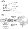
- This conversion permits the image data, having a range BL-WL, output from the area sensor 1 to be converted into image data having signal levels adapted to the dynamic range DR1 of the output device 6 as shown in Fig. 3. That is, whereas the signal fed to the output device 6 has a range DR2 when the output signal from the area sensor 1 is used intact as described previously, in this embodiment this range is expanded to a range DR1, which conforms to the dynamic range of the output device 6. This helps prevent a region from being left within the shootable brightness range where no part of the brightness range of the subject lies, and thereby permits the output device 6 to output a satisfactory high-contrast image.
- the dynamic range converter 5 may be provided with a delay circuit so that, when it is given a calculation formula like the calculation formula (1) from the calculation formula determiner 4, it can perform calculation on the image data of the same frame that was used to determine the calculation formula.
- the dynamic range converter 5 may perform calculation on image data using the calculation formula determined on the basis of the image data of the previous frame.
- the calculation formula may be determined every predetermined number of frames so that the dynamic range converter 5 continues performing calculation on image data using the calculation formula determined previously until a new one is determined next time.
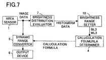
- Fig. 4 is a block diagram showing the configuration of the image-sensing apparatus of this embodiment. It is to be noted that, in the following descriptions of this embodiment, such blocks as serve the same purposes as in Fig. 2 are identified with the same reference numerals, and their detailed descriptions will be omitted.
- the image-sensing apparatus shown in Fig. 4 has an area sensor 1, a black-level detector 2, a white-level detector 3, a calculation formula determiner 4, a dynamic range converter 5, an output device 6, and a brightness distribution evaluator 7 for evaluating the brightness distribution (histogram) of the image data output from the area sensor 1.
- this image-sensing apparatus configured as described above, when image data corresponding to one frame is fed from the area sensor 1 to the brightness distribution evaluator 7, the signal levels of the individual pixels constituting this image data corresponding to one frame are measured so that the frequencies of different signal levels within the image data are counted. That is, how many of the pixels of the area sensor 1 are illuminated with light of a particular brightness value is counted for each of possible brightness values. In this way, by counting the frequencies of different brightness values in the image data of a subject, the brightness distribution evaluator 7 evaluates the brightness distribution of the subject.
- the brightness distribution evaluator 7 calculates the summation of the signal levels of all of the pixels constituting the image data corresponding to one frame in order to calculate the integral of the brightness distribution in the interval between brightness PA and brightness PB shown at (a) in Fig. 5 (this value will hereafter be referred to as "the value of the area of the entire brightness distribution").
- this value is equal to Z
- the brightness values PA and PB are defined in the same manner as in the first embodiment.
- the image data has levels BL and WL, respectively, as shown at (b) in Fig. 5.
- this value Z representing the value of the area of the entire brightness distribution is calculated, it is fed to the black-level and white-level detectors 2 and 3. Moreover, at this time, the brightness distribution evaluator 7 feeds the image data of the sensed frame, on the one hand starting with that of the pixels showing the lowest signal level upward, to the black-level detector 2 and, on the other hand starting with that of the pixels showing the highest signal level downward, to the white-level detector 3.
- the black-level and white-level detectors 2 and 3 On receiving the image data from the brightness distribution evaluator 7, the black-level and white-level detectors 2 and 3 each add together the signal levels of the image data one after another in the order in which they receive them. When the value of the added-up signal levels reach ⁇ percent of the value Z, i.e. ⁇ ⁇ Z / 100 , the black-level and white-level detectors 2 and 3 detect the signal level of the image data at that moment.
- This value ⁇ may be specified from the outside, or may be stored beforehand in memory (not shown) or the like. It is also possible to specify different values of ⁇ for the black-level and white-level detectors 2 and 3.
- the levels of the image data thus detected in the black-level and white-level detectors 2 and 3 are used as the black level and the white level, respectively.
- the black and white levels detected here are marked BL1 and WL1 at (b) in Fig. 5.
- these black and white levels BL1 and WL1 correspond to the brightness marked PA1 and PB1, respectively.
- the value ⁇ ⁇ Z / 100 corresponds to one of the portions thereof covering brightness from PA to PA1 and from PB to PB1, of which each has an area that is equal to ⁇ percent of the value of the area of the entire brightness distribution.
- the calculation formula determiner 4 determines a calculation formula that is the same as the calculation formula (1) used in the first embodiment except that the black and white levels BL1 and WL1 are used instead of the black and white levels BL and WL. Subsequently, as in the first embodiment, using the thus determined calculation formula, the dynamic range converter 5 performs calculation on the image data output from the area sensor 1.
- Fig. 6 is a block diagram showing the configuration of the image-sensing apparatus of this embodiment. It is to be noted that, in the following descriptions of this embodiment, such blocks as serve the same purposes as in Fig. 1 are identified with the same reference numerals, and their detailed descriptions will be omitted.
- the image-sensing apparatus shown in Fig. 6 has an area sensor 1, a calculation formula determiner 4, a dynamic range converter 5, an output device 6, a black-level feeder 8 for allowing entry of a black-level value from the outside, and a white-level feeder 9 for allowing entry of a white-level value from the outside.
- a black level BL2 and a white level WL2 are entered into the black-level and white-level feeders 8 and 9 from the outside by the user in accordance with the brightness range that the user desires.
- the black and white levels BL2 and WL2 entered into the black-level and white-level feeders 8 and 9 are then fed to the calculation formula determiner 4.
- the calculation formula determiner 4 determines a calculation formula that is the same as the calculation formula (1) used in the first embodiment except that the black and white levels BL2 and WL2 are used instead of the black and white levels BL and WL.
- the dynamic range converter 5 performs calculation on the image data output from the area sensor 1.
- This image-sensing apparatus permits the user to enter a black level and a white level.
- the user can set the brightness range as desired while observing an image displayed on the output device 6 such as a display, and can thus obtain an image to his or her liking.
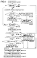
- Fig. 7 is a block diagram showing the configuration of the image-sensing apparatus of this embodiment. It is to be noted that, in the following descriptions of this embodiment, such blocks as serve the same purposes as in Fig. 4 are identified with the same reference numerals, and their detailed descriptions will be omitted.
- the image-sensing apparatus shown in Fig. 7 has an area sensor 1, a calculation formula determiner 4, a dynamic range converter 5, an output device 6, a brightness distribution evaluator 7, and a brightness range setter 10 that determines the brightness range of a subject in accordance with the shape of the brightness distribution evaluated by the brightness distribution evaluator 7.
- the brightness range that is fed to the output device is determined not solely on the basis of the maximum and minimum values of the brightness distribution of the subject, but also in consideration of the shape of the brightness distribution.
- Fig. 8 is a flow chart showing the flow of operations performed by the brightness range setter 10 to determine a brightness range.
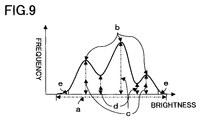
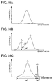
- Fig. 9 shows an example of brightness distribution, with brightness taken along the horizontal axis and the frequencies of different brightness values taken along the vertical axis.
- a point that corresponds to a maximum value is referred to as a "ridge” and a point that corresponds to a minimum value is referred to as a "trough”;
- the frequency observed at a ridge is referred to as “the height of the ridge” and the frequency observed at a trough is referred to as “the height of the trough”;
- the portions of the brightness distribution near both ends thereof, where the frequencies observed are largely low, are called “hem portions”.
- the brightness distribution evaluator 7 evaluates the brightness distribution of the subject. Subsequently, when the brightness distribution evaluated by the brightness distribution evaluator 7 is fed to the brightness range setter 10, first, the number of ridges is counted (STEP 1). If the number of ridges thus counted is one as shown in Fig. 10A (Yes), the operation flow proceeds to STEP 15; if the number of ridges is more than one as shown in Fig. 10B (No), the operation flow proceeds to STEP 3 (STEP 2). When the operation flow proceeds from STEP 2 to STEP 3, the height of the trough is measured.
- the operation flow proceeds to STEP 5; if that ratio is less than the threshold value Ta (No), the operation flow proceeds to STEP 6 (STEP 4). That is, in the case shown in Fig. 10B, in STEP 4, whether the ratio (d1) / (c1) of the height d1 of the trough B to the height of the lower one of the ridges A and C adjacent thereto is greater than Ta or not is checked.
- the two ridges adjacent to the trough is regarded as a single ridge as a whole. That is, in Fig. 10B, if the trough B is so high that the ratio of its height to the height of the lower ridge A is greater than the threshold value Ta, the lower ridge A is regarded no longer as an independent ridge but as part of the higher ridge C.
- the two ridges adjacent to the trough are regarded as separate and thus independent ridges. That is, in Fig. 10B, if the trough B is so low that the ratio of its height to the height of the lower ridge A is lower than the threshold value Ta, the ridges A and C are regarded as independent ridges.
- the two ridges adjacent to the trough are found to be separate from each other, then, if any of those two ridges has a brightness range narrower than a threshold value Tb, it is no longer regarded as a ridge and is excluded from the brightness distribution (STEP 7).
- the brightness range of a ridge is defined as the range between the brightness values at the two troughs adjacent thereto, or alternatively, in the case of a ridge located at one end of the brightness distribution, as the range between that end and the brightness value at the trough adjacent to the ridge on the opposite side thereof.
- the brightness range e1 of the ridge A is wider than the threshold value Tb, and the brightness range e2 of the ridge C is narrower than the threshold value Tb, the ridge C is no longer regarded as a ridge and is excluded from the brightness distribution.
- STEP 9 the number of ridges is counted once again. If the number of ridges counted here is one (Yes), the operation flow proceeds to STEP 15; if the number of ridges is more than one (No), the operation flow proceeds to STEP 11 (STEP 10). In STEP 11, whether the number of ridges is two or not is checked. If the number of ridges is two (Yes), the operation flow proceeds to STEP 12; if the number of ridges is three or more (No), the operation flow proceeds to STEP 14. In STEP 12, whether the area ratio calculated by dividing the area of the ridge having the larger area by that of the ridge having the smaller area is greater than a threshold value Tc or not is checked. If this area ratio is greater than the threshold value Tc (Yes), the operation flow proceeds to STEP 13, where the ridge having the smaller area is excluded from the brightness distribution; if the area ratio is smaller than the threshold value Tc (No), the operation flow proceeds to STEP 15.
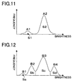
- the ridge having the smaller area is excluded from the brightness distribution, and the remaining portion is determined as the effective region. That is, as shown in Fig. 11, if, in STEP 9, two ridges A1 and A2 are recognized, their respective areas S1 and S2 are calculated, and then, since S1 ⁇ S2 here, the area ratio (S2) / (S1) is compared with the threshold value Tc (STEP 12). In this case, if the area ratio (S2) / (S1) is greater than the threshold value Tc, the ridge A1 having the smaller area is excluded from the brightness distribution, and thus the brightness distribution is regarded as being formed by the ridge A2.
- the area of a ridge is defined as the integral with respect to brightness of the frequencies of different brightness values between the troughs adjacent thereto, or alternatively, in the case of a ridge located at one end of the brightness distribution, as the integral with respect to brightness of the frequencies of different brightness values between that end and the trough adjacent to the ridge on the opposite side thereof.
- the one having the largest area is selected as the reference, and, in order of decreasing distance to this reference ridge, the area ratio calculated by dividing the area of each of the other ridges by the area of the reference ridge having the largest area is compared, one after another, with a threshold value Td.
- a threshold value Td any ridge of which the area ratio is smaller than the threshold value Td is no longer regarded as a ridge, and is excluded from the brightness distribution.
- the ridge B1 is checked, and its area ratio is found to be smaller than the threshold value Td.
- the ridge B1 is no longer regarded as a ridge and is thus excluded from the brightness distribution.
- the ridge B4 is checked, and its area ratio is found to be greater than the threshold value Td.
- the ridge B2 is checked, and its area ratio is found to be greater than the threshold value Td.
- the checking of the ridges that are located on the lower-brightness side of the ridge B3 is ended.
- the operation flow proceeds to STEP 15.
- the area of the ridges excluded from the brightness distribution is subtracted from the area of the entire brightness distribution, and the area that remains thereafter is determined as the effective area. That is, if only one ridge is recognized in STEP 2 or STEP 10, or if the area ratios of two ridges are smaller than the threshold value Tc in STEP 12, then the entire brightness distribution is determined as the effective area; on the other hand, when the operation flow proceeds from STEP 13 or STEP 14 to STEP 15, the area that remains after subtracting the area of the ridges excluded from the brightness distribution in STEP 13 or STEP 14 from the area of the entire brightness distribution is determined as the effective area.
- the effective area is the area of the effective region mentioned above.
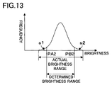
- the hem portions are determined. That is, as shown in Fig. 13, the brightness PA2 at which the value obtained by integrating the frequencies of different brightness values with respect to brightness from the lowest brightness upward within the portion of the brightness distribution that forms the effective area becomes equal to ⁇ percent of the effective area is calculated, and also the brightness PB2 at which the value obtained by integrating the frequencies of different brightness values with respect to brightness from the highest brightness downward within the portion of the brightness distribution that forms the effective area becomes equal to ⁇ percent of the effective area is calculated. Then, the portion s1 corresponding to brightness lower than the brightness PA2 and the portion s2 corresponding to brightness higher than the brightness PB2 are determined as the hem portions.
- the black level BL3 corresponding to the brightness PA2 and the white level WL3 corresponding to the brightness PB2 are fed to the calculation formula determiner 4 to make it determine a calculation formula to be used to determine a dynamic range.
- the dynamic range converter 5 performs calculation on the image data output from the area sensor 1.
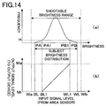
- Fig. 14 is a graph showing the relationship between the brightness distribution of a subject and the brightness range obtained by the image-sensing apparatus of this embodiment.
- the image-sensing apparatus of this embodiment has the same internal configuration as that of the second embodiment shown in Fig. 4.
- the area sensor 1, the calculation formula determiner 4, the dynamic range converter 5, the output device 6, and the brightness distribution evaluator 7 operate in the same manner as in the image-sensing apparatus of the second embodiment, and therefore no detailed descriptions will be given below as to their operation. Now, the operation of the black-level and white-level detectors 2 and 3 will be described.
- the black-level detector 2 finds the brightness PA1 at which the frequencies of different brightness values first reach a predetermined frequency H when checked from the lowest brightness PA of the brightness distribution upward, and detects the signal level at that brightness PA1 as the black level BL1.
- the white-level detector 3 finds the brightness PB1 at which the frequencies of different brightness values first reach the predetermined frequency H when checked from the highest brightness PB of the brightness distribution downward, and detects the signal level at that brightness PB1 as the white level WL1.
- the black and white levels BL1 and WL1 thus detected by the black-level and white-level detectors 2 and 3, respectively, are then fed to the calculation formula determiner 4 to make the calculation formula determiner 4 determine a calculation formula to be used to determine a dynamic range. Subsequently, using the thus determined calculation formula, the dynamic range converter 5 performs calculation on the image data output from the area sensor 1.
- the same value H is set as the predetermined frequency in both the black-level and white-level detectors 2 and 3; however, it is also possible to set different values of H for the black-level and white-level detectors 2 and 3.
- the hem portions in which the frequencies of different brightness values do not reach a predetermined value are removed from the brightness distribution evaluated.
- the above-described flow of operations performed in this embodiment may be performed on the effective region determined in the fourth embodiment in order to determine the brightness range of a subject and then find the white and black levels WL3 and BL3.
- the output device does not necessarily have to be a display as specifically named above as an example, but may be a storage device or the like that permits storage of image data on a magnetic disk.
- the present invention is applicable also to an image-sensing apparatus such as a digital camera for shooting a subject at rest.
- the signal fed from the photoelectric conversion device to an output device is subjected to level conversion in accordance with the brightness range of a subject so that the dynamic range of this signal is adapted to the dynamic range of the output device.
Landscapes
- Engineering & Computer Science (AREA)
- Multimedia (AREA)
- Signal Processing (AREA)
- Physics & Mathematics (AREA)
- Nonlinear Science (AREA)
- Exposure Control For Cameras (AREA)
- Image Input (AREA)
- Transforming Light Signals Into Electric Signals (AREA)
- Facsimile Image Signal Circuits (AREA)
- Studio Devices (AREA)
- Image Analysis (AREA)
- Solid State Image Pick-Up Elements (AREA)
Applications Claiming Priority (4)
| Application Number | Priority Date | Filing Date | Title |
|---|---|---|---|
| JP12838499 | 1999-05-10 | ||
| JP12838499 | 1999-05-10 | ||
| JP2000090683A JP4292679B2 (ja) | 1999-05-10 | 2000-03-27 | 固体撮像装置 |
| JP2000090683 | 2000-03-27 |
Publications (2)
| Publication Number | Publication Date |
|---|---|
| EP1052848A1 true EP1052848A1 (de) | 2000-11-15 |
| EP1052848B1 EP1052848B1 (de) | 2012-03-21 |
Family
ID=26464071
Family Applications (1)
| Application Number | Title | Priority Date | Filing Date |
|---|---|---|---|
| EP00109172A Expired - Lifetime EP1052848B1 (de) | 1999-05-10 | 2000-05-08 | Bildaufnahmegerät |
Country Status (3)
| Country | Link |
|---|---|
| US (1) | US7230644B2 (de) |
| EP (1) | EP1052848B1 (de) |
| JP (1) | JP4292679B2 (de) |
Cited By (8)
| Publication number | Priority date | Publication date | Assignee | Title |
|---|---|---|---|---|
| WO2002037419A1 (en) * | 2000-10-30 | 2002-05-10 | Mark Peters | Apparatus and method for the construction of spatial representations |
| EP1217830A1 (de) * | 2000-12-22 | 2002-06-26 | Kappa opto-electronics GmbH | Verfahren zur Signalverbesserung in einer mit einer digitalen Farbvideokamera aufgenommenen Bilderfolge |
| EP1705901A2 (de) | 2005-03-22 | 2006-09-27 | Omron Corporation | Bildverarbeitungsvorrichtung und Verfahren, Aufzeichnungsmedium und Programm |
| EP1868368A4 (de) * | 2005-03-15 | 2009-06-24 | Omron Tateisi Electronics Co | Bildprozessor, bildverarbeitungsverfahren, programm und aufzeichnungsmedium |
| CN101169921B (zh) * | 2006-10-26 | 2011-02-02 | 瑞萨电子株式会社 | 显示亮度控制电路 |
| EP2339830A3 (de) * | 2009-11-12 | 2011-12-28 | Semiconductor Energy Laboratory Co., Ltd. | Anzeigeeinrichtung, Halbleiterelement und Treiberverfahren dafür |
| WO2012050728A1 (en) * | 2010-09-30 | 2012-04-19 | Apple Inc. | High dynamic range transition |
| DE112006003593B4 (de) * | 2005-12-27 | 2012-06-14 | Kyocera Corp. | Bildsignalverarbeitungsverfahren und Bildsignalverarbeitungsvorrichtung |
Families Citing this family (16)
| Publication number | Priority date | Publication date | Assignee | Title |
|---|---|---|---|---|
| JP2002271698A (ja) * | 2001-03-09 | 2002-09-20 | Honda Motor Co Ltd | 光センサ回路 |
| JP3780178B2 (ja) * | 2001-05-09 | 2006-05-31 | ファナック株式会社 | 視覚センサ |
| JP4759850B2 (ja) * | 2001-05-29 | 2011-08-31 | コニカミノルタホールディングス株式会社 | 固体撮像装置 |
| JP3956311B2 (ja) * | 2004-02-19 | 2007-08-08 | オムロン株式会社 | 画像データ変換装置及びカメラ装置 |
| JP4372747B2 (ja) | 2005-01-25 | 2009-11-25 | シャープ株式会社 | 輝度レベル変換装置、輝度レベル変換方法、固体撮像装置、輝度レベル変換プログラム、および記録媒体 |
| JP4325627B2 (ja) | 2006-02-21 | 2009-09-02 | ソニー株式会社 | 画像表示方法および画像表示装置並びに撮像装置 |
| KR100696165B1 (ko) * | 2006-08-28 | 2007-03-20 | 엠텍비젼 주식회사 | 이미지 밝기 보정 장치 및 방법, 이를 수행하는 프로그램이기록된 기록 매체 |
| KR101487548B1 (ko) * | 2007-05-18 | 2015-01-29 | 소니 주식회사 | 표시 장치, 표시 장치의 제어 방법 및 컴퓨터 프로그램이 기록된 기록 매체 |
| JP2009058377A (ja) * | 2007-08-31 | 2009-03-19 | Hitachi Kokusai Electric Inc | 検査装置 |
| US8013911B2 (en) * | 2009-03-30 | 2011-09-06 | Texas Instruments Incorporated | Method for mixing high-gain and low-gain signal for wide dynamic range image sensor |
| US8643769B2 (en) * | 2010-10-12 | 2014-02-04 | Texas Instruments Incorporated | Method for capturing wide dynamic range image in a 16 bit floating point format |
| JP6486055B2 (ja) * | 2014-10-09 | 2019-03-20 | キヤノン株式会社 | 撮像装置およびその制御方法、並びにプログラム |
| JP6525543B2 (ja) * | 2014-10-21 | 2019-06-05 | キヤノン株式会社 | 画像処装置および画像処理方法、並びにプログラム |
| TWI685837B (zh) * | 2014-10-23 | 2020-02-21 | 日商新力股份有限公司 | 資訊處理裝置、資訊處理方法、及程式產品、以及記錄媒體 |
| JP6552325B2 (ja) * | 2015-08-07 | 2019-07-31 | キヤノン株式会社 | 撮像装置、撮像装置の制御方法、及びプログラム |
| US10694112B2 (en) * | 2018-01-03 | 2020-06-23 | Getac Technology Corporation | Vehicular image pickup device and image capturing method |
Citations (3)
| Publication number | Priority date | Publication date | Assignee | Title |
|---|---|---|---|---|
| US4182573A (en) | 1976-09-13 | 1980-01-08 | Minolta Camera Kabushiki Kaisha | Exposure meter |
| US4926247A (en) | 1986-10-15 | 1990-05-15 | Olympus Optical Co., Ltd. | Color imaging apparatus including a means for electronically non-linearly expanding and compressing dynamic range of an image signal |
| DE19619734A1 (de) * | 1995-05-16 | 1996-11-21 | Asahi Optical Co Ltd | Elektronisches Endoskopsystem |
Family Cites Families (16)
| Publication number | Priority date | Publication date | Assignee | Title |
|---|---|---|---|---|
| US5008698A (en) | 1987-09-28 | 1991-04-16 | Kyocera Corporation | Control apparatus for image sensor |
| US4811090A (en) | 1988-01-04 | 1989-03-07 | Hypervision | Image emission microscope with improved image processing capability |
| US5182658A (en) | 1988-07-27 | 1993-01-26 | Canon Kabushiki Kaisha | Image pickup apparatus for controlling accumulation time in photoelectric elements |
| US5241575A (en) | 1989-12-21 | 1993-08-31 | Minolta Camera Kabushiki Kaisha | Solid-state image sensing device providing a logarithmically proportional output signal |
| US5138458A (en) | 1989-12-22 | 1992-08-11 | Olympus Optical Co., Ltd. | Electronic camera apparatus capable of providing wide dynamic range image signal |
| EP0496573B1 (de) | 1991-01-24 | 1995-12-20 | Matsushita Electric Industrial Co., Ltd. | Schaltung zur Beseitigung von Bildelementdefekten für Festkörper-Bildaufnehmer |
| US5526092A (en) | 1992-09-11 | 1996-06-11 | Nikon Corporation | Photometric control device for camera |
| US5617484A (en) | 1992-09-25 | 1997-04-01 | Olympus Optical Co., Ltd. | Image binarizing apparatus |
| JPH06288821A (ja) | 1993-03-30 | 1994-10-18 | Nikon Corp | カメラの測光装置 |
| US6204881B1 (en) * | 1993-10-10 | 2001-03-20 | Canon Kabushiki Kaisha | Image data processing apparatus which can combine a plurality of images at different exposures into an image with a wider dynamic range |
| JP3669448B2 (ja) * | 1995-10-31 | 2005-07-06 | 富士写真フイルム株式会社 | 画像再生方法および装置 |
| JP3747497B2 (ja) | 1995-12-13 | 2006-02-22 | 株式会社ニコン | 測光装置 |
| JP3277984B2 (ja) * | 1997-03-31 | 2002-04-22 | 日本電気株式会社 | 映像信号処理装置 |
| US6181321B1 (en) * | 1997-04-23 | 2001-01-30 | Canon Kabushiki Kaisha | Combined color cast removal and contrast enhancement for digital color images |
| US6101294A (en) | 1997-06-02 | 2000-08-08 | Sarnoff Corporation | Extended dynamic imaging system and method |
| US6515702B1 (en) | 1997-07-14 | 2003-02-04 | California Institute Of Technology | Active pixel image sensor with a winner-take-all mode of operation |
-
2000
- 2000-03-27 JP JP2000090683A patent/JP4292679B2/ja not_active Expired - Fee Related
- 2000-05-08 EP EP00109172A patent/EP1052848B1/de not_active Expired - Lifetime
-
2005
- 2005-01-04 US US11/028,975 patent/US7230644B2/en not_active Expired - Fee Related
Patent Citations (3)
| Publication number | Priority date | Publication date | Assignee | Title |
|---|---|---|---|---|
| US4182573A (en) | 1976-09-13 | 1980-01-08 | Minolta Camera Kabushiki Kaisha | Exposure meter |
| US4926247A (en) | 1986-10-15 | 1990-05-15 | Olympus Optical Co., Ltd. | Color imaging apparatus including a means for electronically non-linearly expanding and compressing dynamic range of an image signal |
| DE19619734A1 (de) * | 1995-05-16 | 1996-11-21 | Asahi Optical Co Ltd | Elektronisches Endoskopsystem |
Cited By (14)
| Publication number | Priority date | Publication date | Assignee | Title |
|---|---|---|---|---|
| US7483571B2 (en) | 2000-10-30 | 2009-01-27 | Peters Mark W | Apparatus and method for the construction of spatial representations |
| WO2002037419A1 (en) * | 2000-10-30 | 2002-05-10 | Mark Peters | Apparatus and method for the construction of spatial representations |
| EP1217830A1 (de) * | 2000-12-22 | 2002-06-26 | Kappa opto-electronics GmbH | Verfahren zur Signalverbesserung in einer mit einer digitalen Farbvideokamera aufgenommenen Bilderfolge |
| US6963364B2 (en) | 2000-12-22 | 2005-11-08 | Kappa Opto-Electronics Gmbh | Method of improving a signal in a sequence of images acquired with a digital color video camera |
| EP1868368A4 (de) * | 2005-03-15 | 2009-06-24 | Omron Tateisi Electronics Co | Bildprozessor, bildverarbeitungsverfahren, programm und aufzeichnungsmedium |
| EP1705901A2 (de) | 2005-03-22 | 2006-09-27 | Omron Corporation | Bildverarbeitungsvorrichtung und Verfahren, Aufzeichnungsmedium und Programm |
| EP1705901A3 (de) * | 2005-03-22 | 2007-11-07 | Omron Corporation | Bildverarbeitungsvorrichtung und Verfahren, Aufzeichnungsmedium und Programm |
| DE112006003593B4 (de) * | 2005-12-27 | 2012-06-14 | Kyocera Corp. | Bildsignalverarbeitungsverfahren und Bildsignalverarbeitungsvorrichtung |
| CN101169921B (zh) * | 2006-10-26 | 2011-02-02 | 瑞萨电子株式会社 | 显示亮度控制电路 |
| EP2339830A3 (de) * | 2009-11-12 | 2011-12-28 | Semiconductor Energy Laboratory Co., Ltd. | Anzeigeeinrichtung, Halbleiterelement und Treiberverfahren dafür |
| US8519981B2 (en) | 2009-11-12 | 2013-08-27 | Semiconductor Energy Laboratory Co., Ltd. | Semiconductor device |
| WO2012050728A1 (en) * | 2010-09-30 | 2012-04-19 | Apple Inc. | High dynamic range transition |
| CN103222259A (zh) * | 2010-09-30 | 2013-07-24 | 苹果公司 | 高动态范围的转换 |
| US9584733B2 (en) | 2010-09-30 | 2017-02-28 | Apple Inc. | High dynamic range transition |
Also Published As
| Publication number | Publication date |
|---|---|
| JP4292679B2 (ja) | 2009-07-08 |
| US7230644B2 (en) | 2007-06-12 |
| JP2001028714A (ja) | 2001-01-30 |
| US20050218295A1 (en) | 2005-10-06 |
| EP1052848B1 (de) | 2012-03-21 |
Similar Documents
| Publication | Publication Date | Title |
|---|---|---|
| EP1052848A1 (de) | Bildaufnahmegerät | |
| US8890972B2 (en) | Image capturing apparatus and image processing method | |
| KR101419947B1 (ko) | 촬상 장치, 측광 방법, 휘도 산출 방법, 및 저장 매체 | |
| US9137450B2 (en) | Image sensing apparatus, exposure control method and recording medium | |
| US7714928B2 (en) | Image sensing apparatus and an image sensing method comprising a logarithmic characteristic area and a linear characteristic area | |
| US7508422B2 (en) | Image sensing apparatus comprising a logarithmic characteristic area and a linear characteristic area | |
| US20110149111A1 (en) | Creating an image using still and preview | |
| US7692693B2 (en) | Imaging apparatus | |
| CN102169276A (zh) | 摄像装置和自动焦点调节方法 | |
| US7483064B2 (en) | Imaging apparatus | |
| US7978912B2 (en) | Image sensing apparatus and image sensing method | |
| CN103888667B (zh) | 摄像设备及其控制方法 | |
| US8379126B2 (en) | Image-sensing apparatus | |
| US20030202108A1 (en) | Image pick-up apparatus | |
| US20040012711A1 (en) | Image pickup apparatus and photometer | |
| JP3394019B2 (ja) | 画像入力装置の露光制御回路 | |
| US8614767B2 (en) | Preview image display compensation based on environmental lighting conditions | |
| JPH1013749A (ja) | 光電変換器の暗電流補正装置 | |
| JP3274692B2 (ja) | 画像入力装置の露光制御回路 | |
| JP4047000B2 (ja) | 撮像装置及び撮像方法 | |
| JP4735051B2 (ja) | 撮像装置 | |
| US7898591B2 (en) | Method and apparatus for imaging using sensitivity coefficients | |
| JP3792555B2 (ja) | 明度調整方法および撮像装置 | |
| JP2002112108A (ja) | 画像処理装置 | |
| JP2006332936A (ja) | 撮像装置 |
Legal Events
| Date | Code | Title | Description |
|---|---|---|---|
| PUAI | Public reference made under article 153(3) epc to a published international application that has entered the european phase |
Free format text: ORIGINAL CODE: 0009012 |
|
| 17P | Request for examination filed |
Effective date: 20000508 |
|
| AK | Designated contracting states |
Kind code of ref document: A1 Designated state(s): DE FR GB |
|
| AX | Request for extension of the european patent |
Free format text: AL;LT;LV;MK;RO;SI |
|
| AKX | Designation fees paid |
Free format text: DE FR GB |
|
| 17Q | First examination report despatched |
Effective date: 20070413 |
|
| GRAP | Despatch of communication of intention to grant a patent |
Free format text: ORIGINAL CODE: EPIDOSNIGR1 |
|
| GRAS | Grant fee paid |
Free format text: ORIGINAL CODE: EPIDOSNIGR3 |
|
| GRAA | (expected) grant |
Free format text: ORIGINAL CODE: 0009210 |
|
| AK | Designated contracting states |
Kind code of ref document: B1 Designated state(s): DE FR GB |
|
| REG | Reference to a national code |
Ref country code: GB Ref legal event code: FG4D |
|
| REG | Reference to a national code |
Ref country code: DE Ref legal event code: R096 Ref document number: 60047012 Country of ref document: DE Effective date: 20120516 |
|
| PLBE | No opposition filed within time limit |
Free format text: ORIGINAL CODE: 0009261 |
|
| STAA | Information on the status of an ep patent application or granted ep patent |
Free format text: STATUS: NO OPPOSITION FILED WITHIN TIME LIMIT |
|
| 26N | No opposition filed |
Effective date: 20130102 |
|
| REG | Reference to a national code |
Ref country code: DE Ref legal event code: R097 Ref document number: 60047012 Country of ref document: DE Effective date: 20130102 |
|
| REG | Reference to a national code |
Ref country code: FR Ref legal event code: PLFP Year of fee payment: 16 |
|
| PGFP | Annual fee paid to national office [announced via postgrant information from national office to epo] |
Ref country code: DE Payment date: 20150506 Year of fee payment: 16 Ref country code: GB Payment date: 20150506 Year of fee payment: 16 |
|
| PGFP | Annual fee paid to national office [announced via postgrant information from national office to epo] |
Ref country code: FR Payment date: 20150508 Year of fee payment: 16 |
|
| REG | Reference to a national code |
Ref country code: DE Ref legal event code: R119 Ref document number: 60047012 Country of ref document: DE |
|
| GBPC | Gb: european patent ceased through non-payment of renewal fee |
Effective date: 20160508 |
|
| REG | Reference to a national code |
Ref country code: FR Ref legal event code: ST Effective date: 20170131 |
|
| PG25 | Lapsed in a contracting state [announced via postgrant information from national office to epo] |
Ref country code: DE Free format text: LAPSE BECAUSE OF NON-PAYMENT OF DUE FEES Effective date: 20161201 Ref country code: FR Free format text: LAPSE BECAUSE OF NON-PAYMENT OF DUE FEES Effective date: 20160531 |
|
| PG25 | Lapsed in a contracting state [announced via postgrant information from national office to epo] |
Ref country code: GB Free format text: LAPSE BECAUSE OF NON-PAYMENT OF DUE FEES Effective date: 20160508 |